warning JEEP COMPASS 2021 Owner handbook (in English)
[x] Cancel search | Manufacturer: JEEP, Model Year: 2021, Model line: COMPASS, Model: JEEP COMPASS 2021Pages: 328, PDF Size: 8.85 MB
Page 51 of 328
49
HOOD
Opening The Hood
Two latches must be released to open the
hood.
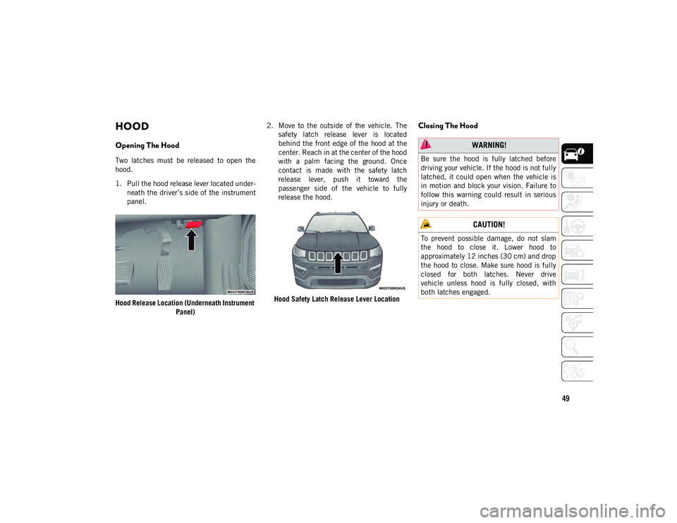
1. Pull the hood release lever located under-
neath the driver’s side of the instrument
panel.
Hood Release Location (Underneath Instrument Panel) 2. Move to the outside of the vehicle. The
safety latch release lever is located
behind the front edge of the hood at the
center. Reach in at the center of the hood
with a palm facing the ground. Once
contact is made with the safety latch
release lever, push it toward the
passenger side of the vehicle to fully
release the hood.
Hood Safety Latch Release Lever Location
Closing The Hood
WARNING!
Be sure the hood is fully latched before
driving your vehicle. If the hood is not fully
latched, it could open when the vehicle is
in motion and block your vision. Failure to
follow this warning could result in serious
injury or death.
CAUTION!
To prevent possible damage, do not slam
the hood to close it. Lower hood to
approximately 12 inches (30 cm) and drop
the hood to close. Make sure hood is fully
closed for both latches. Never drive
vehicle unless hood is fully closed, with
both latches engaged.
2020_JEEP_M6_UG_UK.book Page 49
Page 52 of 328
GETTING TO KNOW YOUR VEHICLE
50
LIFTGATE
Opening
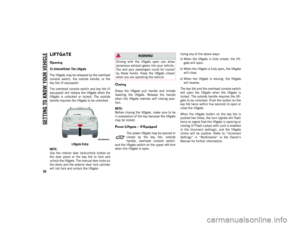
To Unlock/Enter The Liftgate
The liftgate may be released by the overhead
console switch, the outside handle, or the
key fob (if equipped).
The overhead console switch and key fob (if
equipped) will release the liftgate when the
liftgate is unlocked or locked. The outside
handle requires the liftgate to be unlocked.Liftgate Entry
NOTE:
Use the interior door lock/unlock button on
the door panel or the key fob to lock and
unlock the liftgate. The manual door locks on
the doors and the exterior door lock cylinder
will not lock and unlock the liftgate.
Closing
Grasp the liftgate pull handle and initiate
lowering the liftgate. Release the handle
when the liftgate reaches self closing posi -
tion.
NOTE:
Before closing the liftgate, make sure to be
in possession of the key because the liftgate
may be locked.
Power Liftgate — If Equipped
The power liftgate may be opened or
closed by the key fob, outside
handle, overhead console switch,
and the liftgate switch on the upper left trim
when the liftgate is open. Using any of the above ways:
When the liftgate is fully closed, the lift
-
gate will open.
When the liftgate is fully open, the liftgate
will close.
When the liftgate is moving, the liftgate
will reverse.
The key fob and the overhead console switch
will open the liftgate when the liftgate is
locked. The outside handle requires the lift -
gate to be unlocked. Push the button on the
key fob twice within five seconds to open or
close the liftgate.
When the liftgate button on the key fob is
pushed two times, the turn signals will flash
twice to signal that the liftgate is opening or
closing (if Flash Lamps with Lock is enabled
in the Uconnect settings), and the liftgate
chime will be audible. Refer to “Uconnect
Settings” in “Multimedia” in the Owner’s
Manual for further information.
WARNING!
Driving with the liftgate open can allow
poisonous exhaust gases into your vehicle.
You and your passengers could be injured
by these fumes. Keep the liftgate closed
when you are operating the vehicle.
2020_JEEP_M6_UG_UK.book Page 50
Page 53 of 328
51
(Continued)
NOTE:
Before closing the liftgate, make sure to
be in possession of the key because the
liftgate may be locked.
Use the interior door lock/unlock button
on the door panel or the key fob to lock
and unlock the liftgate. The manual door
locks on the doors and the exterior door
lock cylinder will not lock and unlock the
liftgate.
Lock The Vehicle
NOTE:
The liftgate will not power open or close if
the gear selector is in gear or the vehicle
speed is above 0 mph (0 km/h).
If anything obstructs the power liftgate
while it is closing or opening, the liftgate
will automatically reverse to the closed or
open position, provided it meets sufficient
resistance.
There are pinch sensors attached to the
side of the liftgate opening. Light pressure
anywhere along these strips will cause the
liftgate to return to the open position.
If the power liftgate encounters multiple
obstructions within the same cycle, the
system will automatically stop. If this
occurs, the liftgate must be opened or
closed manually.
The power liftgate will not operate in
temperatures below −22°F (−30°C) or
temperatures above 150°F (65°C). Be
sure to remove any buildup of snow or ice
from the liftgate before pushing any of the
power liftgate switches.
If the liftgate is left open for an extended
period of time, the liftgate may need to be
closed manually to reset power liftgate
functionality.
Gas props support the liftgate in the open
position. However, because the gas pres-
sure drops with temperature, it may be
necessary to assist the props when
opening the liftgate in cold weather.
Before driving off, check the instrument
cluster for a liftgate or door open message
or warning indicator. Failure to do this
could result in unintentionally leaving the
liftgate open while driving.
If your liftgate is power closing and you
put the vehicle in gear, the liftgate will
continue to power close. However, vehicle
movement may result in a detection of an
obstruction.
If the electronic liftgate release handle is
pushed while the power liftgate is
opening, the liftgate motor will disengage
to allow manual operation.
If the electronic liftgate release handle is
pushed while the power liftgate is closing,
the liftgate will reverse to the full open
position.
WARNING!
During power operation, personal injury or
cargo damage may occur. Ensure the
liftgate travel path is clear. Make sure the
liftgate is closed and latched before
driving away.
WARNING!
Driving with the liftgate open can allow
poisonous exhaust gases into your
vehicle. You and your passengers could
be injured by these fumes. Keep the lift -
gate closed when you are operating the
vehicle.
2020_JEEP_M6_UG_UK.book Page 51
Page 54 of 328
GETTING TO KNOW YOUR VEHICLE
52
NOTE:
Allow the power system to open the liftgate.
Manually pushing or pulling the liftgate may
activate the liftgate obstacle detection
feature and stop the power operation or
reverse its direction.
INTERNAL EQUIPMENT
Power Outlets
Your vehicle is equipped with 12 Volt (13 Amp)
power outlets that can be used to power cellular
phones, small electronics and other low
powered electrical accessories. The power
outlets are labeled with either a “key” or a“battery” symbol to indicate how the outlet is
powered. Power outlets labeled with a “key”
are powered when the ignition is in the ON or
ACC position, while the outlets labeled with a
“battery” are connected directly to the battery
and powered at all times.
NOTE:
All accessories connected to the “battery”
powered outlets should be removed or turned
off when the vehicle is not in use to protect
the battery against discharge.
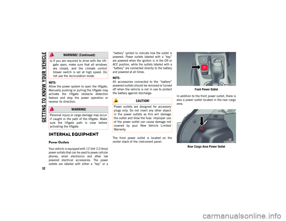
The front power outlet is located on the
center stack of the instrument panel.
Front Power Outlet
In addition to the front power outlet, there is
also a power outlet located in the rear cargo
area.
Rear Cargo Area Power Outlet
If you are required to drive with the lift -
gate open, make sure that all windows
are closed, and the climate control
blower switch is set at high speed. Do
not use the recirculation mode.
WARNING!
Personal injury or cargo damage may occur
if caught in the path of the liftgate. Make
sure the liftgate path is clear before
activating the liftgate.
WARNING! (Continued)
CAUTION!
Power outlets are designed for accessory
plugs only. Do not insert any other object
in the power outlets as this will damage
the outlet and blow the fuse. Improper use
of the power outlet can cause damage not
covered by your New Vehicle Limited
Warranty.
2020_JEEP_M6_UG_UK.book Page 52
Page 55 of 328
53
(Continued)
NOTE:
The rear cargo area power outlet can be
switched from “ignition” only to constant
“battery” powered all the time. See an
authorized dealer for details.
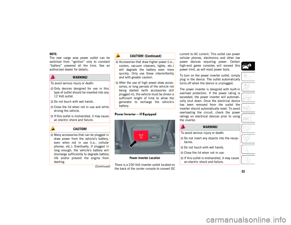
Power Inverter — If Equipped
Power Inverter Location
There is a 230 Volt inverter outlet located on
the back of the center console to convert DC current to AC current. This outlet can power
cellular phones, electronics and other low
power devices requiring power. Certain
high-end game consoles will exceed this
power limit, as will most power tools.
To turn on the power inverter outlet, simply
plug in the device. The outlet automatically
turns off when the device is unplugged.
The power inverter is designed with built-in
overload protection. If the power rating is
exceeded, the power inverter will automati
-
cally shut down. Once the electrical device
has been removed from the outlet the
inverter should automatically reset. To avoid
overloading the circuit, check the power
ratings on electrical devices prior to using
the inverter.
WARNING!
To avoid serious injury or death:
Only devices designed for use in this
type of outlet should be inserted into any
12 Volt outlet.
Do not touch with wet hands.
Close the lid when not in use and while
driving the vehicle.
If this outlet is mishandled, it may cause
an electric shock and failure.
CAUTION!
Many accessories that can be plugged in
draw power from the vehicle's battery,
even when not in use (i.e., cellular
phones, etc.). Eventually, if plugged in
long enough, the vehicle's battery will
discharge sufficiently to degrade battery
life and/or prevent the engine from
starting.
Accessories that draw higher power (i.e.,
coolers, vacuum cleaners, lights, etc.)
will degrade the battery even more
quickly. Only use these intermittently
and with greater caution.
After the use of high power draw acces-
sories, or long periods of the vehicle not
being started (with accessories still
plugged in), the vehicle must be driven a
sufficient length of time to allow the
generator to recharge the vehicle's
battery.
CAUTION! (Continued)
WARNING!
To avoid serious injury or death:
Do not insert any objects into the recep -
tacles.
Do not touch with wet hands.
Close the lid when not in use.
If this outlet is mishandled, it may cause
an electric shock and failure.
2020_JEEP_M6_UG_UK.book Page 53
Page 56 of 328
GETTING TO KNOW YOUR VEHICLE
54
(Continued)
ROOF LUGGAGE RACK — IF
EQUIPPED
The load carried on the roof, when equipped
with a luggage rack, must not exceed 150 lbs
(68 kg), and it should be uniformly distrib-
uted over the cargo area.
Crossbars should always be used whenever
cargo is placed on the roof rack. Check the
straps frequently to be sure that the load
remains securely attached.
NOTE:
Crossbars can be purchased at your autho -
rized dealer through Mopar parts.
External racks do not increase the total load
carrying capacity of the vehicle. Be sure that
the total occupant and luggage load inside
the vehicle, plus the load on the luggage
rack, do not exceed the maximum vehicle
load capacity.
WARNING!
Cargo must be securely tied down before
driving your vehicle. Improperly secured
loads can fly off the vehicle, particularly at
high speeds, resulting in personal injury or
property damage. Follow the roof rack
cautions when carrying cargo on your roof
rack.
CAUTION!
To avoid damage to the roof rack and
vehicle, do not exceed the maximum roof
rack load capacity. Always distribute
heavy loads as evenly as possible and
secure the load appropriately.
Long loads, which extend over the wind -
shield, should be secured to both the
front and rear of the vehicle.
Place a blanket or other protection
between the surface of the roof and the
load.
Travel at reduced speeds and turn
corners carefully when carrying large or
heavy loads on the roof rack. Wind
forces, due to natural causes or nearby
truck traffic, can add sudden upward
loads. It is recommended to not carry
large flat loads, such as wood panels or
surfboards, which may result in damage
to the cargo or your vehicle.
Load should always be secured to cross
bars first, with tie down loops used as
additional securing points if needed. Tie
loops are intended as supplementary tie
down points only. Do not use ratcheting
mechanisms with the tie loops. Check
the straps frequently to be sure that the
load remains securely attached.
CAUTION! (Continued)
2020_JEEP_M6_UG_UK.book Page 54
Page 57 of 328
55
GETTING TO KNOW YOUR INSTRUMENT PANEL
INSTRUMENT CLUSTER
DISPLAY
Your vehicle may be equipped with an instru-
ment cluster display, which offers useful
information to the driver. With the ignition in
the STOP/OFF mode, opening/closing of a
door will activate the display for viewing, and
display the total miles, or kilometers, in the
odometer. Your instrument cluster display is
designed to display important information
about your vehicle’s systems and features.
Using a driver interactive display located on
the instrument panel, your instrument
cluster display can show you how systems
are working and give you warnings when they
aren’t. The steering wheel mounted controls
allow you to scroll through and enter the
main menus and submenus. You can access
the specific information you want and make
selections and adjustments.
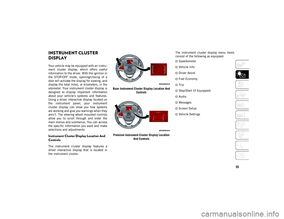
Instrument Cluster Display Location And
Controls
The instrument cluster display features a
driver interactive display that is located in
the instrument cluster. Base Instrument Cluster Display Location And
Controls
Premium Instrument Cluster Display Location And Controls The instrument cluster display menu items
consist of the following as equipped:
Speedometer
Vehicle Info
Driver Assist
Fuel Economy
Trip
Stop/Start (If Equipped)
Audio
Messages
Screen Setup
Vehicle Settings
2020_JEEP_M6_UG_UK.book Page 55
Page 60 of 328
GETTING TO KNOW YOUR INSTRUMENT PANEL
58MESSAGE
DESCRIPTION
Diesel Emissions Additive AdBlue® (UREA) Warning Messages:
Low Diesel Emissions Additive
AdBlue® (UREA) Level Warning The first low level warning will be given at around a 1,490 miles (2,400 km) range, and is determined
according to the current consumption rate. The “UREA Low Level” warning light and message will
display on the instrument panel. The UREA low level warning light will remains lit until the AdBlue®
(UREA) tank is topped up with at least 1.32 gallons (5 Liters) of UREA.
If the level is not resolved, an additional warning appear whenever a certain threshold is reached until it
will no longer be possible to start the engine.
When 125 miles (200 km) are remaining before the AdBlue® (UREA) tank is empty, a message will
appear on the instrument panel, accompanied by a buzzer sound. When the range is at 0, the display
will show a dedicated message (if equipped). In this case, the engine will not restart.
It will be possible to restart the engine again as soon as AdBlue® (UREA) is added; the minimum
amount required is 1.32 gallons (5 Liters). Fill the AdBlue® (UREA) tank as soon as possible with at
least 1.32 gallons (5 Liters) of UREA. If filling is completed with autonomy tank AdBlue® (UREA) to
zero, it could be possible to wait two minutes before starting the vehicle.
NOTE:
When the AdBlue® (UREA) tank is empty, and the vehicle is stopped, it is no longer possible to restart
the vehicle until a minimum of 1.32 gallons (5 Liters) of AdBlue® (UREA) is added to the AdBlue®
(UREA) tank.
Diesel Emissions Additive AdBlue® (UREA) Fault Warning Messages:
Engine Will Not Restart Service
AdBlue® System See Dealer This message will display if AdBlue® (UREA) system issue detected is not serviced during the allowed
period. Your engine will not restart unless your vehicle is serviced by your authorized dealer. If the level
is not resolved, an additional warning appear whenever a certain threshold is reached until it will no
longer be possible to start the engine. When 125 miles (200 km) are remaining before the AdBlue®
tank is empty, a message will appear on the instrument panel, accompanied by a buzzer sound.
2020_JEEP_M6_UG_UK.book Page 58
Page 61 of 328
59
TRIP COMPUTER
Push and release the up or down arrow
button until the Trip A or Trip B icon is high-
lighted in the instrument cluster display
(Toggle left or right to select Trip A or Trip B).
Push and release the OK button to display
the Trip information.
WARNING LIGHTS AND
MESSAGES
The warning/indicator lights will illuminate
in the instrument panel together with a dedi -
cated message and/or acoustic signal when
applicable. These indications are indicative
and precautionary and as such must not be
considered as exhaustive and/or alternative to the information contained in the Owner’s
Manual, which you are advised to read care
-
fully in all cases. Always refer to the informa -
tion in this chapter in the event of a failure
indication. All active telltales will display
first if applicable. The system check menu
may appear different based upon equipment
options and current vehicle status. Some
telltales are optional and may not appear.
Red Warning Lights
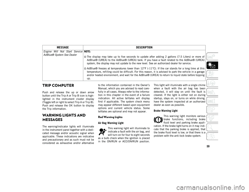
Air Bag Warning Light
This warning light will illuminate to
indicate a fault with the air bag, and
will turn on for four to eight seconds
as a bulb check when the ignition is placed
in the ON/RUN or ACC/ON/RUN position. This light will illuminate with a single chime
when a fault with the air bag has been
detected, it will stay on until the fault is
cleared. If the light is either not on during
startup, stays on, or turns on while driving,
have the system inspected at an authorized
dealer as soon as possible.
Brake Warning Light
This warning light monitors various
brake functions, including brake
fluid level and parking brake appli
-
cation. If the brake light turns on it may indi -
cate that the parking brake is applied, that
the brake fluid level is low, or that there is a
problem with the anti-lock brake system.
Engine Will Not Start Service
AdBlue® System See Dealer
NOTE:
The display may take up to five seconds to update after adding 2 gallons (7.5 Liters) or more of
AdBlue® (UREA) to the AdBlue® (UREA) tank. If you have a fault related to the AdBlue® (UREA)
system, the display may not update to the new level. See an authorized dealer for service.
AdBlue® freezes at temperatures lower than 12°F (-11°C). If the car stands for a long time at this
temperature, refilling could be difficult. For this reason, it is advised to park the vehicle in a garage
and/or heated environment, and wait for the AdBlue® (UREA) to return to liquid state before topping
up.
MESSAGE
DESCRIPTION
2020_JEEP_M6_UG_UK.book Page 59
Page 62 of 328
GETTING TO KNOW YOUR INSTRUMENT PANEL
60
If the light remains on when the parking
brake has been disengaged, and the fluid
level is at the full mark on the master
cylinder reservoir, it indicates a possible
brake hydraulic system malfunction or that a
problem with the Brake Booster has been
detected by the Anti-Lock Brake System
(ABS) / Electronic Stability Control (ESC)
system. In this case, the light will remain on
until the condition has been corrected. If the
problem is related to the brake booster, the
ABS pump will run when applying the brake,
and a brake pedal pulsation may be felt
during each stop.
The dual brake system provides a reserve
braking capacity in the event of a failure to a
portion of the hydraulic system. A leak in
either half of the dual brake system is indi-
cated by the Brake Warning Light, which will
turn on when the brake fluid level in the
master cylinder has dropped below a speci -
fied level.
The light will remain on until the cause is
corrected.
NOTE:
The light may flash momentarily during
sharp cornering maneuvers, which change
fluid level conditions. The vehicle should
have service performed, and the brake fluid
level checked. If brake failure is indicated, immediate
repair is necessary.
Vehicles equipped with the Anti-Lock Brake
System (ABS) are also equipped with Elec
-
tronic Brake Force Distribution (EBD). In the
event of an EBD failure, the Brake Warning
Light will turn on along with the ABS Light.
Immediate repair to the ABS system is
required.
Operation of the Brake Warning Light can be
checked by turning the ignition switch from
the OFF position to the ON/RUN position.
The light should illuminate for approximately
four seconds. The light should then turn off
unless the parking brake is applied or a brake
fault is detected. If the light does not illumi -
nate, have the light inspected by an autho -
rized dealer.
The light also will turn on when the parking
brake is applied with the ignition switch in
the ON/RUN position. NOTE:
This light shows only that the parking brake
is applied. It does not show the degree of
brake application.
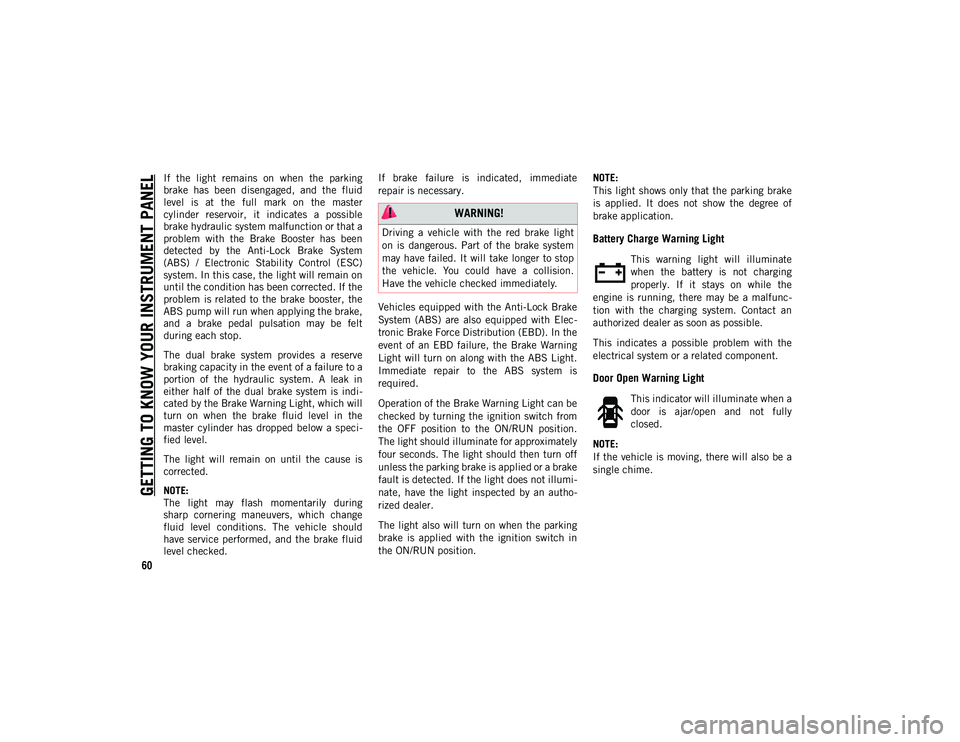
Battery Charge Warning Light
This warning light will illuminate
when the battery is not charging
properly. If it stays on while the
engine is running, there may be a malfunc -
tion with the charging system. Contact an
authorized dealer as soon as possible.
This indicates a possible problem with the
electrical system or a related component.
Door Open Warning Light
This indicator will illuminate when a
door is ajar/open and not fully
closed.
NOTE:
If the vehicle is moving, there will also be a
single chime.
WARNING!
Driving a vehicle with the red brake light
on is dangerous. Part of the brake system
may have failed. It will take longer to stop
the vehicle. You could have a collision.
Have the vehicle checked immediately.
2020_JEEP_M6_UG_UK.book Page 60