ESP JEEP COMPASS 2021 Owner handbook (in English)
[x] Cancel search | Manufacturer: JEEP, Model Year: 2021, Model line: COMPASS, Model: JEEP COMPASS 2021Pages: 328, PDF Size: 8.85 MB
Page 160 of 328
STARTING AND OPERATING
158
“SDW Not Available” — This message is
displayed if the Side Distance Warning
system is not available. The failed operation
of the system might be due to the insuffi-
cient voltage from the battery or other fail -
ures on the electrical system. Contact an
authorized dealer as soon as possible to have
the electrical system checked.
Operation With A Trailer
The system is automatically deactivated
when the trailer's electric plug is inserted in
the vehicle's tow hook socket. The rear
sensors are automatically reactivated when
the trailer's cable plug is removed.
ParkSense Usage Precautions
Some conditions may influence the perfor -
mance of the Side Distance Warning System:
NOTE:
Ensure that the front and rear bumper are
free of snow, ice, mud, dirt and debris to
keep the ParkSense system operating
properly.
Construction equipment, large trucks, and
other vibrations could affect the perfor -
mance of ParkSense.
When you turn ParkSense off, the message
to appear in the instrument cluster display
will read “PARKSENSE OFF.” Further -
more, once you turn ParkSense off, it
remains off until you turn it on again, even
if you cycle the ignition key.
ParkSense, when on, will reduce the
volume of the radio when it is sounding a
tone.
Clean the ParkSense sensors regularly,
taking care not to scratch or damage them.
The sensors must not be covered with ice,
snow, slush, mud, dirt or debris. Failure to
do so can result in the system not working
properly. The ParkSense system might not
detect an obstacle behind or in front of the
fascia/bumper, or it could provide a false
indication that an obstacle is behind or in
front of the fascia/bumper.
The presence of a tow hook without a
trailer may interfere with the correct oper -
ation of the parking sensors. Before using
the ParkSense system, it is recommended
to remove the removable tow hook ball
assembly and any attachments from the
vehicle when it is not used for towing oper -
ations. If you wish to leave the tow hook
fitted without towing a trailer, it is advis- able to contact an authorized dealer for
the ParkSense system update operations
because the tow hook could be detected
as an obstacle by the central sensors.
WARNING!
Drivers must be careful when backing up
even when using ParkSense. Always
check carefully behind your vehicle, look
behind you, and be sure to check for
pedestrians, animals, other vehicles,
obstructions, and blind spots before
backing up. You are responsible for
safety and must continue to pay atten
-
tion to your surroundings. Failure to do
so can result in serious injury or death.
Before using ParkSense, it is strongly
recommended that the ball mount and
hitch ball assembly is disconnected from
the vehicle when the vehicle is not used
for towing. Failure to do so can result in
injury or damage to vehicles or obstacles
because the hitch ball will be much
closer to the obstacle than the rear fascia
when the loudspeaker sounds the contin -
uous tone. Also, the sensors could detect
the ball mount and hitch ball assembly,
depending on its size and shape, giving
a false indication that an obstacle is
behind the vehicle.
2020_JEEP_M6_UG_UK.book Page 158
Page 161 of 328
159
PARKSENSE ACTIVE PARK
ASSIST SYSTEM — IF
EQUIPPED
The ParkSense Active Park Assist system is
intended to assist the driver during Parallel,
Perpendicular, and Parallel Park Exit maneu-
vers by identifying a proper parking space,
providing audible/visual instructions, and
controlling the steering wheel. The Park -
Sense Active Park Assist system is defined
as “semi-automatic” since the driver main -
tains control of the accelerator, gear selector and brakes. Depending on the driver's
parking maneuver selection, the ParkSense
Active Park Assist system is capable of
maneuvering a vehicle into a parallel or a
perpendicular parking space on either side
(i.e., driver side or passenger side), as well as
exiting a parallel parking space.
NOTE:
The driver is always responsible for
controlling the vehicle, responsible for any
surrounding objects, and must intervene
as required.
The system is provided to assist the driver
and not to substitute the driver.
During a semi-automatic maneuver, if the
driver touches the steering wheel after
being instructed to remove their hands
from the steering wheel, the system will
cancel, and the driver will be required to
manually complete the parking maneuver.
The system may not work in all conditions
(e.g. environmental conditions such as
heavy rain, snow, etc., or if searching for a
parking space that has surfaces that will
absorb the ultrasonic sensor waves).
New vehicles from the dealer must have at
least 30 miles (48 km) accumulated
before the ParkSense Active Park Assist
system is fully calibrated and performs
accurately. This is due to the system’s
dynamic vehicle calibration to improve the
performance of the feature. The system
will also continuously perform the
dynamic vehicle calibration to account for
differences such as over or under inflated
tires and new tires.
Enabling And Disabling The ParkSense
Active Park Assist System
The ParkSense Active Park Assist system can
be enabled and disabled with the ParkSense
Active Park Assist switch, located on the
switch panel below the Uconnect display.
To enable the ParkSense Active Park
Assist system, push the ParkSense
Active Park Assist switch once (LED
turns on).
To disable the ParkSense Active Park Assist
system, push the ParkSense Active Park
Assist switch again (LED turns off).
CAUTION!
ParkSense is only a parking aid and it is
unable to recognize every obstacle,
including small obstacles. Parking curbs
might be temporarily detected or not
detected at all. Obstacles located above
or below the sensors will not be detected
when they are in close proximity.
The vehicle must be driven slowly when
using ParkSense in order to be able to
stop in time when an obstacle is
detected. It is recommended that the
driver looks over his/her shoulder when
using ParkSense.
2020_JEEP_M6_UG_UK.book Page 159
Page 167 of 328
165
REFUELING THE VEHICLE
The Capless Fuel System uses a flapper
placed at the filler pipe of the fuel tank; it
opens and closes automatically upon inser-
tion/extraction of the fuel nozzle. In certain
countries, the Capless Fuel System is
designed so that it prevents the filling of an
incorrect type of fuel.
1. Unlock the fuel filler door by pushing the unlock button on the key fob or the
unlock button on the driver-side door
trim panel.
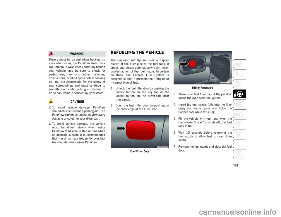
2. Open the fuel filler door by pushing on the outer edge of the Fuel Door.
Fuel Filler Door Filling Procedure
3. There is no fuel filler cap. A flapper door inside the pipe seals the system.
4. Insert the fuel nozzle fully into the filler pipe; the nozzle opens and holds the
flapper door while refueling.
5. Fill the vehicle with fuel, and when the fuel nozzle “clicks” or shuts off, the fuel
tank is full.
6. Wait 10 seconds before removing the fuel nozzle to allow fuel to drain from
nozzle.
7. Remove the fuel nozzle and close the fuel door.
WARNING!
Drivers must be careful when backing up
even when using the ParkView Rear Back
Up Camera. Always check carefully behind
your vehicle, and be sure to check for
pedestrians, animals, other vehicles,
obstructions, or blind spots before backing
up. You are responsible for the safety of
your surroundings and must continue to
pay attention while backing up. Failure to
do so can result in serious injury or death.
CAUTION!
To avoid vehicle damage, ParkView
should only be used as a parking aid. The
ParkView camera is unable to view every
obstacle or object in your drive path.
To avoid vehicle damage, the vehicle
must be driven slowly when using
ParkView to be able to stop in time when
an obstacle is seen. It is recommended
that the driver look frequently over his/
her shoulder when using ParkView.
2020_JEEP_M6_UG_UK.book Page 165
Page 195 of 328
193
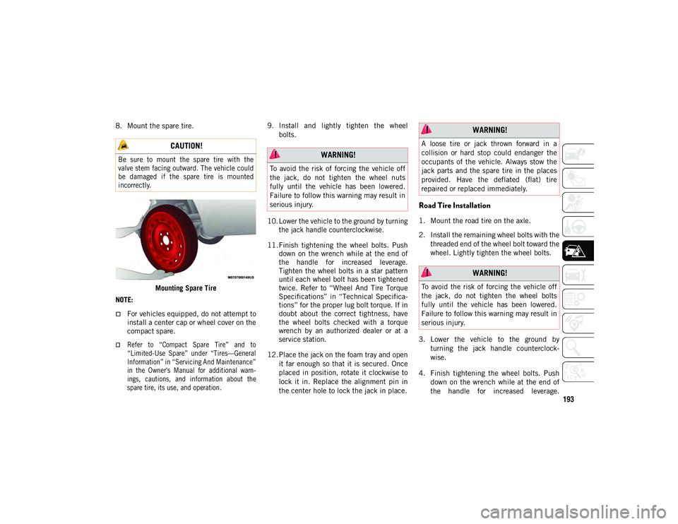
8. Mount the spare tire.Mounting Spare Tire
NOTE:
For vehicles equipped, do not attempt to install a center cap or wheel cover on the
compact spare.
Refer to “Compact Spare Tire” and to
“Limited-Use Spare” under “Tires—General
Information” in “Servicing And Maintenance”
in the Owner's Manual for additional warn- ings, cautions, and information about thespare tire, its use, and operation.
9. Install and lightly tighten the wheel
bolts.
10. Lower the vehicle to the ground by turning the jack handle counterclockwise.
11. Finish tightening the wheel bolts. Push down on the wrench while at the end of
the handle for increased leverage.
Tighten the wheel bolts in a star pattern
until each wheel bolt has been tightened
twice. Refer to “Wheel And Tire Torque
Specifications” in “Technical Specifica -
tions” for the proper lug bolt torque. If in
doubt about the correct tightness, have
the wheel bolts checked with a torque
wrench by an authorized dealer or at a
service station.
12. Place the jack on the foam tray and open it far enough so that it is secured. Once
placed in position, rotate it clockwise to
lock it in. Replace the alignment pin in
the center hole to lock the jack in place.
Road Tire Installation
1. Mount the road tire on the axle.
2. Install the remaining wheel bolts with thethreaded end of the wheel bolt toward the
wheel. Lightly tighten the wheel bolts.
3. Lower the vehicle to the ground by turning the jack handle counterclock -
wise.
4. Finish tightening the wheel bolts. Push down on the wrench while at the end of
the handle for increased leverage.
CAUTION!
Be sure to mount the spare tire with the
valve stem facing outward. The vehicle could
be damaged if the spare tire is mounted
incorrectly.
WARNING!
To avoid the risk of forcing the vehicle off
the jack, do not tighten the wheel nuts
fully until the vehicle has been lowered.
Failure to follow this warning may result in
serious injury.
WARNING!
A loose tire or jack thrown forward in a
collision or hard stop could endanger the
occupants of the vehicle. Always stow the
jack parts and the spare tire in the places
provided. Have the deflated (flat) tire
repaired or replaced immediately.
WARNING!
To avoid the risk of forcing the vehicle off
the jack, do not tighten the wheel bolts
fully until the vehicle has been lowered.
Failure to follow this warning may result in
serious injury.
2020_JEEP_M6_UG_UK.book Page 193
Page 200 of 328
IN CASE OF EMERGENCY
198
(Continued)
Sealing A Tire With Tire Service Kit
Whenever You Stop To Use Tire Service Kit:
1. Pull over to a safe location and turn onthe vehicle’s Hazard Warning flashers.
2. Verify that the valve stem (on the wheel with the deflated tire) is in a position that
is near to the ground. This will allow the
Tire Service Kit Hose to reach the valve
stem and keep the Tire Service Kit flat on
the ground. This will provide the best
positioning of the kit when injecting the
sealant into the deflated tire and running
the air pump. Move the vehicle as neces -
sary to place the valve stem in this posi -
tion before proceeding. 3. Place the transmission in PARK and
cycle the ignition in the OFF position.
4. Apply the parking brake.
Setting Up To Use Tire Service Kit:
1. Uncoil the Sealant Hose and then remove the cap from the fitting at the end of the
hose.
2. Place the Tire Service Kit flat on the ground next to the deflated tire.
3. Remove the cap from the valve stem and then screw the fitting at the end of the
Sealant Hose onto the valve stem.
4. Uncoil the Power Plug and insert the plug into the vehicle’s 12 Volt power outlet.
NOTE:
Do not remove foreign objects (e.g., screws
or nails) from the tire.
Injecting Tire Service Kit Sealant Into The
Deflated Tire:
1. Always start the vehicle before turning the Tire Service Kit on.
2. Ensure the Mode Select Knob is to the Sealant Mode position.
If the wheel has any damage.
If you are unsure of the condition ofthe tire or the wheel.
Keep Tire Service Kit away from open
flames or heat source.
A loose Tire Service Kit thrown forward in
a collision or hard stop could endanger
the occupants of the vehicle. Always
stow the Tire Service Kit in the place
provided. Failure to follow these warn -
ings can result in injuries that are serious
or fatal to you, your passengers, and
others around you.
Take care not to allow the contents of
Tire Service Kit to come in contact with
hair, eyes, or clothing. Tire Service Kit
sealant is harmful if inhaled, swallowed,
or absorbed through the skin. It causes
skin, eye, and respiratory irritation.
Flush immediately with plenty of water if
there is any contact with eyes or skin.
Change clothing as soon as possible, if
there is any contact with clothing.
WARNING! (Continued)
Tire Service Kit Sealant solution
contains latex. In case of an allergic
reaction or rash, consult a physician
immediately. Keep Tire Service Kit out
of reach of children. If swallowed, rinse
mouth immediately with plenty of water
and drink plenty of water. Do not induce
vomiting! Consult a physician immedi -
ately.
WARNING! (Continued)
2020_JEEP_M6_UG_UK.book Page 198
Page 203 of 328
201
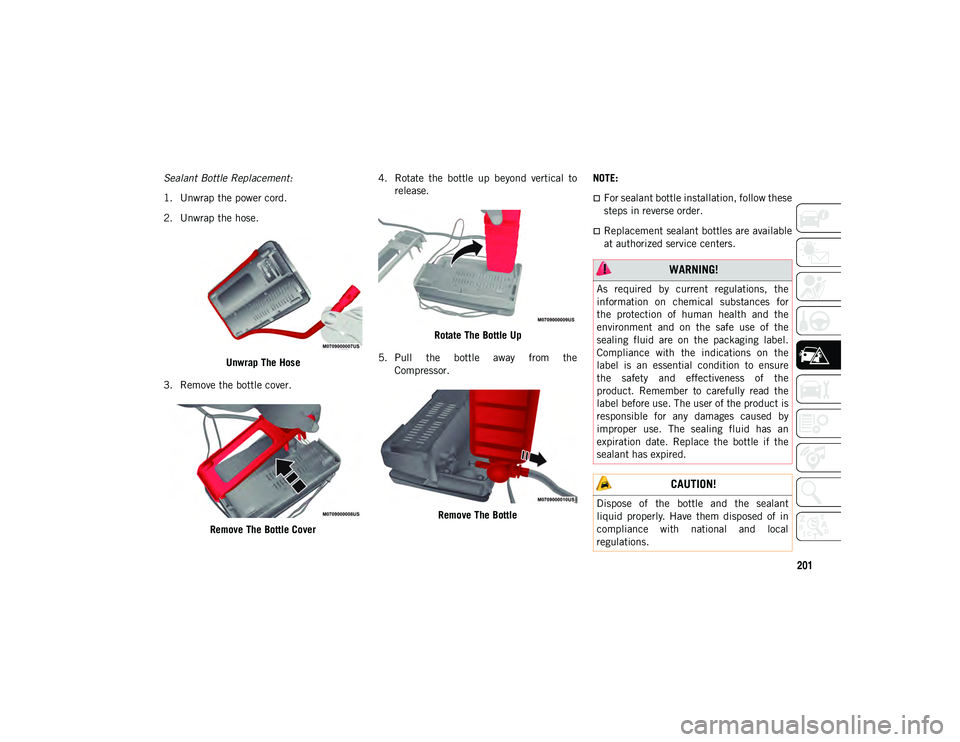
Sealant Bottle Replacement:
1. Unwrap the power cord.
2. Unwrap the hose.Unwrap The Hose
3. Remove the bottle cover.
Remove The Bottle Cover 4. Rotate the bottle up beyond vertical to
release.
Rotate The Bottle Up
5. Pull the bottle away from the Compressor.
Remove The Bottle NOTE:
For sealant bottle installation, follow these
steps in reverse order.
Replacement sealant bottles are available
at authorized service centers.
WARNING!
As required by current regulations, the
information on chemical substances for
the protection of human health and the
environment and on the safe use of the
sealing fluid are on the packaging label.
Compliance with the indications on the
label is an essential condition to ensure
the safety and effectiveness of the
product. Remember to carefully read the
label before use. The user of the product is
responsible for any damages caused by
improper use. The sealing fluid has an
expiration date. Replace the bottle if the
sealant has expired.
CAUTION!
Dispose of the bottle and the sealant
liquid properly. Have them disposed of in
compliance with national and local
regulations.
2020_JEEP_M6_UG_UK.book Page 201
Page 213 of 328
211
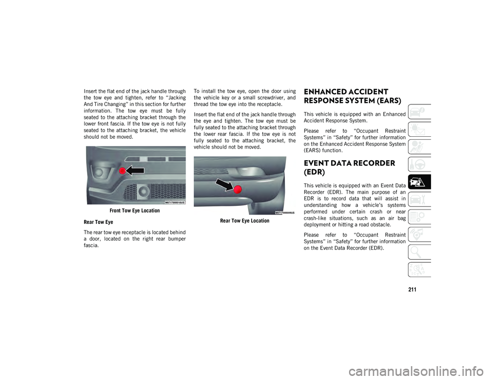
Insert the flat end of the jack handle through
the tow eye and tighten, refer to “Jacking
And Tire Changing” in this section for further
information. The tow eye must be fully
seated to the attaching bracket through the
lower front fascia. If the tow eye is not fully
seated to the attaching bracket, the vehicle
should not be moved.Front Tow Eye Location
Rear Tow Eye
The rear tow eye receptacle is located behind
a door, located on the right rear bumper
fascia. To install the tow eye, open the door using
the vehicle key or a small screwdriver, and
thread the tow eye into the receptacle.
Insert the flat end of the jack handle through
the eye and tighten. The tow eye must be
fully seated to the attaching bracket through
the lower rear fascia. If the tow eye is not
fully seated to the attaching bracket, the
vehicle should not be moved.
Rear Tow Eye LocationENHANCED ACCIDENT
RESPONSE SYSTEM (EARS)
This vehicle is equipped with an Enhanced
Accident Response System.
Please refer to “Occupant Restraint
Systems” in “Safety” for further information
on the Enhanced Accident Response System
(EARS) function.
EVENT DATA RECORDER
(EDR)
This vehicle is equipped with an Event Data
Recorder (EDR). The main purpose of an
EDR is to record data that will assist in
understanding how a vehicle’s systems
performed under certain crash or near
crash-like situations, such as an air bag
deployment or hitting a road obstacle.
Please refer to “Occupant Restraint
Systems” in “Safety” for further information
on the Event Data Recorder (EDR).
2020_JEEP_M6_UG_UK.book Page 211
Page 214 of 328
212
SERVICING AND MAINTENANCE
SCHEDULED SERVICING
Correct servicing is crucial for guaranteeing a
long life for the car under the best condi-
tions. For this reason, Jeep has planned a
series of checks and services at fixed
distance intervals and, where provided, at
fixed time intervals, as described in the
Scheduled Servicing plan. To keep the car’s
efficiency in tip-top condition, in the
following Scheduled Service plan pages a
few additional checks are listed that should
be carried out more frequently with respect
to the normal coupon redemption schedule.
Scheduled Servicing is offered by all autho -
rized dealerships according to fixed time or
mileage intervals. If, during each operation,
in addition to the ones scheduled, the need
arises for further replacements or repairs,
these may be carried out with the owner's
explicit agreement only.
The technicians at your dealership know your
vehicle best, and have access to factory
trained information, genuine Mopar parts,
and specially designed electronic and
mechanical tools that can help prevent
future costly repairs. If your car is used
frequently for towing, the interval between
one scheduled servicing operation and the next should be reduced. More frequent main
-
tenance may be needed for vehicles in severe
operating conditions, such as dusty areas
and very short trip driving.
NOTE:
Scheduled Servicing interventions are set
out by the Manufacturer. Failure to have
them carried out may invalidate the
warranty. It is advised to inform an autho -
rized dealership of any small operating irreg -
ularities without waiting for the next service.
1.4L Gasoline Engine
NOTE:
Under no circumstances should oil change
intervals exceed 9,000 miles (15,000 km)
or 12 months, whichever comes first.
Once A Month Or Before A Long Trip
Check engine oil level.
Check windshield washer fluid level.
Check tire pressure and look for unusual
wear or damage. Rotate tires at the first
sign of irregular wear, even if it occurs
before the oil indicator system turns on.
Check the fluid levels of the coolant reser -
voir and brake master cylinder, fill as
needed.
Check function of all interior and exterior
lights.
At Each Oil Change
Change oil and filter.
Rotate the tires. Rotate at the first sign of
irregular wear, even if it occurs before the
oil indicator system turns on.
Inspect battery and clean and tighten
terminals as required.
Inspect the CV/Universal joints.
Inspect brake pads, shoes, rotors, drums,
hoses and park brake.
Inspect engine cooling system protection
and hoses.
Inspect exhaust system.
Inspect engine air cleaner if using in dusty
or off-road conditions. Replace air cleaner
filter, if necessary.
Refer to the “Maintenance Plan” on the
following page for the required maintenance
intervals.
2020_JEEP_M6_UG_UK.book Page 212
Page 234 of 328
SERVICING AND MAINTENANCE
232
RAISING THE VEHICLE
In the case where it is necessary to raise the
vehicle, go to an authorized dealer or service
station.
TIRES
Tires — General Information
Tire Pressure
Proper tire inflation pressure is essential to
the safe and satisfactory operation of your
vehicle. Four primary areas are affected by
improper tire pressure:
Safety
Fuel Economy
Tread Wear
Ride Comfort And Vehicle StabilitySafety
Both underinflation and overinflation affect
the stability of the vehicle and can produce
a feeling of sluggish response or over respon-
siveness in the steering.
NOTE:
Unequal tire pressures from side to side
may cause erratic and unpredictable
steering response.
Unequal tire pressure from side to side
may cause the vehicle to drift left or right.
Fuel Economy
Underinflated tires will increase tire rolling
resistance resulting in higher fuel consump -
tion.
Tread Wear
Improper cold tire inflation pressures can
cause abnormal wear patterns and reduced
tread life, resulting in the need for earlier tire
replacement.
Ride Comfort And Vehicle Stability
Proper tire inflation contributes to a comfort -
able ride. Overinflation produces a jarring
and uncomfortable ride.
CAUTION!
If a transmission fluid leak occurs, visit an
authorized dealer immediately. Severe
transmission damage may occur. An
authorized dealer has the proper tools to
adjust the fluid level accurately. WARNING!
Improperly inflated tires are dangerous
and can cause collisions.
Underinflation increases tire flexing and
can result in overheating and tire failure.
Overinflation reduces a tire's ability to
cushion shock. Objects on the road and
chuckholes can cause damage that
result in tire failure.
Overinflated or underinflated tires can
affect vehicle handling and can fail
suddenly, resulting in loss of vehicle
control.
Unequal tire pressures can cause
steering problems. You could lose
control of your vehicle.
Unequal tire pressures from one side of
the vehicle to the other can cause the
vehicle to drift to the right or left.
Always drive with each tire inflated to the
recommended cold tire inflation pres-
sure.
2020_JEEP_M6_UG_UK.book Page 232
Page 235 of 328
233
Tire Inflation Pressures
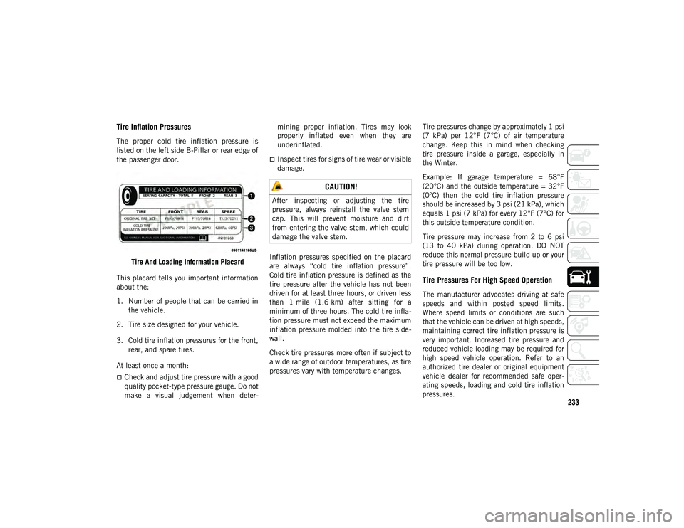
The proper cold tire inflation pressure is
listed on the left side B-Pillar or rear edge of
the passenger door.Tire And Loading Information Placard
This placard tells you important information
about the:
1. Number of people that can be carried in the vehicle.
2. Tire size designed for your vehicle.
3. Cold tire inflation pressures for the front, rear, and spare tires.
At least once a month:
Check and adjust tire pressure with a good
quality pocket-type pressure gauge. Do not
make a visual judgement when deter -mining proper inflation. Tires may look
properly inflated even when they are
underinflated.
Inspect tires for signs of tire wear or visible
damage.
Inflation pressures specified on the placard
are always “cold tire inflation pressure”.
Cold tire inflation pressure is defined as the
tire pressure after the vehicle has not been
driven for at least three hours, or driven less
than 1 mile (1.6 km) after sitting for a
minimum of three hours. The cold tire infla -
tion pressure must not exceed the maximum
inflation pressure molded into the tire side -
wall.
Check tire pressures more often if subject to
a wide range of outdoor temperatures, as tire
pressures vary with temperature changes. Tire pressures change by approximately 1 psi
(7 kPa) per 12°F (7°C) of air temperature
change. Keep this in mind when checking
tire pressure inside a garage, especially in
the Winter.
Example: If garage temperature = 68°F
(20°C) and the outside temperature = 32°F
(0°C) then the cold tire inflation pressure
should be increased by 3 psi (21 kPa), which
equals 1 psi (7 kPa) for every 12°F (7°C) for
this outside temperature condition.
Tire pressure may increase from 2 to 6 psi
(13 to 40 kPa) during operation. DO NOT
reduce this normal pressure build up or your
tire pressure will be too low.
Tire Pressures For High Speed Operation
The manufacturer advocates driving at safe
speeds and within posted speed limits.
Where speed limits or conditions are such
that the vehicle can be driven at high speeds,
maintaining correct tire inflation pressure is
very important. Increased tire pressure and
reduced vehicle loading may be required for
high speed vehicle operation. Refer to an
authorized tire dealer or original equipment
vehicle dealer for recommended safe oper
-
ating speeds, loading and cold tire inflation
pressures.
CAUTION!
After inspecting or adjusting the tire
pressure, always reinstall the valve stem
cap. This will prevent moisture and dirt
from entering the valve stem, which could
damage the valve stem.
2020_JEEP_M6_UG_UK.book Page 233