service JEEP COMPASS 2021 Owner handbook (in English)
[x] Cancel search | Manufacturer: JEEP, Model Year: 2021, Model line: COMPASS, Model: JEEP COMPASS 2021Pages: 328, PDF Size: 8.85 MB
Page 188 of 328
IN CASE OF EMERGENCY
186
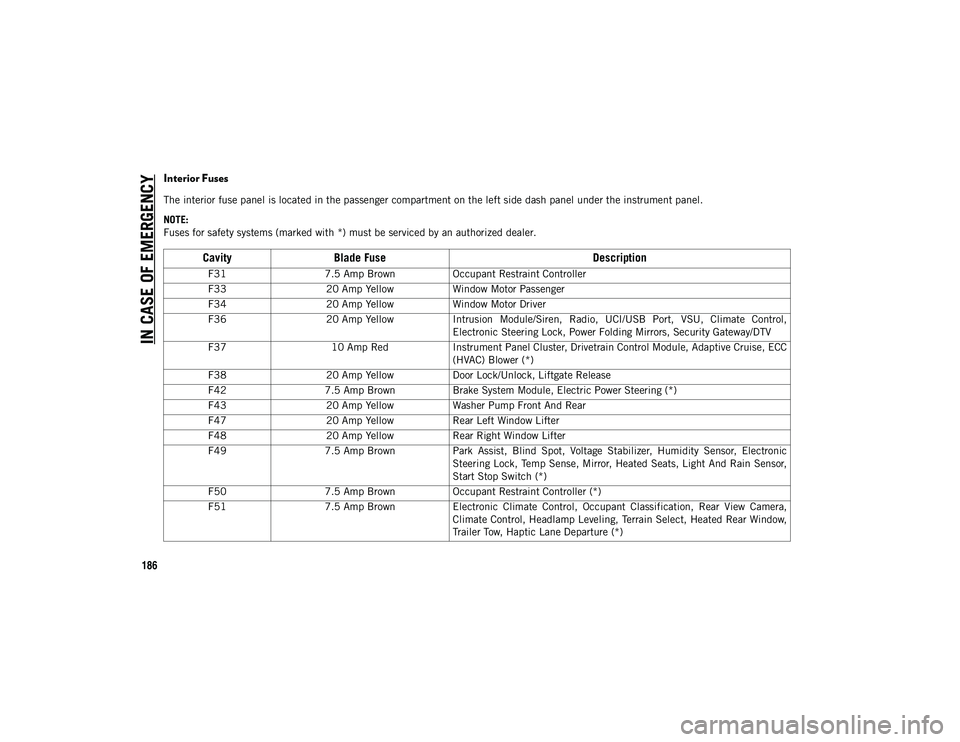
Interior Fuses
The interior fuse panel is located in the passenger compartment on the left side dash panel under the instrument panel.
NOTE:
Fuses for safety systems (marked with *) must be serviced by an authorized dealer.
CavityBlade Fuse Description
F317.5 Amp Brown Occupant Restraint Controller
F33 20 Amp Yellow Window Motor Passenger
F34 20 Amp Yellow Window Motor Driver
F36 20 Amp Yellow Intrusion Module/Siren, Radio, UCI/USB Port, VSU, Climate Control,
Electronic Steering Lock, Power Folding Mirrors, Security Gateway/DTV
F37 10 Amp RedInstrument Panel Cluster, Drivetrain Control Module, Adaptive Cruise, ECC
(HVAC) Blower (*)
F38 20 Amp Yellow Door Lock/Unlock, Liftgate Release
F42 7.5 Amp Brown Brake System Module, Electric Power Steering (*)
F43 20 Amp Yellow Washer Pump Front And Rear
F47 20 Amp Yellow Rear Left Window Lifter
F48 20 Amp Yellow Rear Right Window Lifter
F49 7.5 Amp Brown Park Assist, Blind Spot, Voltage Stabilizer, Humidity Sensor, Electronic
Steering Lock, Temp Sense, Mirror, Heated Seats, Light And Rain Sensor,
Start Stop Switch (*)
F50 7.5 Amp Brown Occupant Restraint Controller (*)
F51 7.5 Amp Brown Electronic Climate Control, Occupant Classification, Rear View Camera,
Climate Control, Headlamp Leveling, Terrain Select, Heated Rear Window,
Trailer Tow, Haptic Lane Departure (*)
2020_JEEP_M6_UG_UK.book Page 186
Page 189 of 328
187
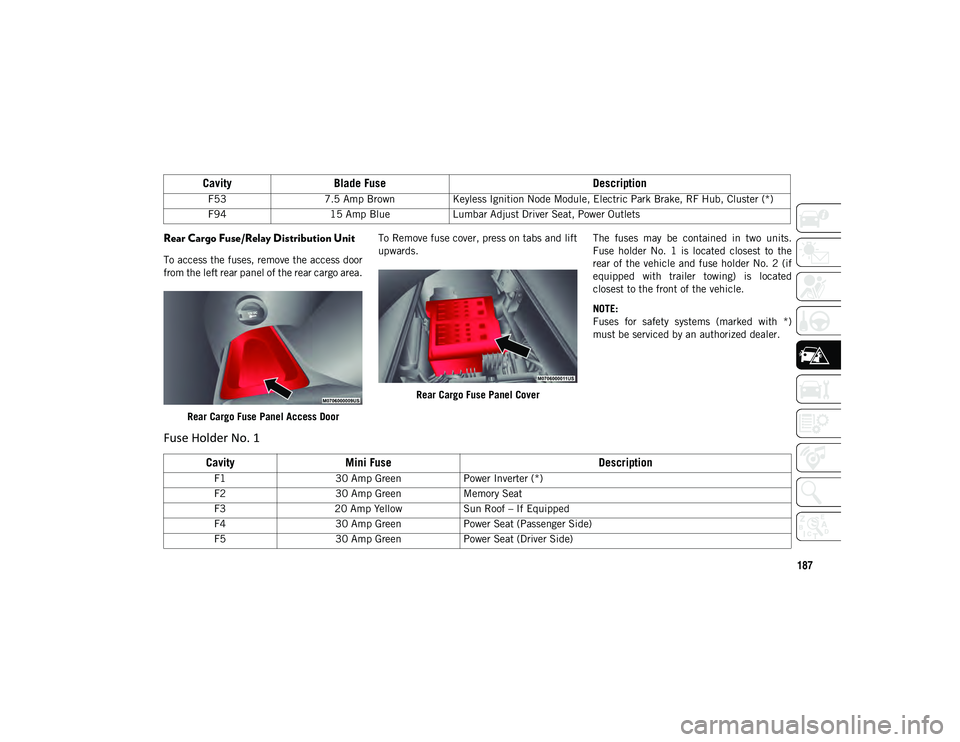
Rear Cargo Fuse/Relay Distribution Unit
To access the fuses, remove the access door
from the left rear panel of the rear cargo area.Rear Cargo Fuse Panel Access Door To Remove fuse cover, press on tabs and lift
upwards.
Rear Cargo Fuse Panel Cover The fuses may be contained in two units.
Fuse holder No. 1 is located closest to the
rear of the vehicle and fuse holder No. 2 (if
equipped with trailer towing) is located
closest to the front of the vehicle.
NOTE:
Fuses for safety systems (marked with *)
must be serviced by an authorized dealer.
F53
7.5 Amp Brown Keyless Ignition Node Module, Electric Park Brake, RF Hub, Cluster (*)
F94 15 Amp Blue Lumbar Adjust Driver Seat, Power Outlets
CavityBlade Fuse Description
Fuse Holder No. 1
CavityMini Fuse Description
F130 Amp Green Power Inverter (*)
F2 30 Amp Green Memory Seat
F3 20 Amp Yellow Sun Roof – If Equipped
F4 30 Amp Green Power Seat (Passenger Side)
F5 30 Amp Green Power Seat (Driver Side)
2020_JEEP_M6_UG_UK.book Page 187
Page 191 of 328
189
JACKING AND TIRE
CHANGING Jack Location/Spare Tire Stowage
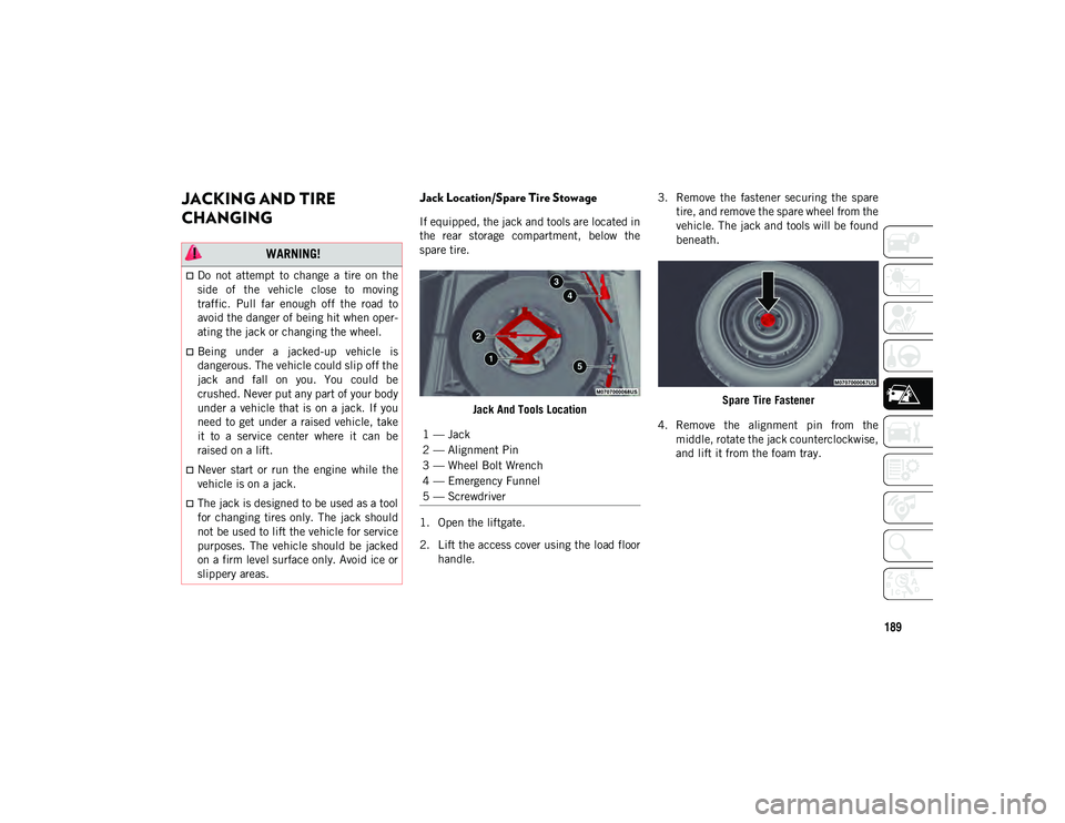
If equipped, the jack and tools are located in
the rear storage compartment, below the
spare tire.Jack And Tools Location
1. Open the liftgate.
2. Lift the access cover using the load floor handle. 3. Remove the fastener securing the spare
tire, and remove the spare wheel from the
vehicle. The jack and tools will be found
beneath.
Spare Tire Fastener
4. Remove the alignment pin from the middle, rotate the jack counterclockwise,
and lift it from the foam tray.
WARNING!
Do not attempt to change a tire on the
side of the vehicle close to moving
traffic. Pull far enough off the road to
avoid the danger of being hit when oper -
ating the jack or changing the wheel.
Being under a jacked-up vehicle is
dangerous. The vehicle could slip off the
jack and fall on you. You could be
crushed. Never put any part of your body
under a vehicle that is on a jack. If you
need to get under a raised vehicle, take
it to a service center where it can be
raised on a lift.
Never start or run the engine while the
vehicle is on a jack.
The jack is designed to be used as a tool
for changing tires only. The jack should
not be used to lift the vehicle for service
purposes. The vehicle should be jacked
on a firm level surface only. Avoid ice or
slippery areas.
1 — Jack
2 — Alignment Pin
3 — Wheel Bolt Wrench
4 — Emergency Funnel
5 — Screwdriver
2020_JEEP_M6_UG_UK.book Page 189
Page 193 of 328
191(Continued)
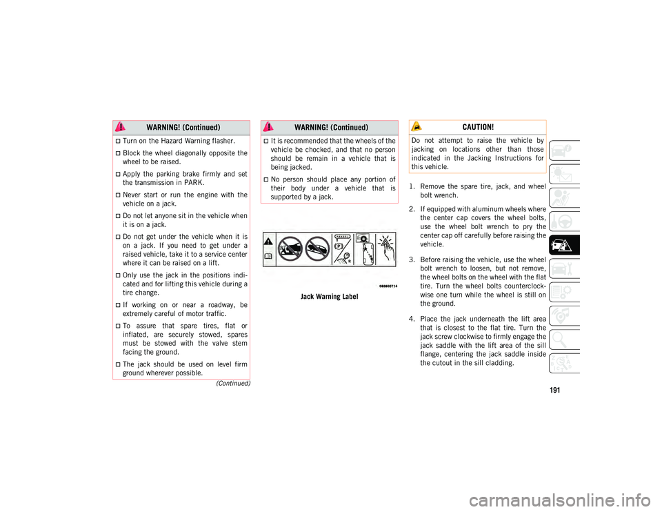
Jack Warning Label1. Remove the spare tire, jack, and wheel
bolt wrench.
2. If equipped with aluminum wheels where the center cap covers the wheel bolts,
use the wheel bolt wrench to pry the
center cap off carefully before raising the
vehicle.
3. Before raising the vehicle, use the wheel bolt wrench to loosen, but not remove,
the wheel bolts on the wheel with the flat
tire. Turn the wheel bolts counterclock -
wise one turn while the wheel is still on
the ground.
4. Place the jack underneath the lift area that is closest to the flat tire. Turn the
jack screw clockwise to firmly engage the
jack saddle with the lift area of the sill
flange, centering the jack saddle inside
the cutout in the sill cladding.
Turn on the Hazard Warning flasher.
Block the wheel diagonally opposite the
wheel to be raised.
Apply the parking brake firmly and set
the transmission in PARK.
Never start or run the engine with the
vehicle on a jack.
Do not let anyone sit in the vehicle when
it is on a jack.
Do not get under the vehicle when it is
on a jack. If you need to get under a
raised vehicle, take it to a service center
where it can be raised on a lift.
Only use the jack in the positions indi -
cated and for lifting this vehicle during a
tire change.
If working on or near a roadway, be
extremely careful of motor traffic.
To assure that spare tires, flat or
inflated, are securely stowed, spares
must be stowed with the valve stem
facing the ground.
The jack should be used on level firm
ground wherever possible.
WARNING! (Continued)
It is recommended that the wheels of the
vehicle be chocked, and that no person
should be remain in a vehicle that is
being jacked.
No person should place any portion of
their body under a vehicle that is
supported by a jack.
WARNING! (Continued) CAUTION!
Do not attempt to raise the vehicle by
jacking on locations other than those
indicated in the Jacking Instructions for
this vehicle.
2020_JEEP_M6_UG_UK.book Page 191
Page 195 of 328
193
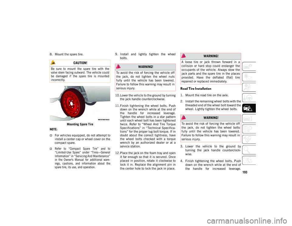
8. Mount the spare tire.Mounting Spare Tire
NOTE:
For vehicles equipped, do not attempt to install a center cap or wheel cover on the
compact spare.
Refer to “Compact Spare Tire” and to
“Limited-Use Spare” under “Tires—General
Information” in “Servicing And Maintenance”
in the Owner's Manual for additional warn- ings, cautions, and information about thespare tire, its use, and operation.
9. Install and lightly tighten the wheel
bolts.
10. Lower the vehicle to the ground by turning the jack handle counterclockwise.
11. Finish tightening the wheel bolts. Push down on the wrench while at the end of
the handle for increased leverage.
Tighten the wheel bolts in a star pattern
until each wheel bolt has been tightened
twice. Refer to “Wheel And Tire Torque
Specifications” in “Technical Specifica -
tions” for the proper lug bolt torque. If in
doubt about the correct tightness, have
the wheel bolts checked with a torque
wrench by an authorized dealer or at a
service station.
12. Place the jack on the foam tray and open it far enough so that it is secured. Once
placed in position, rotate it clockwise to
lock it in. Replace the alignment pin in
the center hole to lock the jack in place.
Road Tire Installation
1. Mount the road tire on the axle.
2. Install the remaining wheel bolts with thethreaded end of the wheel bolt toward the
wheel. Lightly tighten the wheel bolts.
3. Lower the vehicle to the ground by turning the jack handle counterclock -
wise.
4. Finish tightening the wheel bolts. Push down on the wrench while at the end of
the handle for increased leverage.
CAUTION!
Be sure to mount the spare tire with the
valve stem facing outward. The vehicle could
be damaged if the spare tire is mounted
incorrectly.
WARNING!
To avoid the risk of forcing the vehicle off
the jack, do not tighten the wheel nuts
fully until the vehicle has been lowered.
Failure to follow this warning may result in
serious injury.
WARNING!
A loose tire or jack thrown forward in a
collision or hard stop could endanger the
occupants of the vehicle. Always stow the
jack parts and the spare tire in the places
provided. Have the deflated (flat) tire
repaired or replaced immediately.
WARNING!
To avoid the risk of forcing the vehicle off
the jack, do not tighten the wheel bolts
fully until the vehicle has been lowered.
Failure to follow this warning may result in
serious injury.
2020_JEEP_M6_UG_UK.book Page 193
Page 196 of 328
IN CASE OF EMERGENCY
194
Tighten the wheel bolts in a star pattern
until each wheel bolt has been tightened
twice. Refer to “Wheel And Tire Torque
Specifications” in “Technical Specifica-
tions” for the proper lug bolt torque. If in
doubt about the correct tightness, have
them checked with a torque wrench by an
authorized dealer or service station.
5. Lower the jack until it is free. Remove the wheel blocks. Reassemble the lug
wrench to the jack assembly and stow it
in the spare tire area. Secure the
assembly using the means provided.
Release the parking brake before driving
the vehicle.
6. After 25 miles (40 km), check the wheel bolt torque with a torque wrench to
ensure that all wheel bolts are properly
seated against the wheel.
EC Declaration Of Conformance
1. The undersigned, Jaswant Singh, repre-
senting the Moonlight Tools Pvt. Ltd.,
herewith declares that the machinery
described below fulfills all the relevant
provisions of:
The EC-directive 2006/42/EC on Machinery 2. Description of machinery.
a. Generic Denomination: Pantograph
jack
b. Function: Lifting Motor Vehicle
3. Manufacturer Detail Moonlight Tools Pvt. Ltd.
Vill. Jaspalon, G.T. Road Doraha
Distt. Ludhiana (141421) Punjab (India)
Teh. PH. No. 01628 258302
4. Authorized Person to compile the tech -
nical file
Mr. Jaswant Singh DGM (QA & Dev.)
Moonlight Tools Pvt. Ltd.
Ludhiana
5. Reference standard: PF-90065 NOTE:
This declaration becomes invalid, if tech
-
nical or operational modifications are intro -
duced without the manufacture’s consent.
Follow operational manual and instructions
for use.
German Translation
Model
Code Model
Name Type Working
load
M6 (556) MPV MLF1 1250Kg
Date Place
Signature Seal
29–03–
2017 Doraha
Ludhiana
2020_JEEP_M6_UG_UK.book Page 194
Page 198 of 328
IN CASE OF EMERGENCY
196
NOTE:
The jack requires no adjustment.
The jack cannot be repaired, and in the
event of a fault, it must be replaced by
another genuine one.
No tool other than its cranking device may
be fitted on the jack.
TIRE SERVICE KIT — IF
EQUIPPED
Your vehicle may be equipped with a Tire
Service Kit. Small punctures up to 1/4 inch
(6 mm) in the tire tread can be sealed with
Tire Service Kit. Foreign objects (e.g., screws
or nails) should not be removed from the tire.
Tire Service Kit can be used in outside
temperatures down to approximately -4°F
(-20°C). This kit will provide a temporary tire
seal, allowing you to drive your vehicle up to
100 miles (160 km) with a maximum speed
of 50 mph (80 km/h).Tire Service Kit Storage
The Tire Service Kit is stowed under the load
floor behind the rear seat.
1. Open the liftgate.
2. Lift the access cover using the load floor
handle.
Load Floor Handle Tire Service Kit And Components And Operation
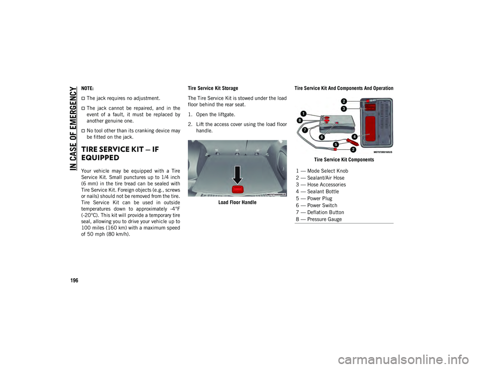
Tire Service Kit Components1 — Mode Select Knob
2 — Sealant/Air Hose
3 — Hose Accessories
4 — Sealant Bottle
5 — Power Plug
6 — Power Switch
7 — Deflation Button
8 — Pressure Gauge
2020_JEEP_M6_UG_UK.book Page 196
Page 199 of 328
197
(Continued)
Using The Mode Select Knob And Hoses
Your Tire Service Kit is equipped with the
following symbols to indicate the air or
sealant mode.
Selecting Air Mode
Push in the Mode Select Knob and turn
to this position for air pump operation on -
ly.
Selecting Sealant Mode
Push in the Mode Select Knob and turn
to this position to inject the Tire Service
Kit Sealant and to inflate the tire.
Using The Power Button
Push and release the Power Button once
to turn the Tire Service Kit on. Push and
release the Power Button again to turn
the Tire Service Kit off.
Using The Deflation Button
Push the Deflation Button to reduce the
air pressure in the tire if it becomes over
inflated. Tire Service Kit Usage Precautions
Replace the Tire Service Kit Sealant
Bottle prior to the expiration date (printed
at the lower right hand corner on the bottle
label) to assure optimum operation of the
system. Refer to “Sealant Bottle Replace-
ment” in this section.
The Sealant Bottle is a one tire application
use and needs to be replaced after each
use. Always replace these components
immediately from an authorized dealer.
When the Tire Service Kit sealant is in a
liquid form, clean water, and a damp cloth
will remove the material from the vehicle
or tire and wheel components. Once the
sealant dries, it can easily be peeled off
and properly discarded.
For optimum performance, make sure the
valve stem on the wheel is free of debris
before connecting the Tire Service Kit.
You can use the Tire Service Kit air pump
to inflate bicycle tires. The kit also comes
with two needles, located in the Accessory
Storage Compartment (on the bottom of
the air pump) for inflating sport balls,
rafts, or similar inflatable items. However,
use only the Air Pump and make sure the
Mode Select Knob is in the Air Mode when inflating such items to avoid injecting
sealant into them. The Tire Service Kit
Sealant is only intended to seal punctures
less than 1/4 inch (6 mm) diameter in the
tread of your vehicle.
Do not lift or carry the Tire Service Kit by
the hoses.
WARNING!
Do not attempt to seal a tire on the side
of the vehicle closest to traffic. Pull far
enough off the road to avoid the danger
of being hit when using the Tire Service
Kit.
Do not use Tire Service Kit or drive the
vehicle under the following circum
-
stances:
If the puncture in the tire tread is approximately 1/4 inch (6 mm) orlarger.
If the tire has any sidewall damage.
If the tire has any damage from driving with extremely low tire pres-
sure.
If the tire has any damage from driving on a flat tire.
2020_JEEP_M6_UG_UK.book Page 197
Page 200 of 328
IN CASE OF EMERGENCY
198
(Continued)
Sealing A Tire With Tire Service Kit
Whenever You Stop To Use Tire Service Kit:
1. Pull over to a safe location and turn onthe vehicle’s Hazard Warning flashers.
2. Verify that the valve stem (on the wheel with the deflated tire) is in a position that
is near to the ground. This will allow the
Tire Service Kit Hose to reach the valve
stem and keep the Tire Service Kit flat on
the ground. This will provide the best
positioning of the kit when injecting the
sealant into the deflated tire and running
the air pump. Move the vehicle as neces -
sary to place the valve stem in this posi -
tion before proceeding. 3. Place the transmission in PARK and
cycle the ignition in the OFF position.
4. Apply the parking brake.
Setting Up To Use Tire Service Kit:
1. Uncoil the Sealant Hose and then remove the cap from the fitting at the end of the
hose.
2. Place the Tire Service Kit flat on the ground next to the deflated tire.
3. Remove the cap from the valve stem and then screw the fitting at the end of the
Sealant Hose onto the valve stem.
4. Uncoil the Power Plug and insert the plug into the vehicle’s 12 Volt power outlet.
NOTE:
Do not remove foreign objects (e.g., screws
or nails) from the tire.
Injecting Tire Service Kit Sealant Into The
Deflated Tire:
1. Always start the vehicle before turning the Tire Service Kit on.
2. Ensure the Mode Select Knob is to the Sealant Mode position.
If the wheel has any damage.
If you are unsure of the condition ofthe tire or the wheel.
Keep Tire Service Kit away from open
flames or heat source.
A loose Tire Service Kit thrown forward in
a collision or hard stop could endanger
the occupants of the vehicle. Always
stow the Tire Service Kit in the place
provided. Failure to follow these warn -
ings can result in injuries that are serious
or fatal to you, your passengers, and
others around you.
Take care not to allow the contents of
Tire Service Kit to come in contact with
hair, eyes, or clothing. Tire Service Kit
sealant is harmful if inhaled, swallowed,
or absorbed through the skin. It causes
skin, eye, and respiratory irritation.
Flush immediately with plenty of water if
there is any contact with eyes or skin.
Change clothing as soon as possible, if
there is any contact with clothing.
WARNING! (Continued)
Tire Service Kit Sealant solution
contains latex. In case of an allergic
reaction or rash, consult a physician
immediately. Keep Tire Service Kit out
of reach of children. If swallowed, rinse
mouth immediately with plenty of water
and drink plenty of water. Do not induce
vomiting! Consult a physician immedi -
ately.
WARNING! (Continued)
2020_JEEP_M6_UG_UK.book Page 198
Page 201 of 328
199
3. After pushing the Power Button, thesealant (white fluid) will flow from the
Sealant Bottle through the Sealant Hose
and into the tire.
NOTE:
Sealant may leak out through the puncture in
the tire.
If the sealant (white fluid) does not flow within
0 – 10 seconds through the Sealant Hose:
1. Push the Power Button to turn the Tire Service Kit off. Disconnect the Sealant
Hose from the valve stem. Make sure the
valve stem is free of debris. Reconnect
the Sealant Hose to the valve stem.
Check that the Mode Select Knob is in
the Sealant Mode position and not Air
Mode. Push the Power Button to turn the
Tire Service Kit on.
2. Connect the Power Plug to a different 12 Volt power outlet in your vehicle or
another vehicle, if available. Make sure
the vehicle is running before turning the
Tire Service Kit on.
3. The Sealant Bottle may be empty due to previous use. Call for assistance. If the sealant (white fluid) does flow through the
Sealant Hose:
1. Continue to operate the pump until
sealant is no longer flowing through
hose (typically takes 30 - 70 seconds).
As the sealant flows through the Sealant
Hose, the Pressure Gauge can read as
high as 70 psi (4.8 Bar). The Pressure
Gauge will decrease quickly from
approximately 70 psi (4.8 Bar) to the
actual tire pressure when the Sealant
Bottle is empty.
2. The pump will start to inject air into the tire immediately after the Sealant Bottle
is empty. Continue to operate the pump
and inflate the tire to the cold tire infla -
tion pressure found on the tire and
loading information label located in the
driver-side door opening. Check the tire
pressure by looking at the Pressure
Gauge.
If the tire does not inflate to at least 26 psi (1.8
Bar) pressure within 15 minutes:
The tire is too badly damaged. Do not
attempt to drive the vehicle further. Call
for assistance. If the tire inflates to the recommended pressure
or is at least 26 psi (1.8 Bar) pressure within
15 minutes:
NOTE:
If the tire becomes over-inflated, push the
Deflation Button to reduce the tire pressure
to the recommended inflation pressure
before continuing.
1. Push the Power Button to turn off the
Tire Service Kit.
2. Remove the speed limit label from the Tire Service Kit and place sticker on the
steering wheel.
3. Immediately disconnect the Sealant Hose from the valve stem, reinstall the
cap on the fitting at the end of the hose,
and place the Tire Service Kit in the
vehicle storage location. Proceed to
“Drive Vehicle.”
Drive Vehicle:
Immediately after injecting sealant and
inflating the tire, drive the vehicle 5 miles
(8 km) or 10 minutes to ensure distribution
of the Tire Service Kit Sealant within the tire.
Do not exceed 50 mph (80 km/h).
2020_JEEP_M6_UG_UK.book Page 199