technical specifications JEEP COMPASS 2021 Owner handbook (in English)
[x] Cancel search | Manufacturer: JEEP, Model Year: 2021, Model line: COMPASS, Model: JEEP COMPASS 2021Pages: 328, PDF Size: 8.85 MB
Page 7 of 328
GETTING TO KNOW YOUR VEHICLE
GETTING TO KNOW YOUR INSTRUMENT PANEL SAFETY
STARTING AND OPERATING IN CASE OF EMERGENCY
SERVICING AND MAINTENANCE TECHNICAL SPECIFICATIONS MULTIMEDIA
CUSTOMER ASSISTANCE INDEX
2020_JEEP_M6_UG_UK.book Page 5
Page 12 of 328
10
DEALER SERVICE ................................ 227
Air Conditioner Maintenance.......... 227
Wiper Blades ............................... 228
Exhaust System ........................... 228
Cooling System ............................ 229
Brake System .............................. 230
Manual Transmission — If
Equipped ..................................... 231 Automatic Transmission ................ 231
RAISING THE VEHICLE .......................... 232TIRES ................................................. 232
Tires — General Information ......... 232
Tire Types .................................... 236
Spare Tires — If Equipped ............ 237
Tire Chains (Traction Devices) ....... 239
Tire Rotation Recommendations .... 239
STORING THE VEHICLE ......................... 240
BODYWORK ......................................... 241
Preserving The Bodywork ............... 241
INTERIORS ......................................... 242
Seats And Fabric Parts .................. 242
Plastic And Coated Parts ............... 243
Leather Parts ............................... 243
Glass Surfaces ............................ 243
TECHNICAL SPECIFICATIONS
IDENTIFICATION DATA .......................... 244
Vehicle Identification Number ....... 244
WHEEL AND TIRE TORQUE
SPECIFICATIONS ..................................244
Torque Specifications ................... 244
DIMENSIONS .......................................245
WHEELS ..............................................247
WEIGHTS ............................................249
FUEL REQUIREMENTS — GASOLINE
ENGINE ...............................................250
1.4L Turbo Gasoline Engine .......... 250
Ethanol ....................................... 250
Materials Added To Fuel ............... 250
Gasoline/Oxygenate Blends............ 250
Fuel Icon Identification Compliant To
EN16942 .................................... 251 Fuel System Cautions ................... 252
Carbon Monoxide Warnings ........... 252
FUEL REQUIREMENTS — DIESEL
ENGINE ..............................................252
Diesel Engine .............................. 252
Fuel Icon Identification Compliant To
EN16942 .................................... 253
FLUID CAPACITIES ..............................254 FLUIDS AND LUBRICANTS .....................255
Engine ........................................ 255
Chassis ...................................... 259
FUEL CONSUMPTION AND CO2
EMISSIONS ........................................260 MOPAR ACCESSORIES .........................260
Authentic Accessories By Mopar .... 260
MULTIMEDIA
UCONNECT SYSTEMS ...........................262
CYBERSECURITY .................................262
UCONNECT 3 WITH 5–INCH DISPLAY — IF
EQUIPPED............................................263
Uconnect 3 With 5–inch Display At A
Glance .........................................263 Clock Setting ...............................263
Audio Setting ...............................263
Radio Operation ...........................264
USB/Audio Jack (AUX)/Bluetooth®
Operation .....................................265 Voice Text Reply (Not Compatible With
iPhone®) ....................................266 Apps — If Equipped......................267
UCONNECT 4 WITH 7-INCH DISPLAY ....267
Uconnect 4 At A Glance ...............267
Drag & Drop Menu Bar .................268
Radio ..........................................269
Media Hub — USB/Audio Jack (AUX) —
If Equipped ..................................270 Android Auto™ — If Equipped .......271
Apple CarPlay® Integration — If
Equipped .....................................272 Apps — If Equipped......................273
2020_JEEP_M6_UG_UK.book Page 10
Page 171 of 328
169
AdBlue® (UREA) — If Equipped
The vehicle is equipped with an UREA injec -
tion system and Selective Catalytic Reduc -
tion to meet emission standards. These two
systems ensure compliance with the diesel
emissions requirements; at the same time,
they ensure fuel-efficiency, handling, torque
and power. For messages and system warn -
ings, refer to the "Warning Lights And
Messages" in the "Getting To Know Your
Instrument Panel" section. AdBlue® (UREA)
is a very stable product with a long shelf life.
Stored at temperatures LOWER than 90°F
(32°C), it has a shelf life of at least one year.
For more information on the AdBlue® liquid
type, see the “Fluids and lubricants” in the
“Technical specifications” section. The
vehicle is equipped with an automatic
AdBlue® heating system when the engine
starts allowing the system to work correctly
at temperatures lower than 12°F (-11°C).
NOTE:
AdBlue® freezes at temperatures lower than
12 °F (-11 °C).
AdBlue® (UREA) Storage
AdBlue® (UREA) is considered a very stable
product with a long shelf life. If AdBlue®
(UREA) is kept in temperatures between 10°
and 90°F (-12° and 32°C), it will last a
minimum of one year.
AdBlue® (UREA) is subject to freezing at the
lowest temperatures. For example, AdBlue®
(UREA) may freeze at temperatures at or
below 12°F (-11°C). The system has been
designed to operate in this environment.
NOTE:
When working with AdBlue® (UREA), it is
important to know that:
Any containers or parts that come into
contact with AdBlue® (UREA) must be
AdBlue® (UREA) compatible (plastic or
stainless steel). Copper, brass, aluminum,
iron or non-stainless steel should be
avoided as they are subject to corrosion by
AdBlue® (UREA).
If AdBlue® (UREA) is spilled, it should be
wiped up completely.
Adding AdBlue® (UREA)
Preliminary Conditions
AdBlue® (UREA) freezes at temperatures
lower than 12°F (-11°C). If the car stands for
a long time at this temperature refilling
could be difficult. For this reason, it is
advised to park the vehicle in a garage and/
or heated environment and wait for the urea
to return to liquid state before topping up.
Proceed as follows:
Park the car on flat ground and stop the
engine by cycling the ignition to the OFF
position.
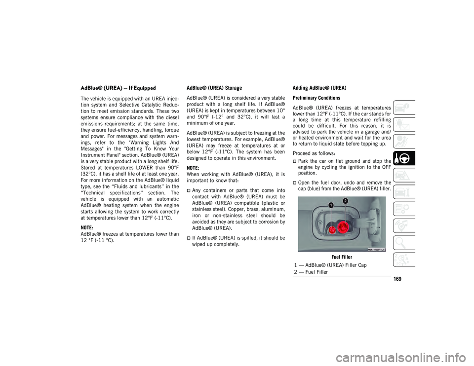
Open the fuel door, undo and remove the
cap (blue) from the AdBlue® (UREA) filler.
Fuel Filler
1 — AdBlue® (UREA) Filler Cap
2 — Fuel Filler
2020_JEEP_M6_UG_UK.book Page 169
Page 195 of 328
193
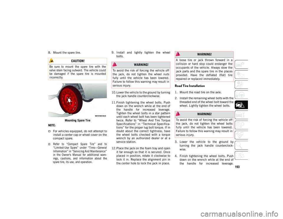
8. Mount the spare tire.Mounting Spare Tire
NOTE:
For vehicles equipped, do not attempt to install a center cap or wheel cover on the
compact spare.
Refer to “Compact Spare Tire” and to
“Limited-Use Spare” under “Tires—General
Information” in “Servicing And Maintenance”
in the Owner's Manual for additional warn- ings, cautions, and information about thespare tire, its use, and operation.
9. Install and lightly tighten the wheel
bolts.
10. Lower the vehicle to the ground by turning the jack handle counterclockwise.
11. Finish tightening the wheel bolts. Push down on the wrench while at the end of
the handle for increased leverage.
Tighten the wheel bolts in a star pattern
until each wheel bolt has been tightened
twice. Refer to “Wheel And Tire Torque
Specifications” in “Technical Specifica -
tions” for the proper lug bolt torque. If in
doubt about the correct tightness, have
the wheel bolts checked with a torque
wrench by an authorized dealer or at a
service station.
12. Place the jack on the foam tray and open it far enough so that it is secured. Once
placed in position, rotate it clockwise to
lock it in. Replace the alignment pin in
the center hole to lock the jack in place.
Road Tire Installation
1. Mount the road tire on the axle.
2. Install the remaining wheel bolts with thethreaded end of the wheel bolt toward the
wheel. Lightly tighten the wheel bolts.
3. Lower the vehicle to the ground by turning the jack handle counterclock -
wise.
4. Finish tightening the wheel bolts. Push down on the wrench while at the end of
the handle for increased leverage.
CAUTION!
Be sure to mount the spare tire with the
valve stem facing outward. The vehicle could
be damaged if the spare tire is mounted
incorrectly.
WARNING!
To avoid the risk of forcing the vehicle off
the jack, do not tighten the wheel nuts
fully until the vehicle has been lowered.
Failure to follow this warning may result in
serious injury.
WARNING!
A loose tire or jack thrown forward in a
collision or hard stop could endanger the
occupants of the vehicle. Always stow the
jack parts and the spare tire in the places
provided. Have the deflated (flat) tire
repaired or replaced immediately.
WARNING!
To avoid the risk of forcing the vehicle off
the jack, do not tighten the wheel bolts
fully until the vehicle has been lowered.
Failure to follow this warning may result in
serious injury.
2020_JEEP_M6_UG_UK.book Page 193
Page 196 of 328
IN CASE OF EMERGENCY
194
Tighten the wheel bolts in a star pattern
until each wheel bolt has been tightened
twice. Refer to “Wheel And Tire Torque
Specifications” in “Technical Specifica-
tions” for the proper lug bolt torque. If in
doubt about the correct tightness, have
them checked with a torque wrench by an
authorized dealer or service station.
5. Lower the jack until it is free. Remove the wheel blocks. Reassemble the lug
wrench to the jack assembly and stow it
in the spare tire area. Secure the
assembly using the means provided.
Release the parking brake before driving
the vehicle.
6. After 25 miles (40 km), check the wheel bolt torque with a torque wrench to
ensure that all wheel bolts are properly
seated against the wheel.
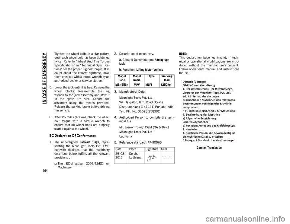
EC Declaration Of Conformance
1. The undersigned, Jaswant Singh, repre-
senting the Moonlight Tools Pvt. Ltd.,
herewith declares that the machinery
described below fulfills all the relevant
provisions of:
The EC-directive 2006/42/EC on Machinery 2. Description of machinery.
a. Generic Denomination: Pantograph
jack
b. Function: Lifting Motor Vehicle
3. Manufacturer Detail Moonlight Tools Pvt. Ltd.
Vill. Jaspalon, G.T. Road Doraha
Distt. Ludhiana (141421) Punjab (India)
Teh. PH. No. 01628 258302
4. Authorized Person to compile the tech -
nical file
Mr. Jaswant Singh DGM (QA & Dev.)
Moonlight Tools Pvt. Ltd.
Ludhiana
5. Reference standard: PF-90065 NOTE:
This declaration becomes invalid, if tech
-
nical or operational modifications are intro -
duced without the manufacture’s consent.
Follow operational manual and instructions
for use.
German Translation
Model
Code Model
Name Type Working
load
M6 (556) MPV MLF1 1250Kg
Date Place
Signature Seal
29–03–
2017 Doraha
Ludhiana
2020_JEEP_M6_UG_UK.book Page 194
Page 232 of 328
SERVICING AND MAINTENANCE
230
(Continued)
Cooling System Pressure Cap
The cap must be fully tightened to prevent
loss of engine coolant (antifreeze), and to
ensure that engine coolant (antifreeze) will
return to the radiator from the coolant expan-
sion bottle/recovery tank if so equipped.
The cap should be inspected and cleaned if
there is any accumulation of foreign material
on the sealing surfaces.
Brake System
In order to assure brake system performance,
all brake system components should be
inspected periodically. Refer to the “Mainte -nance Plan” in this section for the proper
maintenance intervals.
Brake Master Cylinder
The fluid in the master cylinder should be
checked when performing under hood
services or immediately if the “Brake
Warning Light” is illuminated.
Be sure to clean the top of the master
cylinder area before removing the cap. If
necessary, add fluid to bring the fluid level
up to the requirements described on the
brake fluid reservoir. With disc brakes, fluid
level can be expected to fall as the brake
pads wear. Brake fluid level should be
checked when pads are replaced. However,
low fluid level may be caused by a leak and
a checkup may be needed.
Use only manufacturer's recommended
brake fluid. Refer to “Fluids And Lubricants”
in “Technical Specifications” for further
information.
WARNING!
Do not open hot engine cooling system.
Never add engine coolant (antifreeze)
when the engine is overheated. Do not
loosen or remove the cap to cool an over
-
heated engine. Heat causes pressure to
build up in the cooling system. To
prevent scalding or injury, do not remove
the pressure cap while the system is hot
or under pressure.
Do not use a pressure cap other than the
one specified for your vehicle. Personal
injury or engine damage may result.
WARNING!
Riding the brakes can lead to brake failure
and possibly a collision. Driving with your
foot resting or riding on the brake pedal
can result in abnormally high brake
temperatures, excessive lining wear, and
possible brake damage. You would not
have your full braking capacity in an
emergency. WARNING!
Use only manufacturer's recommended
brake fluid. Refer to “Fluids And Lubri -
cants” in “Technical Specifications” for
further information. Using the wrong
type of brake fluid can severely damage
your brake system and/or impair its
performance. The proper type of brake
fluid for your vehicle is also identified on
the original factory installed hydraulic
master cylinder reservoir.
To avoid contamination from foreign
matter or moisture, use only new brake
fluid or fluid that has been in a tightly
closed container. Keep the master
cylinder reservoir cap secured at all
times. Brake fluid in a open container
absorbs moisture from the air resulting
in a lower boiling point. This may cause
it to boil unexpectedly during hard or
prolonged braking, resulting in sudden
brake failure. This could result in a colli -
sion.
2020_JEEP_M6_UG_UK.book Page 230
Page 233 of 328
231
Manual Transmission — If Equipped
Fluid Level Check
Check the fluid level by removing the fill
plug. The fluid level should be between the
bottom of the fill hole and a point not more
than 3/16 inch (4.7 mm) below the bottom
of the hole.
Add fluid, if necessary, to maintain the
proper level.
Please see your authorized dealer for service.
Automatic Transmission
Selection Of Lubricant
It is important to use the proper transmission
fluid to ensure optimum transmission perfor-
mance and life. Use only the manufacturer's
specified transmission fluid. Refer to “Fluids
And Lubricants” in “Technical Specifica -
tions” for fluid specifications. It is important
to maintain the transmission fluid at the
correct level using the recommended fluid.
NOTE:
No chemical flushes should be used in any
transmission; only the approved lubricant
should be used.
Special Additives
The manufacturer strongly recommends
against using any special additives in the transmission. Automatic Transmission Fluid
(ATF) is an engineered product and its
performance may be impaired by supple
-
mental additives. Therefore, do not add any
fluid additives to the transmission. Avoid
using transmission sealers as they may
adversely affect seals.
Fluid Level Check
The fluid level is preset at the factory and
does not require adjustment under normal
operating conditions. Routine fluid level
checks are not required; therefore the trans -
mission has no dipstick. An authorized
dealer can check your transmission fluid
level using special service tools. If you notice
fluid leakage or transmission malfunction,
visit an authorized dealer immediately to
have the transmission fluid level checked.
Operating the vehicle with an improper fluid
level can cause severe transmission damage.
Overfilling the brake fluid reservoir can
result in spilling brake fluid on hot
engine parts, causing the brake fluid to
catch fire. Brake fluid can also damage
painted and vinyl surfaces, care should
be taken to avoid its contact with these
surfaces.
Do not allow petroleum based fluid to
contaminate the brake fluid. Brake seal
components could be damaged, causing
partial or complete brake failure. This
could result in a collision.
WARNING! (Continued)
CAUTION!
Using a transmission fluid other than the
manufacturer’s recommended fluid may
cause deterioration in transmission shift
quality and/or torque converter shudder.
Refer to “Fluids And Lubricants” in
“Technical Specifications” for fluid
specifications.
CAUTION!
Do not use chemical flushes in your
transmission as the chemicals can damage
your transmission components. Such
damage is not covered by the New Vehicle
Limited Warranty.
2020_JEEP_M6_UG_UK.book Page 231
Page 246 of 328
244
TECHNICAL SPECIFICATIONS
IDENTIFICATION DATA
Vehicle Identification Number
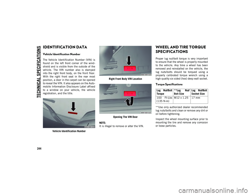
The Vehicle Identification Number (VIN) is
found on the left front corner of the wind-
shield and is visible from the outside of the
vehicle. The VIN number also is stamped
into the right front body, on the front floor.
With the right front seat in the rear most
position, a door in the carpet can be opened
to reveal the VIN. It also appears on the Auto -
mobile Information Disclosure Label affixed
to a window on your vehicle, the vehicle
registration, and the title.
Vehicle Identification Number Right Front Body VIN Location
Opening The VIN Door
NOTE:
It is illegal to remove or alter the VIN.
WHEEL AND TIRE TORQUE
SPECIFICATIONS
Proper lug nut/bolt torque is very important
to ensure that the wheel is properly mounted
to the vehicle. Any time a wheel has been
removed and reinstalled on the vehicle, the
lug nuts/bolts should be torqued using a
properly calibrated torque wrench using a
high quality six sided (hex) deep wall socket.
Torque Specifications
**Use only authorized dealer recommended
lug nuts/bolts and clean or remove any dirt or
oil before tightening.
Inspect the wheel mounting surface prior to
mounting the tire and remove any corrosion
or loose particles.
Lug Nut/Bolt
Torque **Lug Nut/
Bolt SizeLug Nut/Bolt
Socket Size
100 Ft-Lbs
(135 N·m) M12 x 1.25 17 mm
2020_JEEP_M6_UG_UK.book Page 244
Page 248 of 328
TECHNICAL SPECIFICATIONS
246
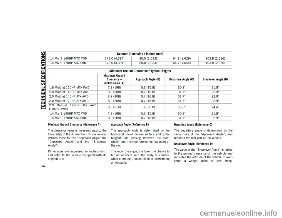
Minimum Ground Clearance (Reference A)
The clearance value is measured next to the
lower edge of the differential. This value also
defines those for the “Approach Angle” the
“Departure Angle” and the “Breakover
Angle”.
Dimensions are expressed in inches (mm)
and refer to the vehicle equipped with its
original tires.Approach Angle (Reference B)
The approach angle is determined by the
horizontal line of the road surface, and by the
tangent line passing between the front
wheel, and the most projecting low point of
the car.
The wider the angle, the lower the chance to
hit an obstacle with the body or chassis,
when climbing a steep slope or overcoming
an obstacle.Departure Angle (Reference C)
The departure angle is determined by the
same lines of the “Approach Angle”, and
refers to the rear part of the vehicle.
Breakover Angle (Reference D)
The value of the “Breakover Angle” is linked
to the ground clearance of the vehicle and
indicates the attitude of the vehicle to over
-
come a wedge, more or less steep,
1.4 Mair2 140HP MTX FWD
173.0 (4,394) 80.0 (2,033) 64.1 (1,629) 103.8 (2,636)
1.4 Mair2 170HP ATX AWD 173.0 (4,394) 80.0 (2,033) 64.7 (1,644) 103.8 (2,636)
Minimum Ground Clearance / Typical Angles
Maximum Ground
Clearance –
inches (mm) (A) Approach Angle (B) Departure Angle (C) Breakover Angle (D)
1.6 Multijet 120HP MTX FWD 7.8 (198)0.6 (15.8) 30.8°21.8°
2.0 Multijet 140HP MTX AWD 8.2 (208)0.7 (16.8) 31.7°22.9°
2.0 Multijet 140HP ATX AWD 8.2 (208)0.7 (16.8) 31.7°22.9°
2.0 Multijet 170HP ATX AWD 8.2 (208)0.7 (16.8) 31.7°22.9°
2.0 Multijet 170HP ATX AWD
(TRAILHAWK) 8.5 (216)
1.2 (30.0) 33.6°24.4°
1.4 Mair2 140HP MTX FWD 7.8 (198)0.6 (15.8) 30.8°21.8°
1.4 Mair2 170HP ATX AWD 8.2 (208)0.7 (16.8) 31.7°22.9°
Contour Dimension / inches (mm)
2020_JEEP_M6_UG_UK.book Page 246
Page 250 of 328
TECHNICAL SPECIFICATIONS
248
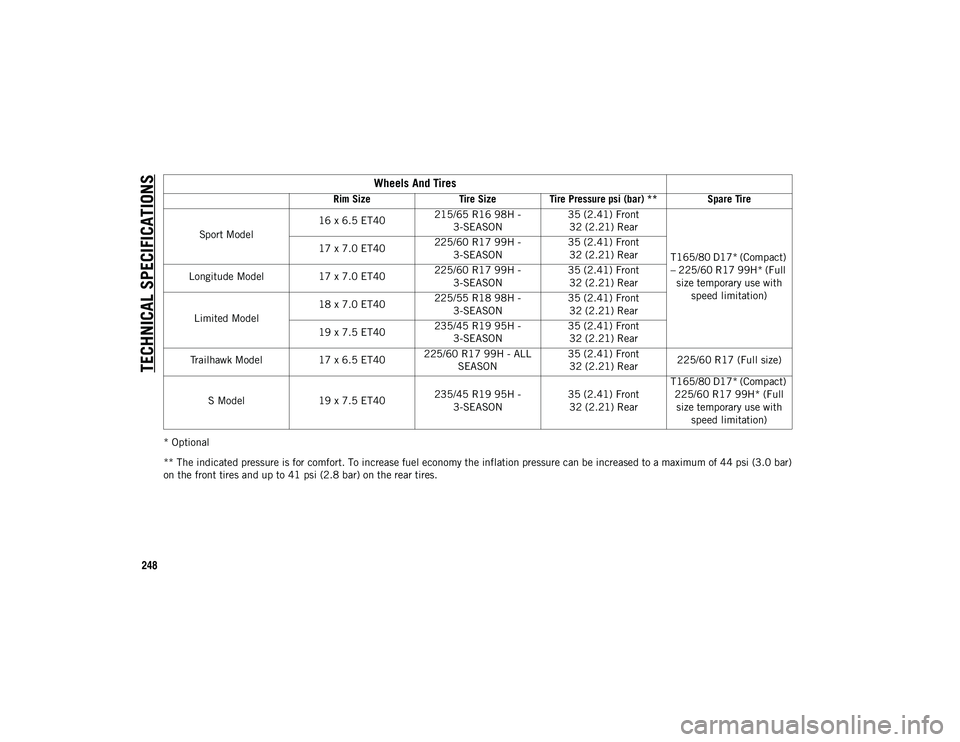
* Optional
** The indicated pressure is for comfort. To increase fuel economy the inflation pressure can be increased to a maximum of 44 psi (3.0 bar)
on the front tires and up to 41 psi (2.8 bar) on the rear tires.
Wheels And Tires
Rim SizeTire SizeTire Pressure psi (bar) ** Spare Tire
Sport Model 16 x 6.5 ET40
215/65 R16 98H -
3-SEASON 35 (2.41) Front
32 (2.21) Rear
T165/80 D17* (Compact)
– 225/60 R17 99H* (Full size temporary use with speed limitation)
17 x 7.0 ET40
225/60 R17 99H -
3-SEASON 35 (2.41) Front
32 (2.21) Rear
Longitude Model 17 x 7.0 ET40225/60 R17 99H -
3-SEASON 35 (2.41) Front
32 (2.21) Rear
Limited Model 18 x 7.0 ET40
225/55 R18 98H -
3-SEASON 35 (2.41) Front
32 (2.21) Rear
19 x 7.5 ET40 235/45 R19 95H -
3-SEASON 35 (2.41) Front
32 (2.21) Rear
Trailhawk Model 17 x 6.5 ET40225/60 R17 99H - ALL
SEASON 35 (2.41) Front
32 (2.21) Rear 225/60 R17 (Full size)
S Model 19 x 7.5 ET40 235/45 R19 95H -
3-SEASON 35 (2.41) Front
32 (2.21) Rear T165/80 D17* (Compact)
225/60 R17 99H* (Full size temporary use with speed limitation)
2020_JEEP_M6_UG_UK.book Page 248