warning light JEEP COMPASS 2023 Service Manual
[x] Cancel search | Manufacturer: JEEP, Model Year: 2023, Model line: COMPASS, Model: JEEP COMPASS 2023Pages: 344, PDF Size: 18.8 MB
Page 124 of 344
122STARTING AND OPERATING
To Resume
If there is a set speed in memory, push the RES
(resume) button and remove your foot from the
accelerator pedal. The instrument cluster display
will show the last set speed.
Resume can be used at any speed above 20 mph
(32 km/h) when only Fixed Speed Cruise Control is
being used.
Resume can be used at any speed above 0 mph
(0 km/h) when ACC is active.
NOTE:
If your vehicle is at standstill longer than two
seconds, the driver will either have to push the
RES (resume) button, or apply the accelerator
pedal to reengage the Adaptive Cruise Control
(ACC) to the existing set speed
ACC cannot be resumed if there is a stationary
vehicle in front of your vehicle in close proximity.
To Vary The Speed Setting
To Increase Or Decrease The Set Speed
After setting a speed, you can increase the set
speed by pushing the SET (+) button, or decrease
speed by pushing the SET (-) button.
U.S. Speed (mph)
Pushing the SET (+) , or SET (-) button once will
result in a 1 mph speed adjustment. Each
subsequent tap of the button results in an
adjustment of 1 mph.
If the button is continually pushed, the set
speed will continue to adjust in 5 mph incre -
ments until the button is released. The new set
speed is reflected in the instrument cluster
display.
Metric Speed (km/h)
Pushing the SET (+) , or SET (-) button once will
result in a 1 km/h speed adjustment. Each
subsequent tap of the button results in an
adjustment of 1 km/h.
If the button is continually pushed, the set
speed will continue to adjust in 10 km/h incre -
ments until the button is released. The new set
speed is reflected in the instrument cluster
display.
NOTE:When you override and push the SET (+) button or
SET (-) button, the new set speed will be the current
speed of the vehicle.
When ACC Is Active
When you use the SET (-) button to decelerate, if
the engine’s braking power does not slow the
vehicle sufficiently to reach the set speed, the
brake system will automatically slow the
vehicle.
The ACC system decelerates the vehicle to a full
stop when following the vehicle in front. If your
vehicle follows the vehicle in front to a standstill,
after two seconds the driver will either have to
push the RES (resume) button, or apply the
accelerator pedal to reengage the ACC to the
existing set speed.
The ACC system maintains set speed when
driving uphill and downhill. However, a slight
speed change on moderate hills is normal. In
addition, downshifting may occur while climbing
uphill or descending downhill. This is normal
operation and necessary to maintain set speed.
When driving uphill and downhill, the ACC
system will cancel if the braking temperature
exceeds normal range (overheated).
WARNING!
The Resume function should only be used if
traffic and road conditions permit. Resuming a
set speed that is too high or too low for
prevailing traffic and road conditions could
cause the vehicle to accelerate or decelerate too
sharply for safe operation. Failure to follow these
warnings can result in a collision and death or
serious personal injury.
22_MP_OM_EN_USC_t.book Page 122
Page 125 of 344
STARTING AND OPERATING123
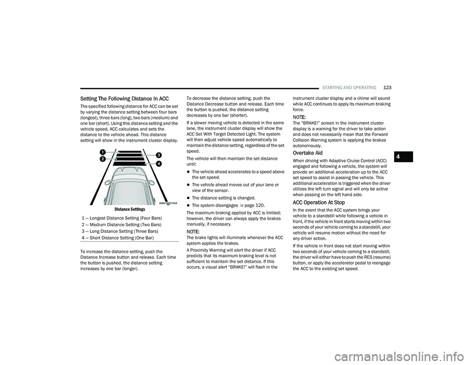
Setting The Following Distance In ACC
The specified following distance for ACC can be set
by varying the distance setting between four bars
(longest), three bars (long), two bars (medium) and
one bar (short). Using this distance setting and the
vehicle speed, ACC calculates and sets the
distance to the vehicle ahead. This distance
setting will show in the instrument cluster display.
Distance Settings
To increase the distance setting, push the
Distance Increase button and release. Each time
the button is pushed, the distance setting
increases by one bar (longer). To decrease the distance setting, push the
Distance Decrease button and release. Each time
the button is pushed, the distance setting
decreases by one bar (shorter).
If a slower moving vehicle is detected in the same
lane, the instrument cluster display will show the
ACC Set With Target Detected Light. The system
will then adjust vehicle speed automatically to
maintain the distance setting, regardless of the set
speed.
The vehicle will then maintain the set distance
until:
The vehicle ahead accelerates to a speed above
the set speed.
The vehicle ahead moves out of your lane or
view of the sensor.
The distance setting is changed.
The system disengages Ú
page 120.
The maximum braking applied by ACC is limited;
however, the driver can always apply the brakes
manually, if necessary.
NOTE:The brake lights will illuminate whenever the ACC
system applies the brakes.
A Proximity Warning will alert the driver if ACC
predicts that its maximum braking level is not
sufficient to maintain the set distance. If this
occurs, a visual alert “BRAKE!” will flash in the instrument cluster display and a chime will sound
while ACC continues to apply its maximum braking
force.
NOTE:The “BRAKE!” screen in the instrument cluster
display is a warning for the driver to take action
and does not necessarily mean that the Forward
Collision Warning system is applying the brakes
autonomously.
Overtake Aid
When driving with Adaptive Cruise Control (ACC)
engaged and following a vehicle, the system will
provide an additional acceleration up to the ACC
set speed to assist in passing the vehicle. This
additional acceleration is triggered when the driver
utilizes the left turn signal and will only be active
when passing on the left hand side.
ACC Operation At Stop
In the event that the ACC system brings your
vehicle to a standstill while following a vehicle in
front, if the vehicle in front starts moving within two
seconds of your vehicle coming to a standstill, your
vehicle will resume motion without the need for
any driver action.
If the vehicle in front does not start moving within
two seconds of your vehicle coming to a standstill,
the driver will either have to push the RES (resume)
button, or apply the accelerator pedal to reengage
the ACC to the existing set speed.
1 — Longest Distance Setting (Four Bars)
2 — Medium Distance Setting (Two Bars)
3 — Long Distance Setting (Three Bars)
4 — Short Distance Setting (One Bar)
4
22_MP_OM_EN_USC_t.book Page 123
Page 133 of 344
STARTING AND OPERATING131
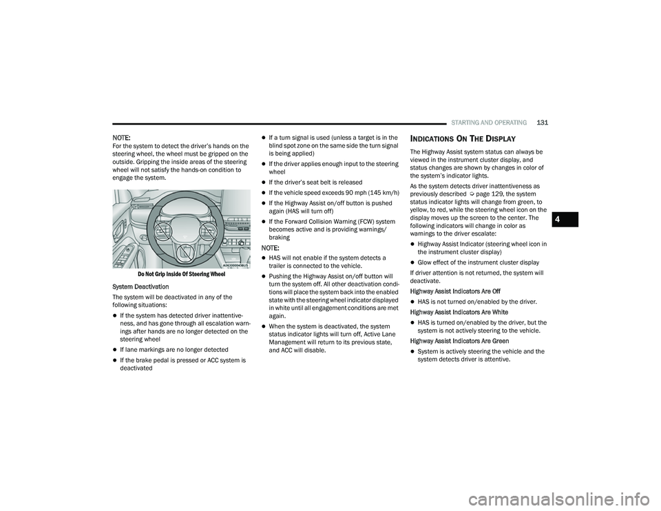
NOTE:For the system to detect the driver’s hands on the
steering wheel, the wheel must be gripped on the
outside. Gripping the inside areas of the steering
wheel will not satisfy the hands-on condition to
engage the system.
Do Not Grip Inside Of Steering Wheel
System Deactivation
The system will be deactivated in any of the
following situations:
If the system has detected driver inattentive -
ness, and has gone through all escalation warn -
ings after hands are no longer detected on the
steering wheel
If lane markings are no longer detected
If the brake pedal is pressed or ACC system is
deactivated
If a turn signal is used (unless a target is in the
blind spot zone on the same side the turn signal
is being applied)
If the driver applies enough input to the steering
wheel
If the driver’s seat belt is released
If the vehicle speed exceeds 90 mph (145 km/h)
If the Highway Assist on/off button is pushed
again (HAS will turn off)
If the Forward Collision Warning (FCW) system
becomes active and is providing warnings/
braking
NOTE:
HAS will not enable if the system detects a
trailer is connected to the vehicle.
Pushing the Highway Assist on/off button will
turn the system off. All other deactivation condi -
tions will place the system back into the enabled
state with the steering wheel indicator displayed
in white until all engagement conditions are met
again.
When the system is deactivated, the system
status indicator lights will turn off, Active Lane
Management will return to its previous state,
and ACC will disable.
INDICATIONS ON THE DISPLAY
The Highway Assist system status can always be
viewed in the instrument cluster display, and
status changes are shown by changes in color of
the system’s indicator lights.
As the system detects driver inattentiveness as
previously described Ú page 129, the system
status indicator lights will change from green, to
yellow, to red, while the steering wheel icon on the
display moves up the screen to the center. The
following indicators will change in color as
warnings to the driver escalate:
Highway Assist Indicator (steering wheel icon in
the instrument cluster display)
Glow effect of the instrument cluster display
If driver attention is not returned, the system will
deactivate.
Highway Assist Indicators Are Off
HAS is not turned on/enabled by the driver.
Highway Assist Indicators Are White
HAS is turned on/enabled by the driver, but the
system is not actively steering to the vehicle.
Highway Assist Indicators Are Green
System is actively steering the vehicle and the
system detects driver is attentive.
4
22_MP_OM_EN_USC_t.book Page 131
Page 134 of 344

132STARTING AND OPERATING
(Continued)
Highway Assist Indicators Are Yellow
Driver inattentiveness has been detected,
warning the driver to place hands on the
steering wheel.
Highway Assist Indicators Are Red
Driver inattentiveness is still being detected,
warning the driver to place hands on the
steering wheel.
NOTE:The driver MUST replace hands on the steering
wheel and take control of the vehicle when the
system is deactivated.
Highway Assist Cancelled Message
SYSTEM STATUS
Along with changes in the system’s indicator lights
(green, yellow, and red), the system can also issue
a steering wheel vibration to accompany these
warnings. The vibration warning (if enabled) will
occur if the vehicle crosses a lane marker, for
example, when driving on a tight curve. This
feature can be turned on or off within the Uconnect
system Ú page 165.
SYSTEM OPERATION/LIMITATIONS
The Highway Assist system DOES NOT:
Warn or prevent collisions with other vehicles
Steer your vehicle around stopped vehicles,
slower vehicles, construction equipment,
pedestrians, or animals
Respond to traffic lights or stop signs
Merge onto highways or exit off-ramps
Change lanes or turn
React to cross traffic
NOTE:Adaptive Cruise Control (ACC) is a core component
of the Highway Assist system. For ACC system
limitations Úpage 118.
WARNING!
Highway Assist is an SAE Level 2 Driver Assist
feature, requiring driver attention at all times.
To prevent serious injury or death:
Always remain alert and be ready to take
control of the vehicle in the event that the
Highway Assist system disables.
Always keep your hands on the steering wheel
when the Highway Assist system is activated.
Do not use a hand-held device when the
Highway Assist system is engaged.
Maintain a safe distance from other vehicles
and pay attention to traffic conditions.
Do not place any objects on the steering wheel
(e.g. steering wheel covers) which could inter -
fere with the hand detection sensors.
WARNING!
22_MP_OM_EN_USC_t.book Page 132
Page 155 of 344
STARTING AND OPERATING153
4. Keep the nozzle in the filler for five seconds after nozzle clicks to allow fuel to drain from
the nozzle.
5. Remove the fuel nozzle and close the fuel door.
VEHICLE LOADING
CERTIFICATION LABEL
As required by National Highway Traffic Safety
Administration regulations, your vehicle has a
certification label affixed to the driver's side door or
pillar. This label contains the month and year of
manufacture, Gross Vehicle Weight Rating
(GVWR), front and rear Gross Axle Weight Rating
(GAWR), and Vehicle Identification Number (VIN).
A Month-Day-Hour (MDH) number is included on
this label and indicates the Month, Day and Hour of
manufacture. The bar code that appears on the
bottom of the label is your VIN.
Gross Vehicle Weight Rating (GVWR)
The GVWR is the total permissible weight of your
vehicle including driver, passengers, vehicle,
options and cargo. The label also specifies
maximum capacities of front and rear Gross Axle
Weight Rating (GAWR). Total load must be limited so
GVWR and front and rear GAWR are not exceeded.
Payload
The payload of a vehicle is defined as the allowable
load weight a truck can carry, including the weight
of the driver, all passengers, options and cargo.
Gross Axle Weight Rating (GAWR)
The GAWR is the maximum permissible load on the
front and rear axles. The load must be distributed
in the cargo area so that the GAWR of each axle is
not exceeded.
Each axle GAWR is determined by the components
in the system with the lowest load carrying capacity
(axle, springs, tires or wheels). Heavier axles or suspension components sometimes specified by
purchasers for increased durability does not
necessarily increase the vehicle's GVWR.
Tire Size
The tire size on the Vehicle Certification Label
represents the actual tire size on your vehicle.
Replacement tires must be equal to the load
capacity of this tire size.
Rim Size
This is the rim size that is appropriate for the tire
size listed.
Inflation Pressure
This is the cold tire inflation pressure for your
vehicle for all loading conditions up to full GAWR.
Curb Weight
The curb weight of a vehicle is defined as the total
weight of the vehicle with all fluids, including
vehicle fuel, at full capacity conditions, and with no
occupants or cargo loaded into the vehicle. The
front and rear curb weight values are determined
by weighing your vehicle on a commercial scale
before any occupants or cargo are added.
Loading
The actual total weight and the weight of the front
and rear of your vehicle at the ground can best be
determined by weighing it when it is loaded and
ready for operation.
WARNING!
Never have any smoking materials lit in or
near the vehicle when the fuel door is open or
the tank is being filled.
Never add fuel when the engine is running.
This is in violation of most state and federal
fire regulations and may cause the Malfunc
-
tion Indicator Light to turn on.
A fire may result if fuel is pumped into a
portable container that is inside of a vehicle.
You could be burned. Always place fuel
containers on the ground while filling.
4
22_MP_OM_EN_USC_t.book Page 153
Page 160 of 344
158STARTING AND OPERATING
Towing Requirements — Trailer Lights And
Wiring
Whenever you pull a trailer, regardless of the trailer
size, stoplights and turn signals on the trailer are
required for motoring safety.
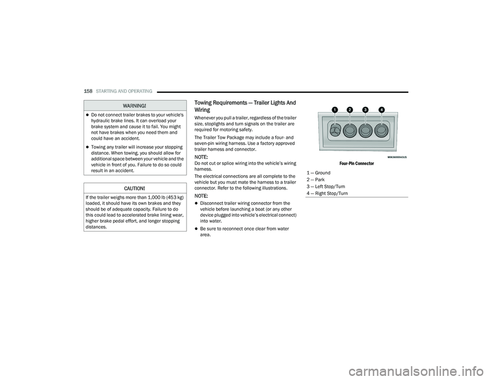
The Trailer Tow Package may include a four- and
seven-pin wiring harness. Use a factory approved
trailer harness and connector.
NOTE:Do not cut or splice wiring into the vehicle’s wiring
harness.
The electrical connections are all complete to the
vehicle but you must mate the harness to a trailer
connector. Refer to the following illustrations.
NOTE:
Disconnect trailer wiring connector from the
vehicle before launching a boat (or any other
device plugged into vehicle’s electrical connect)
into water.
Be sure to reconnect once clear from water
area.
Four-Pin Connector
WARNING!
Do not connect trailer brakes to your vehicle's
hydraulic brake lines. It can overload your
brake system and cause it to fail. You might
not have brakes when you need them and
could have an accident.
Towing any trailer will increase your stopping
distance. When towing, you should allow for
additional space between your vehicle and the
vehicle in front of you. Failure to do so could
result in an accident.
CAUTION!
If the trailer weighs more than 1,000 lb (453 kg)
loaded, it should have its own brakes and they
should be of adequate capacity. Failure to do
this could lead to accelerated brake lining wear,
higher brake pedal effort, and longer stopping
distances.
1 — Ground
2 — Park
3 — Left Stop/Turn
4 — Right Stop/Turn
22_MP_OM_EN_USC_t.book Page 158
Page 164 of 344
162STARTING AND OPERATING
Flowing Water
If the water is swift flowing and rising (as in storm
run-off) avoid crossing until the water level recedes
and/or the flow rate is reduced. If you must cross
flowing-water, avoid depths in excess of 9 inches
(22 cm). The flowing water can erode the
streambed causing your vehicle to sink into deeper
water. Determine exit point(s) that are downstream
of your entry point to allow for drifting.
Standing Water
Avoid driving in standing water deeper than
16 inches (40.5 cm), and reduce speed
appropriately to minimize wave effects. Maximum
speed in 16 inches (40.5 cm) of water is less than
5 mph (8 km/h).
(Trailhawk only): Avoid driving in standing water
deeper than 19 inches (48 cm), and reduce speed
appropriately to minimize wave effects. Maximum
speed in 19 inches (48 cm) of water is less than
5 mph (8 km/h).
Maintenance
After driving through deep water, inspect your
vehicle fluids and lubricants (engine, transmission,
Power Transfer Unit, and Rear Drive Module) to
ensure they have not been contaminated.
Contaminated fluids and lubricants (milky, foamy
in appearance) should be flushed/changed as
soon as possible to prevent component damage.
Driving In Snow, Mud And Sand
In heavy snow, when pulling a load, or for
additional control at slower speeds, shift the
transmission to a low gear and shift the 4WD
system to the appropriate terrain mode, using
4WD LOW if necessary Úpage 112. Do not shift to
a lower gear than necessary to maintain headway.
Over-revving the engine can spin the wheels and
traction will be lost.
Avoid abrupt downshifts on icy or slippery roads
because engine braking may cause skidding and
loss of control.
Hill Climbing
NOTE:Before attempting to climb a hill, determine the
conditions at the crest and/or on the other side.
Before climbing a steep hill, shift the transmission
to a lower gear and shift the 4WD System to 4WD
LOW. Use FIRST gear and 4WD LOW for very steep
hills.
NOTE:Brakes should be applied at increased slippage,
but before coming to a stop to avoid digging into
the loose surface and rendering the operator of the
vehicle stuck/immobile. If you stall or begin to lose headway
while climbing
a steep hill, allow your vehicle to come to a stop
and immediately apply the brakes. Once stopped,
shift to REVERSE. Back slowly down the hill
allowing the compression braking of the engine to
help regulate your speed. If the brakes are
required to control vehicle speed, apply them
lightly and avoid locking or skidding the tires.
NOTE:Remember, never drive diagonally across a hill -
drive straight up or down.
If the wheels start to slip as you approach the crest
of a hill, ease off the accelerator and maintain
headway by turning the front wheels slowly left and
right. This may provide a fresh “bite” into the
surface and may provide traction to complete the
climb.
WARNING!
If the engine stalls or you lose headway or
cannot make it to the top of a steep hill or grade,
never attempt to turn around. To do so may
result in tipping and rolling the vehicle. Always
back straight down a hill in REVERSE gear
carefully. Never back down a hill in NEUTRAL
using only the brake.
22_MP_OM_EN_USC_t.book Page 162
Page 174 of 344
172MULTIMEDIA
Rear ParkSense Braking Assist This setting will provide braking assistance if the Rear ParkSense system
senses a collision with an object.
Active ParkSense Mode This setting will control Active ParkSense functionality between fully
autonomous parking and semi-autonomous parking. The available options
are “Full Auto” and “Steering Only”.
Active ParkSense Proximity Chime This setting will turn the Active ParkSense Proximity Chimes on or off. This
setting in only available when Active ParkSense Mode is set to “Full Auto”.
Blind Spot Alert This setting will change the type of alert provided when an object is detected
in the vehicle’s blind spot. The “Off” setting will turn off Blind Spot Alert. The
“Lights” setting will activate the Blind Spot Alert lights on the outside mirrors.
The “Lights & Chime” setting will activate both the lights on the outside
mirrors and an audible chime.
Traffic Sign Assist This setting will turn Traffic Sign Assist on or off.
Traffic Sign Assist Warning This setting will allow you to set the warning type related to the traffic sign.
The available options are “Off”, “Visual”, and “Visual + Chime”.
New Speed Zone Indication This setting will allow you to set if the system will warn you that the speed limit
has changed in an area. The available options are “Off”, “Visual”, and
“Visual + Chime”.
Drowsy Driver Alert This setting will monitor the driver’s driving habits and warn you of any
changes, indicating that the driver may be drowsy. The available options are
“On” and “Off”.
Highway Assist Steering Wheel Vibration This setting will vibrate the steering wheel when a lane departure is detected.
The available options are “On” and “Off”.
Setting Name
Description
22_MP_OM_EN_USC_t.book Page 172
Page 189 of 344
187
(Continued)
SAFETY
SAFETY FEATURES
ANTI-LOCK BRAKE SYSTEM (ABS)
The ABS provides increased vehicle stability and
brake performance under most braking conditions.
The system automatically prevents wheel lock and
enhances vehicle control during braking.
The ABS performs a self-check cycle to ensure that
the ABS is working properly each time the vehicle
is started and driven. During this self-check, you
may hear a slight clicking sound as well as some
related motor noises.
The ABS is activated during braking when the
system detects one or more wheels are beginning
to lock. Road conditions such as ice, snow, gravel,
bumps, railroad tracks, loose debris, or panic stops
may increase the likelihood of ABS activation(s).
You also may experience the following normal
characteristics when the ABS activates:
ABS motor noise or clicking sounds (you may
continue to hear for a short time after the stop)
Brake pedal pulsations
A slight drop of the brake pedal at the end of
the stopThe ABS is designed to function with the Original
Equipment Manufacturer (OEM) tires. Modification
may result in degraded ABS performance.
Anti-Lock Brake System (ABS) Warning
Light
The yellow ABS Warning Light will turn on when the
ignition is placed in the ON/RUN mode and may
stay on for as long as four seconds.
If the ABS Warning Light remains on or comes on
while driving, it indicates that the anti-lock portion
of the brake system is not functioning and that
service is required. However, the conventional
brake system will continue to operate normally if
the ABS Warning Light is on.
If the ABS Warning Light is on, the brake system
should be serviced as soon as possible to restore
the benefits of Anti-lock Brakes. If the ABS Warning
WARNING!
The ABS contains sophisticated electronic
equipment that may be susceptible to interfer
-
ence caused by improperly installed or high
output radio transmitting equipment. This
interference can cause possible loss of
anti-lock braking capability. Installation of
such equipment should be performed by
qualified professionals.
Pumping of the Anti-Lock Brakes will diminish
their effectiveness and may lead to a collision.
Pumping makes the stopping distance longer.
Just press firmly on your brake pedal when you
need to slow down or stop.
The ABS cannot prevent the natural laws of
physics from acting on the vehicle, nor can it
increase braking or steering efficiency beyond
that afforded by the condition of the vehicle
brakes and tires or the traction afforded.
The ABS cannot prevent collisions, including
those resulting from excessive speed in turns,
following another vehicle too closely, or hydro -
planing.
The capabilities of an ABS equipped vehicle
must never be exploited in a reckless or
dangerous manner that could jeopardize the
user’s safety or the safety of others.
WARNING!
6
22_MP_OM_EN_USC_t.book Page 187
Page 190 of 344
188SAFETY
Light does not come on when the ignition is placed
in the ON/RUN mode, have the light repaired as
soon as possible.
ELECTRONIC BRAKE CONTROL (EBC)
S
YSTEM
Your vehicle is equipped with an advanced
Electronic Brake Control (EBC) system. This system
includes Anti-Lock Brake System (ABS), Brake Assist
System (BAS), Electronic Brake Force Distribution
(EBD), Electronic Roll Mitigation (ERM), Electronic
Stability Control (ESC), Hill Start Assist (HSA), and
Traction Control System (TCS). These systems work
together to enhance both vehicle stability and
control in various driving conditions.
Your vehicle may also be equipped with Dynamic
Steering Torque (DST), Hill Descent Control (HDC),
Rain Brake Support (RBS), Ready Alert Braking
(RAB), and Trailer Sway Control (TSC).
Brake Assist System (BAS)
The BAS is designed to optimize the vehicle’s
braking capability during emergency braking
maneuvers. The system detects an emergency
braking situation by sensing the rate and amount
of brake application and then applies optimum
pressure to the brakes. This can help reduce
braking distances. The BAS complements the
Anti-Lock Brake System (ABS). Applying the brakes
very quickly results in the best BAS assistance. To receive the benefit of the system, you must
apply continuous braking pressure during the
stopping sequence (do not “pump” the brakes). Do
not reduce brake pedal pressure unless braking is
no longer desired. Once the brake pedal is
released, the BAS is deactivated.
Brake System Warning Light
The red Brake System Warning Light will turn on
when the ignition is placed in the ON/RUN mode
and may stay on for as long as four seconds.
If the Brake System Warning Light remains on or
comes on while driving, it indicates that the brake
system is not functioning properly and that
immediate service is required. If the Brake System
Warning Light does not come on when the ignition
is placed in the ON/RUN mode, have the light
repaired as soon as possible.
Dynamic Steering Torque (DST)
DST is a feature of the Electronic Stability Control
(ESC) and Electric Power Steering (EPS) modules
that provides torque at the steering wheel for
certain driving conditions in which the ESC module
is detecting vehicle instability. The torque that the
steering wheel receives is only meant to help the
driver realize optimal steering behavior in order to
reach/maintain vehicle stability. The only
notification the driver receives that the feature is
active is the torque applied to the steering wheel.
NOTE:The DST feature is only meant to help the driver
realize the correct course of action through small
torques on the steering wheel, which means the
effectiveness of the DST feature is highly
dependent on the driver’s sensitivity and overall
reaction to the applied torque. It is very important
to realize that this feature will not steer the vehicle,
meaning the driver is still responsible for steering
the vehicle.
Electronic Brake Force Distribution (EBD)
EBD manages the distribution of the braking
torque between the front and rear axles by limiting
braking pressure to the rear axle. This is done to
prevent overslip of the rear wheels to avoid vehicle
instability, and to prevent the rear axle from
entering ABS before the front axle.
WARNING!
The Brake Assist System (BAS) cannot prevent the
natural laws of physics from acting on the vehicle,
nor can it increase the traction afforded by
prevailing road conditions. BAS cannot prevent
collisions, including those resulting from excessive
speed in turns, driving on very slippery surfaces, or
hydroplaning. The capabilities of a BAS-equipped
vehicle must never be exploited in a reckless or
dangerous manner, which could jeopardize the
user's safety or the safety of others.
22_MP_OM_EN_USC_t.book Page 188