stop start JEEP COMPASS 2023 Repair Manual
[x] Cancel search | Manufacturer: JEEP, Model Year: 2023, Model line: COMPASS, Model: JEEP COMPASS 2023Pages: 344, PDF Size: 18.8 MB
Page 226 of 344

224SAFETY
Enhanced Accident Response System
In the event of an impact, if the communication
network remains intact, and the power remains
intact, depending on the nature of the event, the
Occupant Restraint Controller (ORC) will determine
whether to have the Enhanced Accident Response
System perform the following functions:
Cut off fuel to the engine (if equipped)
Cut off battery power to the electric motor
(if equipped)
Flash hazard lights as long as the battery has
power
Turn on the interior lights, which remain on as
long as the battery has power or for 15 minutes
from the intervention of the Enhanced Accident
Response System
Unlock the power door locks Your vehicle may also be designed to perform any
of these other functions in response to the
Enhanced Accident Response System:
Turn off the Fuel Filter Heater, Turn off the HVAC
Blower Motor, Close the HVAC Circulation Door
Cut off battery power to the:
Engine
Electric Motor (if equipped)
Electric power steering
Brake booster
Electric park brake
Automatic transmission gear selector
Horn
Front wiper
Headlamp washer pump (if equipped)
NOTE:After an accident, remember to cycle the ignition to
the STOP (OFF/LOCK) position and remove the key
from the ignition switch to avoid draining the
battery. Carefully check the vehicle for fuel leaks in
the engine compartment and on the ground near
the engine compartment and fuel tank before
resetting the system and starting the engine. If
there are no fuel leaks or damage to the vehicle
electrical devices (e.g. headlights) after an
accident, reset the system by following the
procedure described below. If you have any doubt,
contact an authorized dealer.
22_MP_OM_EN_USC_t.book Page 224
Page 227 of 344

SAFETY225
Enhanced Accident Response System Reset Procedure
After the event occurs, when the system is active, a message regarding fuel cutoff is displayed. Turn the ignition switch from ignition AVV/START or MAR/ON/
RUN to ignition STOP/OFF/LOCK. Carefully check the vehicle for fuel leaks in the engine compartment and on the ground near the engine compartment and fuel
tank before resetting the system and starting the engine.
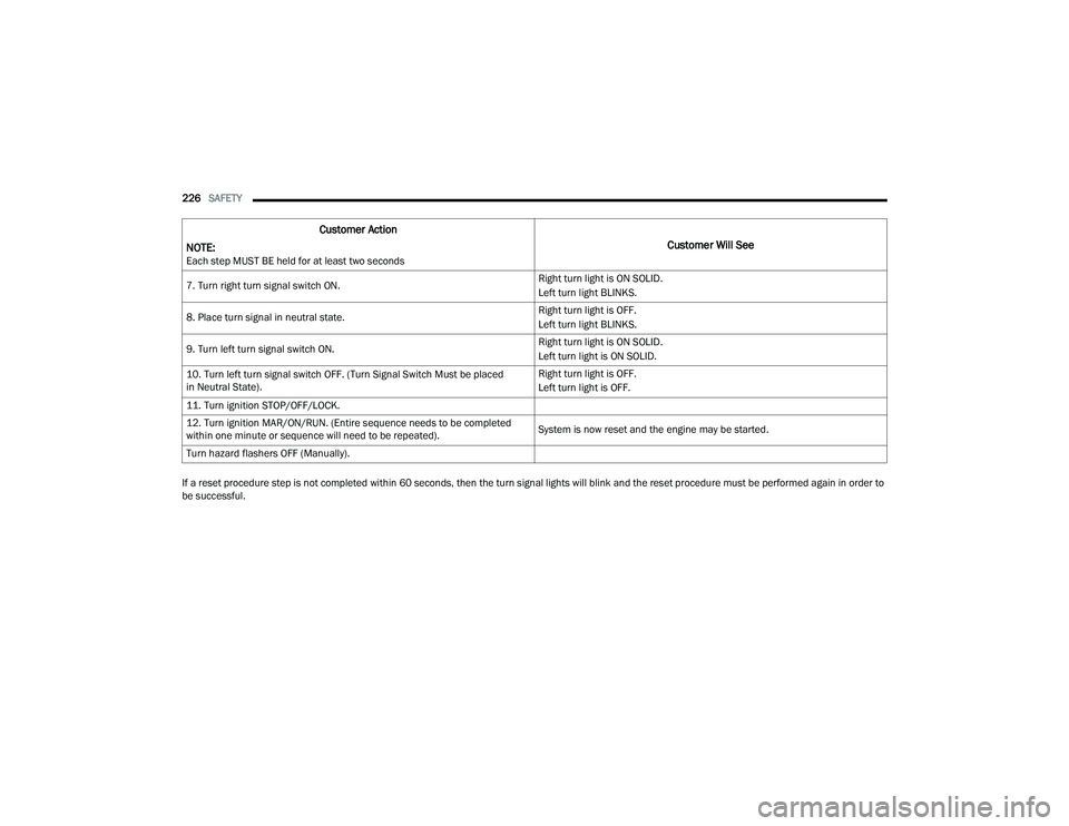
Depending on the nature of the event the left and right turn signal lights, located in the instrument panel, may both be blinking and will continue to blink. In order
to move your vehicle to the side of the road, you must follow the system reset procedure.
Customer Action
NOTE:
Each step MUST BE held for at least two seconds
Customer Will See
1. Turn ignition STOP/OFF/LOCK. (Turn Signal Switch Must be placed
in Neutral State).
2. Turn ignition MAR/ON/RUN. Right turn light BLINKS.
Left turn light is OFF.
3. Turn right turn signal switch ON. Right turn light is ON SOLID.
Left turn light BLINKS.
4. Place turn signal in neutral state. Right turn light is OFF.
Left turn light BLINKS.
5. Turn left turn signal switch ON. Right turn light BLINKS.
Left turn light is ON SOLID.
6. Place turn signal in neutral state. Right turn light BLINKS.
Left turn light is OFF.
6
22_MP_OM_EN_USC_t.book Page 225
Page 228 of 344
226SAFETY
If a reset procedure step is not completed within 60 seconds, then the turn signal lights will blink and the reset procedure must be performed again in order to
be successful. 7. Turn right turn signal switch ON.
Right turn light is ON SOLID.
Left turn light BLINKS.
8. Place turn signal in neutral state. Right turn light is OFF.
Left turn light BLINKS.
9. Turn left turn signal switch ON. Right turn light is ON SOLID.
Left turn light is ON SOLID.
10. Turn left turn signal switch OFF. (Turn Signal Switch Must be placed
in Neutral State). Right turn light is OFF.
Left turn light is OFF.
11. Turn ignition STOP/OFF/LOCK.
12. Turn ignition MAR/ON/RUN. (Entire sequence needs to be completed
within one minute or sequence will need to be repeated). System is now reset and the engine may be started.
Turn hazard flashers OFF (Manually).
Customer Action
NOTE:
Each step MUST BE held for at least two seconds
Customer Will See
22_MP_OM_EN_USC_t.book Page 226
Page 257 of 344
IN CASE OF EMERGENCY255
Sealing A Tire With Tire Service Kit
Whenever You Stop To Use Tire Service Kit:
1. Pull over to a safe location and turn on the vehicle’s Hazard Warning Flashers.
2. Verify that the valve stem (on the wheel with the deflated tire) is in a position that is near to
the ground. This will allow the Tire Service Kit
Hose to reach the valve stem and keep the Tire
Service Kit flat on the ground. This will provide
the best positioning of the kit when injecting
the sealant into the deflated tire and running
the air pump. Move the vehicle as necessary to
place the valve stem in this position before
proceeding.
3. Place the transmission in PARK and cycle the ignition in the OFF position.
4. Apply the parking brake.
Setting Up To Use Tire Service Kit:
1. Uncoil the Sealant Hose and then remove the cap from the fitting at the end of the hose.
2. Place the Tire Service Kit flat on the ground next to the deflated tire. 3. Remove the cap from the valve
stem and then screw the fitting at the
end of the Sealant Hose onto the
valve stem.
4. Uncoil the Power Plug and insert
the plug into the vehicle’s 12 Volt
power outlet.
NOTE:Do not remove foreign objects (e.g., screws or
nails) from the tire.
Injecting Tire Service Kit Sealant Into The Deflated
Tire:
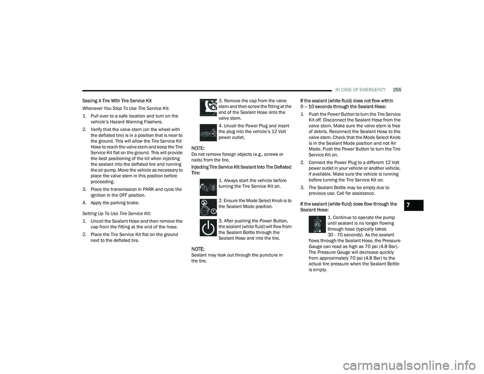
1. Always start the vehicle before
turning the Tire Service Kit on.
2. Ensure the Mode Select Knob is to
the Sealant Mode position.
3. After pushing the Power Button,
the sealant (white fluid) will flow from
the Sealant Bottle through the
Sealant Hose and into the tire.
NOTE:Sealant may leak out through the puncture in
the tire. If the sealant (white fluid) does not flow within
0 – 10 seconds through the Sealant Hose:
1. Push the Power Button to turn the Tire Service
Kit off. Disconnect the Sealant Hose from the
valve stem. Make sure the valve stem is free
of debris. Reconnect the Sealant Hose to the
valve stem. Check that the Mode Select Knob
is in the Sealant Mode position and not Air
Mode. Push the Power Button to turn the Tire
Service Kit on.
2. Connect the Power Plug to a different 12 Volt power outlet in your vehicle or another vehicle,
if available. Make sure the vehicle is running
before turning the Tire Service Kit on.
3. The Sealant Bottle may be empty due to previous use. Call for assistance.
If the sealant (white fluid) does flow through the
Sealant Hose:
1. Continue to operate the pump
until sealant is no longer flowing
through hose (typically takes
30 - 70 seconds). As the sealant
flows through the Sealant Hose, the Pressure
Gauge can read as high as 70 psi (4.8 Bar).
The Pressure Gauge will decrease quickly
from approximately 70 psi (4.8 Bar) to the
actual tire pressure when the Sealant Bottle
is empty.
7
22_MP_OM_EN_USC_t.book Page 255
Page 281 of 344
SERVICING AND MAINTENANCE279
(Continued)
(Continued)
In addition, have the exhaust system inspected
each time the vehicle is raised for lubrication or oil
change. Replace as required.
Under normal operating conditions, the catalytic
converter will not require maintenance. However, it
is important to keep the engine properly tuned to
ensure proper catalyst operation and prevent
possible catalyst damage.
NOTE:Intentional tampering with emissions control
systems can result in civil penalties being
assessed against you.
In unusual situations involving grossly
malfunctioning engine operation, a scorching odor
may suggest severe and abnormal catalyst
overheating. If this occurs, stop the vehicle, turn off
the engine and allow it to cool. Service, including a
tune-up to manufacturer specifications, should be
obtained immediately.To minimize the possibility of catalytic converter
damage:
Do not interrupt the ignition when the transmis
-
sion is in gear and the vehicle is in motion.
Do not try to start the vehicle by pushing or
towing the vehicle.
Do not idle the engine with any ignition compo -
nents disconnected or removed, such as when
diagnostic testing, or for prolonged periods
during very rough idle or malfunctioning oper -
ating conditions.
COOLING SYSTEM
WARNING!
Exhaust gases can injure or kill. They contain
Carbon Monoxide (CO), which is colorless and
odorless. Breathing it can make you uncon -
scious and can eventually poison you
Ú page 240.
A hot exhaust system can start a fire if you
park over materials that can burn, such mate -
rials might be grass or leaves, and those items
that come into contact with your exhaust
system. Do not park or operate your vehicle in
areas where your exhaust system can contact
anything that can burn.
CAUTION!
The catalytic converter requires the use of
unleaded fuel only. Leaded gasoline will
destroy the effectiveness of the catalyst as an
emissions control device and may seriously
reduce engine performance and cause
serious damage to the engine.
Damage to the catalytic converter can result if
your vehicle is not kept in proper operating
condition. In the event of engine malfunction,
particularly involving engine misfire or other
apparent loss of performance, have your
vehicle serviced promptly. Continued opera -
tion of your vehicle with a severe malfunction
could cause the converter to overheat,
resulting in possible damage to the converter
and vehicle.
CAUTION!
WARNING!
You or others can be badly burned by hot
engine coolant (antifreeze) or steam from your
radiator. If you see or hear steam coming from
under the hood, do not open the hood until the
radiator has had time to cool. Never open a
cooling system pressure cap when the radi -
ator or coolant bottle is hot.
Keep hands, tools, clothing, and jewelry away
from the radiator cooling fan when the hood is
raised. The fan starts automatically and may
start at any time, whether the engine is
running or not.
8
22_MP_OM_EN_USC_t.book Page 279
Page 288 of 344
286SERVICING AND MAINTENANCE
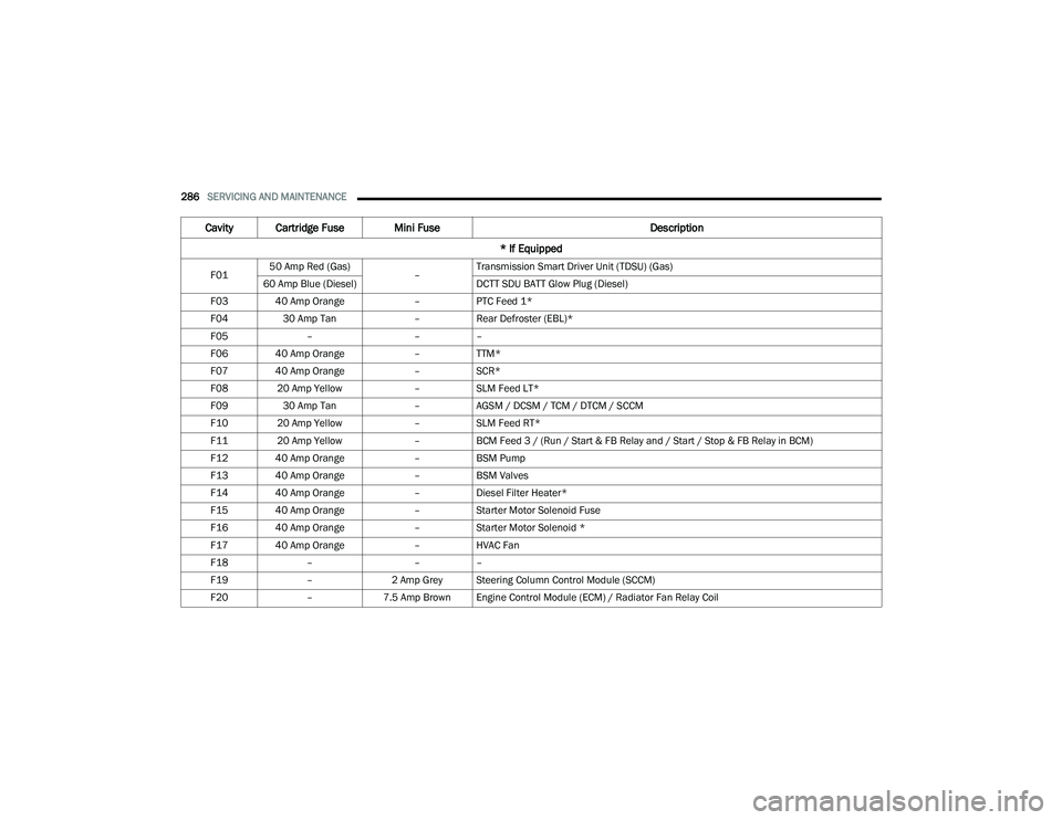
Cavity Cartridge Fuse Mini Fuse Description
* If Equipped
F01 50 Amp Red (Gas)
–Transmission Smart Driver Unit (TDSU) (Gas)
60 Amp Blue (Diesel) DCTT SDU BATT Glow Plug (Diesel)
F03 40 Amp Orange –PTC Feed 1*
F04 30 Amp Tan –Rear Defroster (EBL)*
F05 – ––
F06 40 Amp Orange –TTM*
F07 40 Amp Orange –SCR*
F08 20 Amp Yellow –SLM Feed LT*
F09 30 Amp Tan –AGSM / DCSM / TCM / DTCM / SCCM
F10 20 Amp Yellow –SLM Feed RT*
F11 20 Amp Yellow –BCM Feed 3 / (Run / Start & FB Relay and / Start / Stop & FB Relay in BCM)
F12 40 Amp Orange –BSM Pump
F13 40 Amp Orange –BSM Valves
F14 40 Amp Orange –Diesel Filter Heater*
F15 40 Amp Orange –Starter Motor Solenoid Fuse
F16 40 Amp Orange –Starter Motor Solenoid *
F17 40 Amp Orange –HVAC Fan
F18 – ––
F19 –2 Amp Grey Steering Column Control Module (SCCM)
F20 –7.5 Amp Brown Engine Control Module (ECM) / Radiator Fan Relay Coil
22_MP_OM_EN_USC_t.book Page 286
Page 292 of 344
290SERVICING AND MAINTENANCE
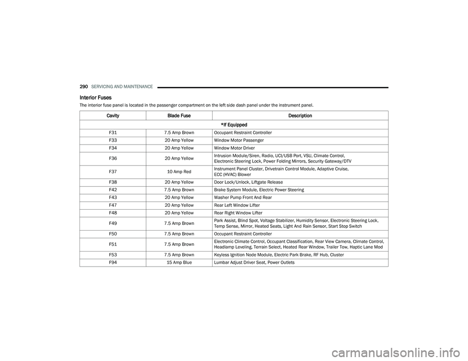
Interior Fuses
The interior fuse panel is located in the passenger compartment on the left side dash panel under the instrument panel.
CavityBlade Fuse Description
*If Equipped
F31 7.5 Amp Brown Occupant Restraint Controller
F33 20 Amp Yellow Window Motor Passenger
F34 20 Amp Yellow Window Motor Driver
F36 20 Amp YellowIntrusion Module/Siren, Radio, UCI/USB Port, VSU, Climate Control,
Electronic Steering Lock, Power Folding Mirrors, Security Gateway/DTV
F37 10 Amp RedInstrument Panel Cluster, Drivetrain Control Module, Adaptive Cruise,
ECC (HVAC) Blower
F38 20 Amp Yellow Door Lock/Unlock, Liftgate Release
F42 7.5 Amp Brown Brake System Module, Electric Power Steering
F43 20 Amp Yellow Washer Pump Front And Rear
F47 20 Amp Yellow Rear Left Window Lifter
F48 20 Amp Yellow Rear Right Window Lifter
F49 7.5 Amp BrownPark Assist, Blind Spot, Voltage Stabilizer, Humidity Sensor, Electronic Steering Lock,
Temp Sense, Mirror, Heated Seats, Light And Rain Sensor, Start Stop Switch
F50 7.5 Amp Brown Occupant Restraint Controller
F51 7.5 Amp BrownElectronic Climate Control, Occupant Classification, Rear View Camera, Climate Control,
Headlamp Leveling, Terrain Select, Heated Rear Window, Trailer Tow, Haptic Lane Mod
F53 7.5 Amp Brown Keyless Ignition Node Module, Electric Park Brake, RF Hub, Cluster
F94 15 Amp Blue Lumbar Adjust Driver Seat, Power Outlets
22_MP_OM_EN_USC_t.book Page 290
Page 334 of 344
332 G
Garage Door Opener (HomeLink)
.................... 40Gas Cap (Fuel Filler Cap)............................... 152Gasoline, (Fuel)............................................. 320Gasoline, Clean Air........................................ 320Gasoline, Reformulated................................. 320Gear Ranges.................................................. 108Gear Selector Override.................................. 262Glass Cleaning............................................... 318Gross Axle Weight Rating............................... 154Gross Vehicle Weight Rating.......................... 154GVWR............................................................ 153
H
Hazard Warning Flashers.............................. 244Head Restraints............................................... 34Head Rests...................................................... 34Headlights....................................................... 43Automatic.................................................... 45Cleaning.................................................... 316Delay........................................................... 45High Beam/Low Beam Select Switch.............................................. 43, 44Lights On Reminder.............................. 43, 45Passing................................................. 43, 45Switch.................................................. 43, 44Time Delay........................................... 43, 45Heated Mirrors......................................... 37, 39Heated Seats................................................... 33Heater, Engine Block..................................... 102
High Beam/Low Beam Select (Dimmer)
Switch.............................................................. 44Highway Assist System................................. 129Hill Descent Control...................................... 191Hill Descent Control Indicator....................... 191Hill Start Assist.............................................. 193Holder, Coin..................................................... 58HomeLink (Garage Door Opener)..................... 40Hood Prop........................................................ 66Hood Release.................................................. 66
I
Ignition............................................................. 17Switch.......................................................... 17Inside Rearview Mirror............................37, 244Instrument Cluster............... 73, 75, 76, 77, 80Audio........................................................... 85Descriptions......................................... 75, 77Display......................................................... 77Display And Messages................................. 81Driver Assist................................................ 83Fuel Economy.............................................. 84Menu Items................................................. 82Messages.................................................... 85Screen Setup............................................... 85Settings....................................................... 86StopStart..................................................... 85Trip Info....................................................... 84Vehicle Info.................................................. 83
Instrument Cluster DisplayDrive............................................................82Home...........................................................82Locations and Controls................................78Navigation...................................................84Off Road......................................................84Instrument Panel Lens Cleaning................... 318Interior Appearance Care.............................. 317Interior Fuses................................................ 290Interior Lights...................................................46InverterPower...........................................................60iPod/USB/MP3 Control....................................58
J
Jack Location................................................ 248Jack Operation..................................... 247, 250Jacking Instructions...................................... 250Jump Starting................................................ 258
K
Key FobArm The Alarm
.............................................21Disarm The Alarm........................................22Programming Additional Key Fobs...............16Remote Keyless Entry..................................14Key Fob Battery Service
(Remote Keyless Entry)....................................15
22_MP_OM_EN_USC_t.book Page 332
Page 335 of 344
333
Key Fob Programming
(Remote Keyless Entry)
................................... 16Keyless Enter 'n Go™................................ 14, 23Keys................................................................. 14
L
Lane Change And Turn Signals................. 43, 46Lane Change Assist.................................. 43, 46Lane Management System............................ 145LaneSense...................................................... 96Lap/Shoulder Belts....................................... 206Latches.......................................................... 242Hood........................................................... 66Leaks, Fluid................................................... 242Life Of Tires................................................... 308Liftgate..................................................... 66, 67Hands-Free.................................................. 69Liftgate Window Wiper/Washer....................... 49Light Bulbs..................................................... 242Lights............................................................. 2424WD Lock.................................................... 964WD Low..................................................... 96Active Speed Limiter Fault........................... 96Air Bag.......................................89, 213, 241Anti Lock Brake System............................... 92Automatic Headlights.................................. 45Automatic High Beam.................................. 97Battery Charge............................................ 90Battery Saver............................................... 46Brake Assist Warning................................ 191
Brake Warning............................................. 90Bulb Replacement.................................... 291Cruise................................................... 97, 98Daytime Running.................................. 43, 44Dimmer Switch, Headlight.................... 43, 44Door Open................................................... 90Drowsiness Detected.................................. 91Electric Power Steering Fault....................... 91Electronic Park Brake.................................. 93Electronic Stability Control........................... 93Electronic Throttle Control........................... 91Engine Temperature.................................... 91Exterior..................................................... 242Fog....................................................... 46, 96Forward Collision Warning........................... 96Fuel Cutoff................................................... 93Headlight Switch.......................................... 44Headlights............................................ 43, 44High Beam............................................ 44, 97High Beam/Low Beam Select............... 43, 44Hill Descent Control..................................... 97Hill Descent Control Indicator................... 191Hood Open.................................................. 91Immobilizer Fail VPS Electrical Alarm.......... 96Instrument Cluster................................ 43, 44Intensity Control................................... 46, 47Interior......................................................... 46LaneSense.................................... 93, 96, 97Liftgate Open............................................... 91Lights On Reminder.............................. 43, 45
Low Coolant Level........................................93Low Fuel......................................................93Low Washer Fluid........................................93Malfunction Indicator (Check Engine)..........93Oil Pressure.................................................91Oil Temperature...........................................92Park.............................................................96Passing.................................................43, 45Seat Belt Reminder.....................................92Security Alarm.............................................92Service...................................................... 291Service 4WD................................................94Service Forward Collision Warning...............94Service Stop Start........................................94Stop Start Active..........................................97Tire Pressure Monitoring (TPMS)....... 94, 201Towing Hook Breakdown.............................95Traction Control........................................ 191Transmission Fault......................................92Transmission Temperature..........................92Turn Signals......................... 43, 46, 97, 242Vanity Mirror................................................38Load Floor, Cargo.............................................70Loading Vehicle............................................. 153Tires.......................................................... 303Locks Auto Unlock.................................................25Child Protection...........................................25Power Door..................................................23Low Tire Pressure System............................. 201
11
22_MP_OM_EN_USC_t.book Page 333