Lamp rear JEEP COMPASS 2023 Owners Manual
[x] Cancel search | Manufacturer: JEEP, Model Year: 2023, Model line: COMPASS, Model: JEEP COMPASS 2023Pages: 344, PDF Size: 18.8 MB
Page 5 of 344
3
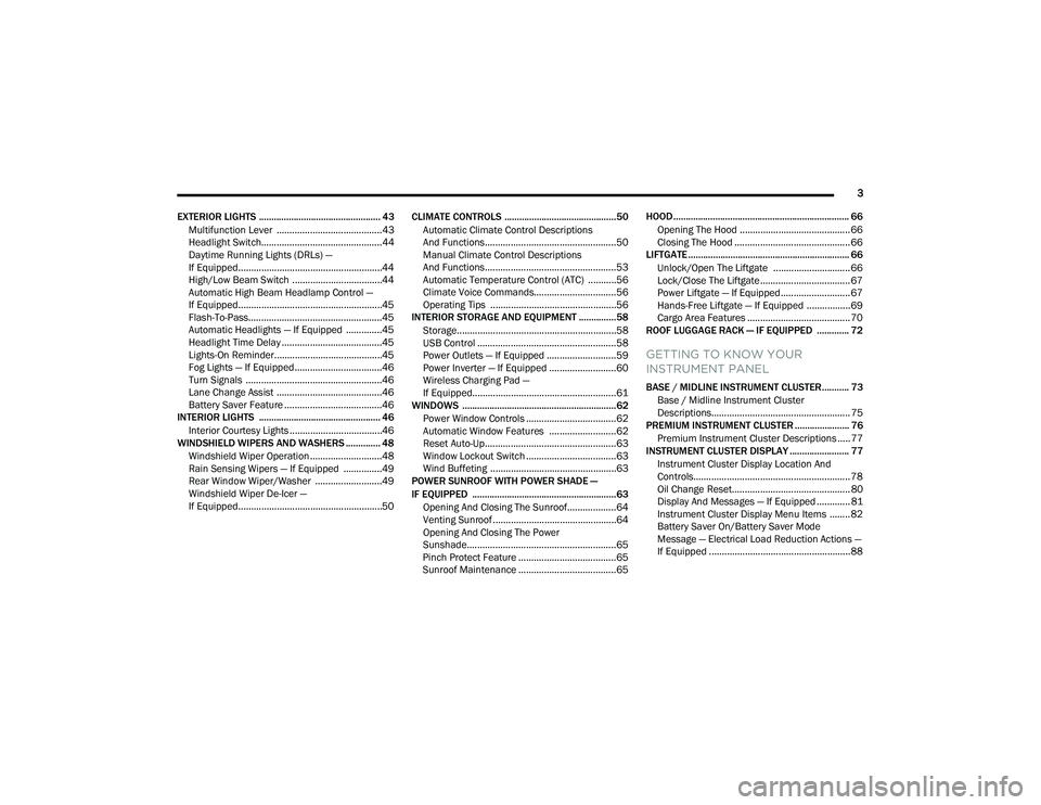
EXTERIOR LIGHTS ................................................. 43 Multifunction Lever .........................................43
Headlight Switch...............................................44
Daytime Running Lights (DRLs) —
If Equipped........................................................44
High/Low Beam Switch ...................................44
Automatic High Beam Headlamp Control —
If Equipped........................................................45
Flash-To-Pass....................................................45
Automatic Headlights — If Equipped ..............45
Headlight Time Delay .......................................45
Lights-On Reminder..........................................45
Fog Lights — If Equipped ..................................46
Turn Signals .....................................................46
Lane Change Assist .........................................46
Battery Saver Feature ......................................46
INTERIOR LIGHTS ................................................. 46
Interior Courtesy Lights ....................................46
WINDSHIELD WIPERS AND WASHERS .............. 48
Windshield Wiper Operation ............................48
Rain Sensing Wipers — If Equipped ...............49
Rear Window Wiper/Washer ..........................49
Windshield Wiper De-Icer —
If Equipped........................................................50 CLIMATE CONTROLS .............................................50
Automatic Climate Control Descriptions
And Functions ...................................................50
Manual Climate Control Descriptions
And Functions ...................................................53
Automatic Temperature Control (ATC) ...........56
Climate Voice Commands................................56
Operating Tips .................................................56
INTERIOR STORAGE AND EQUIPMENT ............... 58
Storage..............................................................58
USB Control ......................................................58
Power Outlets — If Equipped ...........................59
Power Inverter — If Equipped ..........................60
Wireless Charging Pad —
If Equipped........................................................61
WINDOWS ..............................................................62
Power Window Controls ...................................62
Automatic Window Features ..........................62
Reset Auto-Up...................................................63
Window Lockout Switch ...................................63
Wind Buffeting .................................................63
POWER SUNROOF WITH POWER SHADE —
IF EQUIPPED .......................................................... 63
Opening And Closing The Sunroof...................64
Venting Sunroof................................................64
Opening And Closing The Power
Sunshade..........................................................65
Pinch Protect Feature ......................................65
Sunroof Maintenance ......................................65 HOOD....................................................................... 66
Opening The Hood ........................................... 66
Closing The Hood ............................................. 66
LIFTGATE ................................................................. 66
Unlock/Open The Liftgate .............................. 66
Lock/Close The Liftgate................................... 67
Power Liftgate — If Equipped........................... 67
Hands-Free Liftgate — If Equipped ................. 69
Cargo Area Features ........................................ 70
ROOF LUGGAGE RACK — IF EQUIPPED ............. 72
GETTING TO KNOW YOUR
INSTRUMENT PANEL
BASE / MIDLINE INSTRUMENT CLUSTER........... 73
Base / Midline Instrument Cluster
Descriptions...................................................... 75
PREMIUM INSTRUMENT CLUSTER ...................... 76
Premium Instrument Cluster Descriptions ..... 77
INSTRUMENT CLUSTER DISPLAY ........................ 77
Instrument Cluster Display Location And
Controls............................................................. 78
Oil Change Reset.............................................. 80
Display And Messages — If Equipped ............. 81
Instrument Cluster Display Menu Items ........ 82
Battery Saver On/Battery Saver Mode
Message — Electrical Load Reduction Actions —
If Equipped .......................................................88
22_MP_OM_EN_USC_t.book Page 3
Page 99 of 344
GETTING TO KNOW YOUR INSTRUMENT PANEL97
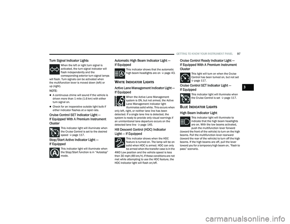
Turn Signal Indicator Lights
When the left or right turn signal is
activated, the turn signal indicator will
flash independently and the
corresponding exterior turn signal lamps
will flash. Turn signals can be activated when
the multifunction lever is moved down (left) or
up (right).
NOTE:
A continuous chime will sound if the vehicle is
driven more than 1 mile (1.6 km) with either
turn signal on.
Check for an inoperative outside light bulb if
either indicator flashes at a rapid rate.
Cruise Control SET Indicator Light —
If Equipped With A Premium Instrument
Cluster
This indicator light will illuminate when
the Cruise Control is set to the desired
speed Ú page 117.
Stop/Start Active Indicator Light —
If Equipped
This indicator light will illuminate when
the Stop/Start function is in “Autostop”
mode.
Automatic High Beam Indicator Light —
If Equipped
This indicator shows that the automatic
high beam headlights are on Úpage 43.
WHITE INDICATOR LIGHTS
Active Lane Management Indicator Light —
If Equipped
When the Active Lane Management
system is ON, but not armed, the Active
Lane Management indicator light
illuminates solid white. This occurs when
only left, right, or neither lane line has been
detected. If a single lane line is detected, the
system is ready to provide only visual warnings if
an unintentional lane departure occurs on the
detected lane line Ú page 145.
Hill Descent Control (HDC) Indicator
Light — If Equipped
This indicator shows when the HDC
feature is turned on. The lamp will be on
solid when HDC is armed. HDC can only
be armed when the transfer case is in the
4WD Low position and the vehicle speed is less
then 30 mph (48 km/h). If these conditions are not
met while attempting to use the HDC feature, the
HDC indicator light will flash on/off.
Cruise Control Ready Indicator Light —
If Equipped With A Premium Instrument
Cluster
This light will turn on when the Cruise
Control has been turned on, but not set
Ú page 117.
Cruise Control SET Indicator Light —
If Equipped
This indicator light will illuminate when
the Cruise Control is set Ú page 117.
BLUE INDICATOR LIGHTS
High Beam Indicator Light
This indicator light will illuminate to
indicate that the high beam headlights
are on. With the low beams activated,
push the multifunction lever forward
(toward the front of the vehicle) to turn on the high
beams. Pull the multifunction lever rearward
(toward the rear of the vehicle) to turn off the high
beams. If the high beams are off, pull the lever
toward you for a temporary high beam on, “flash to
pass” scenario.
3
22_MP_OM_EN_USC_t.book Page 97
Page 106 of 344
104STARTING AND OPERATING
(Continued)
brake is fully disengaged, the Brake Warning Light
in the instrument cluster and the LED indicator on
the switch will extinguish.
NOTE:When parking on a hill, it is important to turn the
front wheels toward the curb on a downhill grade
and away from the curb on an uphill grade. Apply
the parking brake before placing the gear selector
in PARK, otherwise the load on the transmission
locking mechanism may make it difficult to move
the gear selector out of PARK. The parking brake
should always be applied whenever the driver is
not in the vehicle.
If exceptional circumstances should make it
necessary to engage the parking brake while the
vehicle is in motion, maintain upward pressure on
the EPB switch for as long as engagement is
desired. The BRAKE warning lamp will illuminate,
and a continuous chime will sound. The rear stop
lamps will also be illuminated automatically while
the vehicle remains in motion.
To disengage the parking brake while the vehicle is
in motion, release the switch. If the vehicle is
brought to a complete stop using the parking
brake, when the vehicle reaches approximately
3 mph, (5 km/h) the parking brake will remain
engaged.
WARNING!
Do not rely on the parking brake to operate
effectively if the rear brakes have been
immersed in water or mud.
Never use the PARK position as a substitute
for the parking brake. Always apply the
parking brake fully when parked to guard
against vehicle movement and possible injury
or damage.
When leaving the vehicle, always remove the
key fob from the ignition and lock your vehicle.
Never leave children alone in a vehicle, or with
access to an unlocked vehicle. Allowing chil
-
dren to be in a vehicle unattended is
dangerous for a number of reasons. A child or
others could be seriously or fatally injured.
Children should be warned not to touch the
parking brake, brake pedal or the gear
selector.
Do not leave the key fob in or near the vehicle,
or in a location accessible to children, and do
not leave the ignition of a vehicle equipped
with Keyless Enter ’n Go™ in the ACC or ON/
RUN position. A child could operate power
windows, other controls, or move the vehicle.
Be sure the parking brake is fully disengaged
before driving; failure to do so can lead to
brake failure and a collision.
Always fully apply the parking brake when
leaving your vehicle, or it may roll and cause
damage or injury. Also be certain to leave the
transmission in PARK. Failure to do so may
allow the vehicle to roll and cause damage or
injury.
WARNING!CAUTION!
If the Brake System Warning Light remains on
with the parking brake released, a brake system
malfunction is indicated. Have the brake system
serviced by an authorized dealer immediately.
WARNING!
Driving the vehicle with the parking brake
engaged, or repeated use of the parking brake
to slow the vehicle, may cause serious damage
to the brake system. Be sure the parking brake
is fully disengaged before driving; failure to do
so can lead to brake failure and a collision.
22_MP_OM_EN_USC_t.book Page 104
Page 108 of 344

106STARTING AND OPERATING
(Continued)
Brake Service Mode
We recommend having your brakes serviced by an
authorized dealer.
You should only make repairs for which you have
the knowledge and the right equipment. You
should only enter Brake Service Mode during
brake service.
When servicing your rear brakes, it may be
necessary for you or your technician to push the
rear piston into the rear caliper bore. With the EPB
system, this can only be done after retracting the
EPB actuator. The actuator retraction can be done
easily by entering the Brake Service Mode through
the Uconnect Settings in your vehicle. This
menu-based system will guide you through the
steps necessary to retract the EPB actuator in
order to perform rear brake service.
Service Mode has requirements that must be met
in order to be activated:
The vehicle must be at a standstill.
The parking brake must be disabled.
The transmission must be in PARK or NEUTRAL.
The EPB switch not activated.
The vehicle in ignition ON/RUN position.
The brake pedal not pressed.While in Service Mode, the EPB fault lamp will flash
continuously while the ignition switch is ON/RUN.
NOTE:A dedicated message will appear in the instrument
cluster display if Brake Service Mode cannot be
activated.
When brake service work is complete, the following
steps must be followed to reset the parking brake
system to normal operation:
Ensure the vehicle is at a standstill.
Press the brake pedal with moderate force.
Apply the EPB Switch.
NOTE:A dedicated message will appear in the instrument
cluster display if Brake Service Mode cannot be
deactivated.
AUTOMATIC TRANSMISSION
You must press and hold the brake pedal while
shifting out of PARK.
WARNING!
You can be badly injured working on or around a
motor vehicle. Do only that service work for
which you have the knowledge and the right
equipment. If you have any doubt about your
ability to perform a service job, take your vehicle
to a competent mechanic.
WARNING!
Never use the PARK (P) position as a substi
-
tute for the parking brake. Always apply the
parking brake fully when exiting the vehicle to
guard against vehicle movement and possible
injury or damage.
Your vehicle could move and injure you and
others if it is not in PARK. Check by trying to
move the gear selector out of PARK with the
brake pedal released. Make sure the trans -
mission is in PARK before exiting the vehicle.
It is dangerous to shift out of PARK or
NEUTRAL (N) if the engine speed is higher
than idle speed. If your foot is not firmly
pressing the brake pedal, the vehicle could
accelerate quickly forward or in reverse. You
could lose control of the vehicle and hit
someone or something. Only shift into gear
when the engine is idling normally and your
foot is firmly pressing the brake pedal.
The vehicle may not engage a newly selected
gear when shifting between PARK, REVERSE
(R), or DRIVE (D) if the vehicle is moving while
shifting.
22_MP_OM_EN_USC_t.book Page 106
Page 193 of 344
SAFETY191
To turn ESC on again, momentarily push the ESC
OFF button. This will restore the “ESC On” mode of
operation.
NOTE:The “ESC OFF” message will display and an audible
chime will sound when the gear selector is placed
into the PARK position from any other position, and
then moved out of the PARK position. This will
occur even if the message was previously cleared.
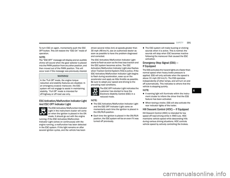
ESC Activation/Malfunction Indicator Light
And ESC OFF Indicator Light
The ESC Activation/Malfunction Indicator
Light in the instrument cluster will come
on when the ignition is placed in the ON
mode. It should go out with the engine
running. If the ESC Activation/Malfunction
Indicator Light comes on continuously with the
engine running, a malfunction has been detected
in the ESC system. If this light remains on after
several ignition cycles, and the vehicle has been driven several miles (km) at speeds greater than
30 mph (48 km/h), see an authorized dealer as
soon as possible to have the problem diagnosed
and corrected.
The ESC Activation/Malfunction Indicator Light
starts to flash as soon as the tires lose traction and
the ESC system becomes active. The ESC
Activation/Malfunction Indicator Light also flashes
when Traction Control System (TCS) is active. If the
ESC Activation/Malfunction Indicator Light begins
to flash during acceleration, ease up on the
accelerator and apply as little throttle as possible.
Be sure to adapt your speed and driving to the
prevailing road conditions.
The ESC OFF Indicator Light indicates the
customer has elected to have the
Electronic Stability Control (ESC) in a
reduced mode.
NOTE:
The ESC Activation/Malfunction Indicator Light
and the ESC OFF Indicator Light come on
momentarily each time the ignition is placed in
the ON/RUN position.
Each time the ignition is placed in the ON/RUN
position, the ESC system will be on even if it was
turned off previously.
The ESC system will make buzzing or clicking
sounds when it is active. This is normal; the
sounds will stop when ESC becomes inactive
following the maneuver that caused the ESC
activation.
Emergency Stop Signal (ESS) —
If Equipped
The ESS activates the hazard lights at a faster than
normal speed when heavy brake pressure is
applied. ESS will only activate when the speed is
above 31 mph (50 km/h). The ESS operates
independently of other lamps, and will turn on and
off automatically. This indicates to others that the
vehicle is stopping quickly.
NOTE:
A warning light will illuminate within the instru -
ment cluster to inform the driver that the ESS
feature has been activated.
When towing a trailer, ESS will also activate the
rear indicator lights of the trailer.
Hill Descent Control (HDC) — If Equipped
Hill Descent Control (HDC) is intended for low
speed off-road driving while in 4WD Low. HDC
maintains vehicle speed while descending hills
during various driving situations. HDC controls
vehicle speed by actively controlling the brakes.
WARNING!
In the "Full Off" mode, the engine torque
reduction and stability features are disabled. In
an emergency evasive maneuver, the ESC
system will not engage to assist in maintaining
stability. “Full Off” mode is intended for
off-highway or off-road use only.
6
22_MP_OM_EN_USC_t.book Page 191
Page 266 of 344
264IN CASE OF EMERGENCY
TOWING A DISABLED VEHICLE
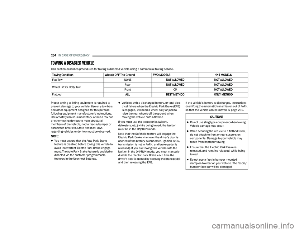
This section describes procedures for towing a disabled vehicle using a commercial towing service.
Proper towing or lifting equipment is required to
prevent damage to your vehicle. Use only tow bars
and other equipment designed for this purpose,
following equipment manufacturer’s instructions.
Use of safety chains is mandatory. Attach a tow bar
or other towing devices to main structural
members of the vehicle, not to fascia/bumper or
associated brackets. State and local laws
regarding vehicles under tow must be observed.
NOTE:
You must ensure that the Auto Park Brake
feature is disabled before towing this vehicle to
avoid inadvertent Electric Park Brake engage -
ment. The Auto Park Brake feature is enabled or
disabled via the customer programmable
features in the Uconnect Settings.
Vehicles with a discharged battery, or total elec -
trical failure when the Electric Park Brake (EPB)
is engaged, will need a wheel dolly or jack to
raise the rear wheels off the ground when
moving the vehicle onto a flatbed.
If you must use the accessories (wipers,
defrosters, etc.) while being towed, the ignition
must be in the ON/RUN mode.
Note that the Safehold feature will engage the
Electric Park Brake whenever the driver's door is
opened (if the battery is connected, ignition is ON,
transmission is not in PARK, and brake pedal is
released). If you are towing this vehicle with the
ignition in the ON/RUN mode, you must manually
disable the Electric Park Brake each time the
driver's door is opened by pressing the brake pedal
and then releasing the EPB. If the vehicle’s battery is discharged, instructions
on shifting the automatic transmission out of PARK
so that the vehicle can be moved Ú
page 262.
Towing Condition
Wheels OFF The GroundFWD MODELS 4X4 MODELS
Flat Tow NONENOT ALLOWED NOT ALLOWED
Wheel Lift Or Dolly Tow Rear
NOT ALLOWED NOT ALLOWED
Front OKNOT ALLOWED
Flatbed ALLBEST METHOD ONLY METHOD
CAUTION!
Do not use sling-type equipment when towing.
Vehicle damage may occur.
When securing the vehicle to a flatbed truck,
do not attach to front or rear suspension
components. Damage to your vehicle may
result from improper towing.
Ensure that the Electric Park Brake is
released, and remains released, while being
towed.
Do not use a fascia/bumper mounted
clamp-on tow bar on your vehicle. The fascia/
bumper face bar will be damaged.
22_MP_OM_EN_USC_t.book Page 264
Page 292 of 344
290SERVICING AND MAINTENANCE
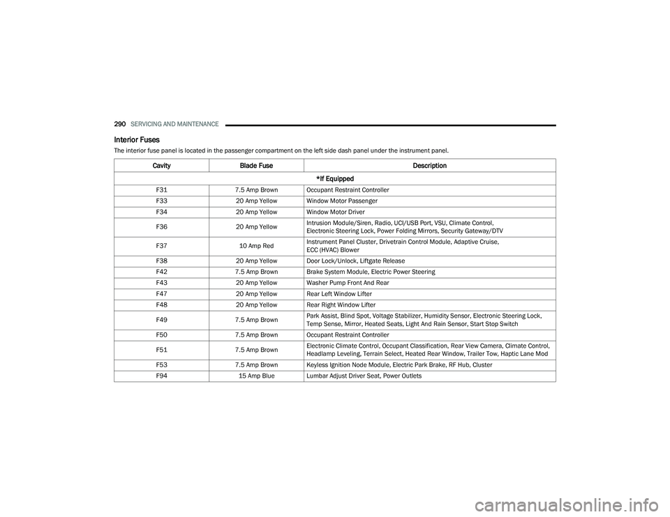
Interior Fuses
The interior fuse panel is located in the passenger compartment on the left side dash panel under the instrument panel.
CavityBlade Fuse Description
*If Equipped
F31 7.5 Amp Brown Occupant Restraint Controller
F33 20 Amp Yellow Window Motor Passenger
F34 20 Amp Yellow Window Motor Driver
F36 20 Amp YellowIntrusion Module/Siren, Radio, UCI/USB Port, VSU, Climate Control,
Electronic Steering Lock, Power Folding Mirrors, Security Gateway/DTV
F37 10 Amp RedInstrument Panel Cluster, Drivetrain Control Module, Adaptive Cruise,
ECC (HVAC) Blower
F38 20 Amp Yellow Door Lock/Unlock, Liftgate Release
F42 7.5 Amp Brown Brake System Module, Electric Power Steering
F43 20 Amp Yellow Washer Pump Front And Rear
F47 20 Amp Yellow Rear Left Window Lifter
F48 20 Amp Yellow Rear Right Window Lifter
F49 7.5 Amp BrownPark Assist, Blind Spot, Voltage Stabilizer, Humidity Sensor, Electronic Steering Lock,
Temp Sense, Mirror, Heated Seats, Light And Rain Sensor, Start Stop Switch
F50 7.5 Amp Brown Occupant Restraint Controller
F51 7.5 Amp BrownElectronic Climate Control, Occupant Classification, Rear View Camera, Climate Control,
Headlamp Leveling, Terrain Select, Heated Rear Window, Trailer Tow, Haptic Lane Mod
F53 7.5 Amp Brown Keyless Ignition Node Module, Electric Park Brake, RF Hub, Cluster
F94 15 Amp Blue Lumbar Adjust Driver Seat, Power Outlets
22_MP_OM_EN_USC_t.book Page 290
Page 293 of 344
SERVICING AND MAINTENANCE291
BULB REPLACEMENT
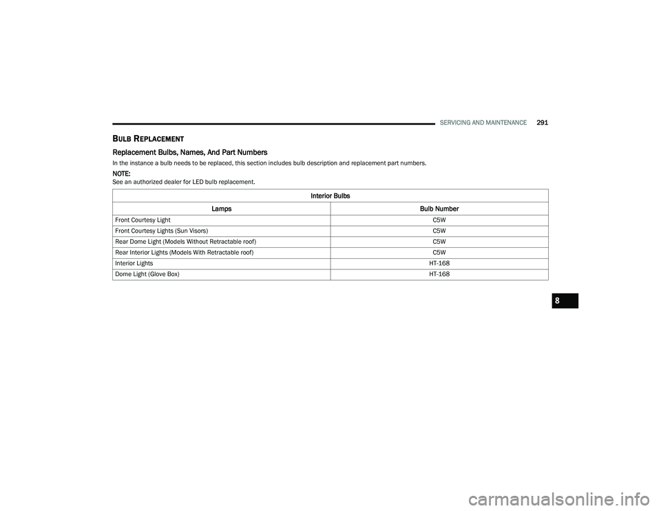
Replacement Bulbs, Names, And Part Numbers
In the instance a bulb needs to be replaced, this section includes bulb description and replacement part numbers.
NOTE:See an authorized dealer for LED bulb replacement.
Interior Bulbs
Lamps Bulb Number
Front Courtesy Light C5W
Front Courtesy Lights (Sun Visors) C5W
Rear Dome Light (Models Without Retractable roof) C5W
Rear Interior Lights (Models With Retractable roof) C5W
Interior Lights HT-168
Dome Light (Glove Box) HT-168
8
22_MP_OM_EN_USC_t.book Page 291
Page 295 of 344
SERVICING AND MAINTENANCE293
Replacing Exterior Bulbs
Turn Signal Light/Position Lights (Base)
To replace the bulbs proceed as follows:
1. Open hood.
2. Reach behind headlamp near the radiator.
3. Remove the electrical connectors.
4. For the turn signal bulb, rotate in a counter -
clockwise direction and remove the bulb and
bulb socket. Pull the bulb axially to remove it
from the socket.
5. Install the bulb and sockets and rotate them clockwise making sure that it is properly
locked.
6. Reconnect the electrical connectors.
7. Close hood.
NOTE:It is advised referring to an authorized dealer. Front Fog Lights (Base)
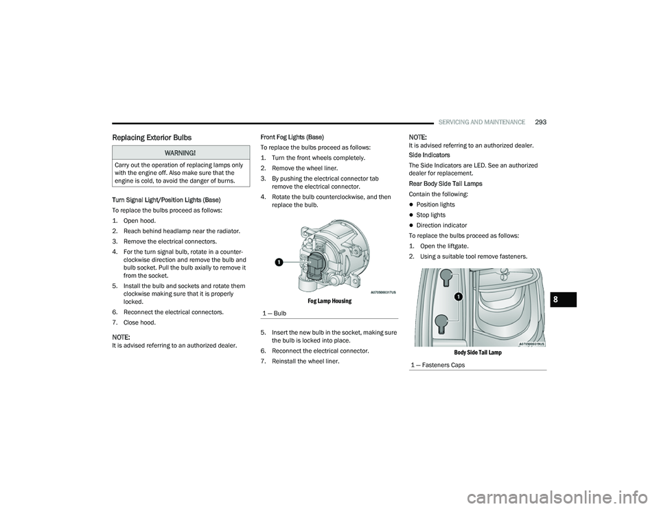
To replace the bulbs proceed as follows:
1. Turn the front wheels completely.
2. Remove the wheel liner.
3. By pushing the electrical connector tab
remove the electrical connector.
4. Rotate the bulb counterclockwise, and then replace the bulb.
Fog Lamp Housing
5. Insert the new bulb in the socket, making sure the bulb is locked into place.
6. Reconnect the electrical connector.
7. Reinstall the wheel liner.
NOTE:It is advised referring to an authorized dealer.
Side Indicators
The Side Indicators are LED. See an authorized
dealer for replacement.
Rear Body Side Tail Lamps
Contain the following:
Position lights
Stop lights
Direction indicator
To replace the bulbs proceed as follows:
1. Open the liftgate.
2. Using a suitable tool remove fasteners.
Body Side Tail Lamp
WARNING!
Carry out the operation of replacing lamps only
with the engine off. Also make sure that the
engine is cold, to avoid the danger of burns.
1 — Bulb
1 — Fasteners Caps
8
22_MP_OM_EN_USC_t.book Page 293
Page 296 of 344
294SERVICING AND MAINTENANCE
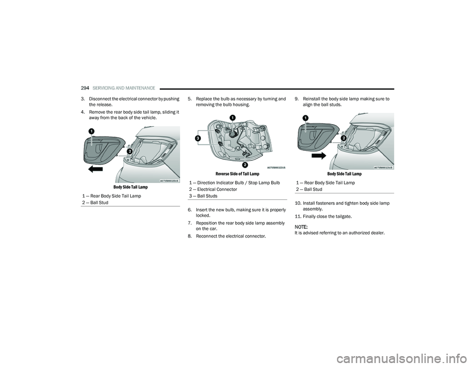
3. Disconnect the electrical connector by pushing the release.
4. Remove the rear body side tail lamp, sliding it away from the back of the vehicle.
Body Side Tail Lamp
5. Replace the bulb as necessary by turning and
removing the bulb housing.
Reverse Side of Tail Lamp
6. Insert the new bulb, making sure it is properly locked.
7. Reposition the rear body side lamp assembly on the car.
8. Reconnect the electrical connector. 9. Reinstall the body side lamp making sure to
align the ball studs.
Body Side Tail Lamp
10. Install fasteners and tighten body side lamp assembly.
11. Finally close the tailgate.
NOTE:It is advised referring to an authorized dealer.
1 — Rear Body Side Tail Lamp
2 — Ball Stud
1 — Direction Indicator Bulb / Stop Lamp Bulb
2 — Electrical Connector
3 — Ball Studs1 — Rear Body Side Tail Lamp
2 — Ball Stud
22_MP_OM_EN_USC_t.book Page 294