headlamp JEEP COMPASS 2023 Owners Manual
[x] Cancel search | Manufacturer: JEEP, Model Year: 2023, Model line: COMPASS, Model: JEEP COMPASS 2023Pages: 344, PDF Size: 18.8 MB
Page 5 of 344
3
EXTERIOR LIGHTS ................................................. 43 Multifunction Lever .........................................43
Headlight Switch...............................................44
Daytime Running Lights (DRLs) —
If Equipped........................................................44
High/Low Beam Switch ...................................44
Automatic High Beam Headlamp Control —
If Equipped........................................................45
Flash-To-Pass....................................................45
Automatic Headlights — If Equipped ..............45
Headlight Time Delay .......................................45
Lights-On Reminder..........................................45
Fog Lights — If Equipped ..................................46
Turn Signals .....................................................46
Lane Change Assist .........................................46
Battery Saver Feature ......................................46
INTERIOR LIGHTS ................................................. 46
Interior Courtesy Lights ....................................46
WINDSHIELD WIPERS AND WASHERS .............. 48
Windshield Wiper Operation ............................48
Rain Sensing Wipers — If Equipped ...............49
Rear Window Wiper/Washer ..........................49
Windshield Wiper De-Icer —
If Equipped........................................................50 CLIMATE CONTROLS .............................................50
Automatic Climate Control Descriptions
And Functions ...................................................50
Manual Climate Control Descriptions
And Functions ...................................................53
Automatic Temperature Control (ATC) ...........56
Climate Voice Commands................................56
Operating Tips .................................................56
INTERIOR STORAGE AND EQUIPMENT ............... 58
Storage..............................................................58
USB Control ......................................................58
Power Outlets — If Equipped ...........................59
Power Inverter — If Equipped ..........................60
Wireless Charging Pad —
If Equipped........................................................61
WINDOWS ..............................................................62
Power Window Controls ...................................62
Automatic Window Features ..........................62
Reset Auto-Up...................................................63
Window Lockout Switch ...................................63
Wind Buffeting .................................................63
POWER SUNROOF WITH POWER SHADE —
IF EQUIPPED .......................................................... 63
Opening And Closing The Sunroof...................64
Venting Sunroof................................................64
Opening And Closing The Power
Sunshade..........................................................65
Pinch Protect Feature ......................................65
Sunroof Maintenance ......................................65 HOOD....................................................................... 66
Opening The Hood ........................................... 66
Closing The Hood ............................................. 66
LIFTGATE ................................................................. 66
Unlock/Open The Liftgate .............................. 66
Lock/Close The Liftgate................................... 67
Power Liftgate — If Equipped........................... 67
Hands-Free Liftgate — If Equipped ................. 69
Cargo Area Features ........................................ 70
ROOF LUGGAGE RACK — IF EQUIPPED ............. 72
GETTING TO KNOW YOUR
INSTRUMENT PANEL
BASE / MIDLINE INSTRUMENT CLUSTER........... 73
Base / Midline Instrument Cluster
Descriptions...................................................... 75
PREMIUM INSTRUMENT CLUSTER ...................... 76
Premium Instrument Cluster Descriptions ..... 77
INSTRUMENT CLUSTER DISPLAY ........................ 77
Instrument Cluster Display Location And
Controls............................................................. 78
Oil Change Reset.............................................. 80
Display And Messages — If Equipped ............. 81
Instrument Cluster Display Menu Items ........ 82
Battery Saver On/Battery Saver Mode
Message — Electrical Load Reduction Actions —
If Equipped .......................................................88
22_MP_OM_EN_USC_t.book Page 3
Page 46 of 344
44GETTING TO KNOW YOUR VEHICLE
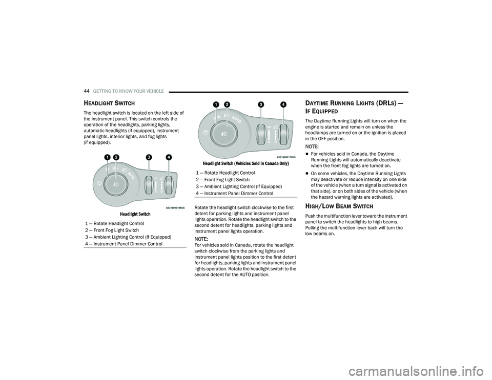
HEADLIGHT SWITCH
The headlight switch is located on the left side of
the instrument panel. This switch controls the
operation of the headlights, parking lights,
automatic headlights (if equipped), instrument
panel lights, interior lights, and fog lights
(if equipped).
Headlight Switch Headlight Switch (Vehicles Sold In Canada Only)
Rotate the headlight switch clockwise to the first
detent for parking lights and instrument panel
lights operation. Rotate the headlight switch to the
second detent for headlights, parking lights and
instrument panel lights operation.
NOTE:For vehicles sold in Canada, rotate the headlight
switch clockwise from the parking lights and
instrument panel lights position to the first detent
for headlights, parking lights and instrument panel
lights operation. Rotate the headlight switch to the
second detent for the AUTO position.
DAYTIME RUNNING LIGHTS (DRLS) —
I
F EQUIPPED
The Daytime Running Lights will turn on when the
engine is started and remain on unless the
headlamps are turned on or the ignition is placed
in the OFF position.
NOTE:
For vehicles sold in Canada, the Daytime
Running Lights will automatically deactivate
when the front fog lights are turned on.
On some vehicles, the Daytime Running Lights
may deactivate or reduce intensity on one side
of the vehicle (when a turn signal is activated on
that side), or on both sides of the vehicle (when
the hazard warning lights are activated).
HIGH/LOW BEAM SWITCH
Push the multifunction lever toward the instrument
panel to switch the headlights to high beams.
Pulling the multifunction lever back will turn the
low beams on.
1 — Rotate Headlight Control
2 — Front Fog Light Switch
3 — Ambient Lighting Control (If Equipped)
4 — Instrument Panel Dimmer Control
1 — Rotate Headlight Control
2 — Front Fog Light Switch
3 — Ambient Lighting Control (If Equipped)
4 — Instrument Panel Dimmer Control
22_MP_OM_EN_USC_t.book Page 44
Page 47 of 344
GETTING TO KNOW YOUR VEHICLE45
AUTOMATIC HIGH BEAM HEADLAMP
C
ONTROL — IF EQUIPPED
The Automatic High Beam Headlamp Control
system provides increased forward lighting at night
by automating high beam control through the use
of a digital camera mounted on the windshield.
This camera detects vehicle specific light and
automatically switches from high beams to low
beams until the approaching vehicle is out of view.
NOTE:
The Automatic High Beam Headlamp Control
can be turned on or off through Uconnect
Settings Ú page 165.
Broken, muddy, or obstructed headlights and
taillights of vehicles in the field of view will
cause headlights to remain on longer (closer to
the vehicle). Also, dirt, film, and other obstruc -
tions on the windshield or camera lens will
cause the system to function improperly.
FLASH-TO-PASS
You can signal another vehicle with your headlights
by lightly pulling the multifunction lever toward you.
This will cause the high beam headlights to turn on,
and remain on, until the lever is released.
AUTOMATIC HEADLIGHTS — IF EQUIPPED
This system automatically turns the headlights on
or off according to ambient light levels. To turn the
system on, rotate the headlight switch clockwise to
the last detent for automatic headlight operation.
When the system is on, the headlight time delay
feature is also on. This means the headlights will
stay on for up to 90 seconds after you place the
ignition into the OFF position. To turn the
automatic system off, move the headlight switch
out of the AUTO position.
NOTE:The engine must be running before the headlights
will come on in the automatic mode.
HEADLIGHT TIME DELAY
To assist when exiting the vehicle, the headlight
delay feature will leave the headlights on for up to
90 seconds.
To activate the delay feature, place the ignition in
the OFF position while the headlights are still on.
Then, turn off the headlights within 45 seconds.
The delay interval begins when the headlight
switch is turned off. Headlight delay can be cancelled by either turning
the headlights or parking lights on, or placing the
ignition in the ON/RUN position.
If you turn the headlights off before the ignition,
they will turn off in the normal manner.
NOTE:
The lights must be turned off within 45 seconds
of placing the ignition in the OFF position to acti
-
vate this feature. If the headlight switch is in the
AUTO position prior to placing the ignition in the
OFF position, there is no need to turn the head-
light switch to off to activate Headlight Delay.
The headlight delay timing is programmable
through Uconnect Settings Ú page 165.
LIGHTS-ON REMINDER
If the headlights or parking lights are on after the
ignition is in the OFF position, a chime will sound to
alert the driver when the driver's door is opened.
2
22_MP_OM_EN_USC_t.book Page 45
Page 104 of 344
102STARTING AND OPERATING
STOPPING THE ENGINE
Vehicles Equipped With Electronic Key (Keyless
Enter ’n Go™):
To shut off the engine with vehicle speed greater
than 5 mph (8 km/h), you must push and hold the
ignition or push the ENGINE START/STOP button
three times consecutively within a few seconds.
The engine will shut down, and the ignition will be
placed in the ON/RUN position. Turning off the car (placing the ignition from the
ON/RUN position to the OFF position), the power
supply to the accessories are maintained for a
period of three minutes.
Opening the driver’s side door with the ignition in
ON/RUN will sound a short chime that reminds the
driver to place the ignition to OFF.
When the ignition is in the OFF position, the
window switches remain active for three minutes.
Opening a front door will cancel this function.
After severe driving, idle the engine to allow the
temperature inside the engine compartment to
cool before shutting off the engine.
ENGINE BLOCK HEATER — IF EQUIPPED
The engine block heater warms the engine and
permits quicker starts in cold weather.
Connect the cord to a 110-115 Volt AC electrical
outlet with a grounded, three-wire extension cord.
For ambient temperatures below 0°F (-18°C), the
engine block heater is recommended. For ambient
temperatures below -20°F (-29°C), the engine
block heater is required.
The engine block heater cord is routed under the
hood, behind to the driver’s side headlamp.
NOTE:
The engine block heater cord is a factory
installed option. If your vehicle is not equipped,
heater cords are available from an authorized
dealer.
The engine block heater will require 110 Volt AC
and 6.5 Amps to activate the heater element.
The engine block heater must be plugged in at
least one hour to have an adequate warming
effect on the engine.
ENGINE BREAK-IN RECOMMENDATIONS
A long break-in period is not required for the engine
and drivetrain (transmission and axle) in your
vehicle.
Drive moderately during the first 300 miles
(500 km). After the initial 60 miles (100 km),
speeds up to 50 or 55 mph (80 or 90 km/h) are
desirable.
WARNING!
Never pour fuel or other flammable liquid into
the throttle body air inlet opening in an
attempt to start the vehicle. This could result
in flash fire causing serious personal injury.
Do not attempt to push or tow your vehicle to
get it started. Vehicles equipped with an auto -
matic transmission cannot be started this
way. Unburned fuel could enter the catalytic
converter and once the engine has started,
ignite and damage the converter and vehicle.
If the vehicle has a discharged battery,
booster cables may be used to obtain a start
from a booster battery or the battery in
another vehicle. This type of start can be
dangerous if done improperly Ú page 258.
WARNING!
Remember to disconnect the engine block
heater cord before driving. Damage to the
110-115 Volt electrical cord could cause
electrocution.
22_MP_OM_EN_USC_t.book Page 102
Page 226 of 344

224SAFETY
Enhanced Accident Response System
In the event of an impact, if the communication
network remains intact, and the power remains
intact, depending on the nature of the event, the
Occupant Restraint Controller (ORC) will determine
whether to have the Enhanced Accident Response
System perform the following functions:
Cut off fuel to the engine (if equipped)
Cut off battery power to the electric motor
(if equipped)
Flash hazard lights as long as the battery has
power
Turn on the interior lights, which remain on as
long as the battery has power or for 15 minutes
from the intervention of the Enhanced Accident
Response System
Unlock the power door locks Your vehicle may also be designed to perform any
of these other functions in response to the
Enhanced Accident Response System:
Turn off the Fuel Filter Heater, Turn off the HVAC
Blower Motor, Close the HVAC Circulation Door
Cut off battery power to the:
Engine
Electric Motor (if equipped)
Electric power steering
Brake booster
Electric park brake
Automatic transmission gear selector
Horn
Front wiper
Headlamp washer pump (if equipped)
NOTE:After an accident, remember to cycle the ignition to
the STOP (OFF/LOCK) position and remove the key
from the ignition switch to avoid draining the
battery. Carefully check the vehicle for fuel leaks in
the engine compartment and on the ground near
the engine compartment and fuel tank before
resetting the system and starting the engine. If
there are no fuel leaks or damage to the vehicle
electrical devices (e.g. headlights) after an
accident, reset the system by following the
procedure described below. If you have any doubt,
contact an authorized dealer.
22_MP_OM_EN_USC_t.book Page 224
Page 292 of 344
290SERVICING AND MAINTENANCE
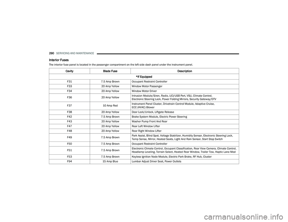
Interior Fuses
The interior fuse panel is located in the passenger compartment on the left side dash panel under the instrument panel.
CavityBlade Fuse Description
*If Equipped
F31 7.5 Amp Brown Occupant Restraint Controller
F33 20 Amp Yellow Window Motor Passenger
F34 20 Amp Yellow Window Motor Driver
F36 20 Amp YellowIntrusion Module/Siren, Radio, UCI/USB Port, VSU, Climate Control,
Electronic Steering Lock, Power Folding Mirrors, Security Gateway/DTV
F37 10 Amp RedInstrument Panel Cluster, Drivetrain Control Module, Adaptive Cruise,
ECC (HVAC) Blower
F38 20 Amp Yellow Door Lock/Unlock, Liftgate Release
F42 7.5 Amp Brown Brake System Module, Electric Power Steering
F43 20 Amp Yellow Washer Pump Front And Rear
F47 20 Amp Yellow Rear Left Window Lifter
F48 20 Amp Yellow Rear Right Window Lifter
F49 7.5 Amp BrownPark Assist, Blind Spot, Voltage Stabilizer, Humidity Sensor, Electronic Steering Lock,
Temp Sense, Mirror, Heated Seats, Light And Rain Sensor, Start Stop Switch
F50 7.5 Amp Brown Occupant Restraint Controller
F51 7.5 Amp BrownElectronic Climate Control, Occupant Classification, Rear View Camera, Climate Control,
Headlamp Leveling, Terrain Select, Heated Rear Window, Trailer Tow, Haptic Lane Mod
F53 7.5 Amp Brown Keyless Ignition Node Module, Electric Park Brake, RF Hub, Cluster
F94 15 Amp Blue Lumbar Adjust Driver Seat, Power Outlets
22_MP_OM_EN_USC_t.book Page 290
Page 294 of 344
292SERVICING AND MAINTENANCE
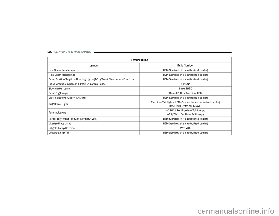
Exterior Bulbs
Lamps Bulb Number
Low Beam Headlamps LED (Serviced at an authorized dealer)
High Beam Headlamps LED (Serviced at an authorized dealer)
Front Position/Daytime Running Lights (DRL)/Front Directional - Premium LED (Serviced at an authorized dealer)
Front Direction Indicator & Position Lamps - Base 7442NA
Side Marker Lamp Base:2825
Front Fog Lamps Base: H11LL/ Premium LED
Side Indicators (Side View Mirror) LED (Serviced at an authorized dealer)
Tail/Brake Lights Premium Tail Lights: LED (Serviced at an authorized dealer)
Base Tail Lights: W21/5WLL
Turn Indicators W21WLL For Premium Tail Lamps
W21/5WLL For Base Tail Lamps
Center High Mounted Stop Lamp (CHMSL) LED (Serviced at an authorized dealer)
License Plate Lamp LED (Serviced at an authorized dealer)
Liftgate Lamp Reverse W21WLL
Liftgate Lamp Tail LED (Serviced at an authorized dealer)
22_MP_OM_EN_USC_t.book Page 292
Page 295 of 344
SERVICING AND MAINTENANCE293
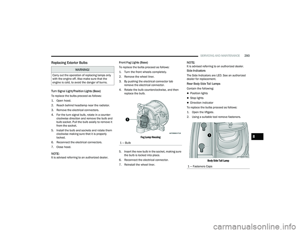
Replacing Exterior Bulbs
Turn Signal Light/Position Lights (Base)
To replace the bulbs proceed as follows:
1. Open hood.
2. Reach behind headlamp near the radiator.
3. Remove the electrical connectors.
4. For the turn signal bulb, rotate in a counter -
clockwise direction and remove the bulb and
bulb socket. Pull the bulb axially to remove it
from the socket.
5. Install the bulb and sockets and rotate them clockwise making sure that it is properly
locked.
6. Reconnect the electrical connectors.
7. Close hood.
NOTE:It is advised referring to an authorized dealer. Front Fog Lights (Base)
To replace the bulbs proceed as follows:
1. Turn the front wheels completely.
2. Remove the wheel liner.
3. By pushing the electrical connector tab
remove the electrical connector.
4. Rotate the bulb counterclockwise, and then replace the bulb.
Fog Lamp Housing
5. Insert the new bulb in the socket, making sure the bulb is locked into place.
6. Reconnect the electrical connector.
7. Reinstall the wheel liner.
NOTE:It is advised referring to an authorized dealer.
Side Indicators
The Side Indicators are LED. See an authorized
dealer for replacement.
Rear Body Side Tail Lamps
Contain the following:
Position lights
Stop lights
Direction indicator
To replace the bulbs proceed as follows:
1. Open the liftgate.
2. Using a suitable tool remove fasteners.
Body Side Tail Lamp
WARNING!
Carry out the operation of replacing lamps only
with the engine off. Also make sure that the
engine is cold, to avoid the danger of burns.
1 — Bulb
1 — Fasteners Caps
8
22_MP_OM_EN_USC_t.book Page 293