tow JEEP COMPASS 2023 Owners Manual
[x] Cancel search | Manufacturer: JEEP, Model Year: 2023, Model line: COMPASS, Model: JEEP COMPASS 2023Pages: 344, PDF Size: 18.8 MB
Page 7 of 344
5
PARKSENSE ACTIVE PARK ASSIST SYSTEM —
IF EQUIPPED ......................................................... 140 Enabling And Disabling The ParkSense
Active Park Assist System ............................. 140
Parallel/Perpendicular Parking Space
Assistance Operation .................................... 141
Exiting The Parking Space ............................ 144
ACTIVE LANE MANAGEMENT SYSTEM —
IF EQUIPPED ........................................................ 145
Active Lane Management Operation ........... 145
Turning Active Lane Management On
Or Off .............................................................. 146
Active Lane Management Warning
Message......................................................... 146
Changing Active Lane Management
Status ............................................................. 148
PARKVIEW REAR BACK UP CAMERA ............... 148
SURROUND VIEW CAMERA SYSTEM —
IF EQUIPPED ......................................................... 150
Zoom View ..................................................... 152
REFUELING THE VEHICLE ................................... 152
VEHICLE LOADING .............................................. 153
Certification Label ......................................... 153 TRAILER TOWING ................................................ 154
Common Towing Definitions......................... 154
Trailer Towing Weights
(Maximum Trailer Weight Ratings) .............. 155Trailer And Tongue Weight............................ 156
Towing Requirements .................................. 156
Towing Tips ................................................... 159
RECREATIONAL TOWING
(BEHIND MOTORHOME) .................................... 160
Towing This Vehicle Behind Another
Vehicle ........................................................... 160
Recreational Towing — Front-Wheel
Drive (FWD) Models ...................................... 160
Recreational Towing — 4X4 Models ............. 161
DRIVING TIPS ....................................................... 161
On-Road Driving Tips..................................... 161
Off-Road Driving Tips .................................... 161
MULTIMEDIA
UCONNECT SYSTEMS ........................................ 164
CYBERSECURITY ................................................ 164
UCONNECT SETTINGS ........................................ 165Customer Programmable Features.............. 165
RADIO OPERATION AND MOBILE PHONES ..... 186
Regulatory And Safety Information .............. 186
SAFETY
SAFETY FEATURES .............................................. 187 Anti-Lock Brake System (ABS) ..................... 187Electronic Brake Control (EBC) System ...... 188
AUXILIARY DRIVING SYSTEMS .......................... 194
Blind Spot Monitoring (BSM) —
If Equipped .................................................... 194
Forward Collision Warning (FCW) With
Mitigation — If Equipped ............................... 198
Tire Pressure Monitoring System (TPMS) .... 201
OCCUPANT RESTRAINT SYSTEMS ................... 204
Occupant Restraint Systems Features ....... 204
Important Safety Precautions ...................... 204
Seat Belt Systems ........................................ 205
Supplemental Restraint Systems (SRS) ...... 213Child Restraints ............................................. 228
SAFETY TIPS ........................................................ 240
Transporting Passengers.............................. 240
Transporting Pets ......................................... 240
Safety Checks You Should Make Inside
The Vehicle ................................................... 241
Periodic Safety Checks You Should
Make Outside The Vehicle ............................ 242
Exhaust Gas................................................... 243
Carbon Monoxide Warnings ......................... 243
22_MP_OM_EN_USC_t.book Page 5
Page 8 of 344
6
IN CASE OF EMERGENCY
HAZARD WARNING FLASHERS ........................ 244
SOS MIRROR — IF EQUIPPED ............................ 244
JACKING AND TIRE CHANGING —
IF EQUIPPED ......................................................... 247
Preparations For Jacking ............................. 248
Jack Location/Spare Tire Stowage .............. 248
Jacking Instructions ..................................... 250
TIRE SERVICE KIT — IF EQUIPPED ..................... 252
JUMP STARTING................................................... 258
Preparations For Jump Start......................... 258Jump Starting Procedure .............................. 259
REFUELING IN EMERGENCY............................... 260
IF YOUR ENGINE OVERHEATS ........................... 261
GEAR SELECTOR OVERRIDE ............................. 262
FREEING A STUCK VEHICLE .............................. 262
TOWING A DISABLED VEHICLE .......................... 264 Without The Key Fob ..................................... 265
Front-Wheel Drive (FWD) Models —
With Key Fob.................................................. 265
4x4 Models .................................................... 265
Emergency Tow Hooks —
If Equipped .................................................... 266 ENHANCED ACCIDENT RESPONSE
SYSTEM (EARS) .................................................. 266
EVENT DATA RECORDER (EDR) ........................ 266
SERVICING AND MAINTENANCE
SCHEDULED SERVICING ................................... 267
Maintenance Plan ......................................... 268
ENGINE COMPARTMENT .................................... 271
2.4L Engine ................................................... 271
Checking Oil Level ......................................... 272
Adding Washer Fluid .................................... 272
Maintenance-Free Battery ............................ 272
Pressure Washing ......................................... 273
VEHICLE MAINTENANCE..................................... 273
Engine Oil ....................................................... 273
Engine Oil Filter ............................................. 274Engine Air Cleaner Filter ............................... 274
Air Conditioner Maintenance........................ 274
Body Lubrication ........................................... 275Wiper Blades ................................................ 275Exhaust System ............................................ 278
Cooling System .............................................. 279
Brake System ............................................... 282
Automatic Transmission —
If Equipped..................................................... 283Fuses.............................................................. 284
Bulb Replacement ........................................ 291 TIRES .................................................................... 298
Tire Safety Information ................................ 298Tires — General Information ........................ 306Tire Types....................................................... 309Spare Tires — If Equipped ............................ 310
Snow Traction Devices ................................. 311
Tire Rotation Recommendations ................ 313
DEPARTMENT OF TRANSPORTATION UNIFORM
TIRE QUALITY GRADES ...................................... 314
Treadwear...................................................... 314
Traction Grades ............................................. 314Temperature Grades..................................... 314
STORING THE VEHICLE ....................................... 315
BODYWORK .......................................................... 315
Protection From Atmospheric Agents .......... 315
Body And Underbody Maintenance ............. 315
Preserving The Bodywork ............................. 316
INTERIORS ........................................................... 317
Seats And Fabric Parts ................................. 317
Plastic And Coated Parts .............................. 318
Leather Surfaces........................................... 318
Glass Surfaces ............................................. 318
22_MP_OM_EN_USC_t.book Page 6
Page 14 of 344
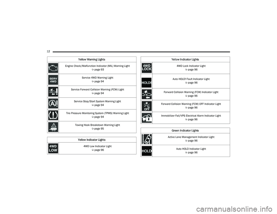
12 Engine Check/Malfunction Indicator (MIL) Warning Light Úpage 93
Service 4WD Warning Light Úpage 94
Service Forward Collision Warning (FCW) Light Úpage 94
Service Stop/Start System Warning Light Úpage 94
Tire Pressure Monitoring System (TPMS) Warning Light Úpage 94
Towing Hook Breakdown Warning Light Úpage 95
Yellow Indicator Lights
4WD Low Indicator Light
Úpage 96
Yellow Warning Lights
4WD Lock Indicator Light
Úpage 96
Auto HOLD! Fault Indicator Light Úpage 96
Forward Collision Warning (FCW) Indicator Light Úpage 96
Forward Collision Warning (FCW) OFF Indicator Light Úpage 96
Immobilizer Fail/VPS Electrical Alarm Indicator Light Úpage 96
Green Indicator Lights
Active Lane Management Indicator Light
Úpage 96
Auto HOLD Indicator Light Úpage 96
Yellow Indicator Lights
22_MP_OM_EN_USC_t.book Page 12
Page 28 of 344
26GETTING TO KNOW YOUR VEHICLE
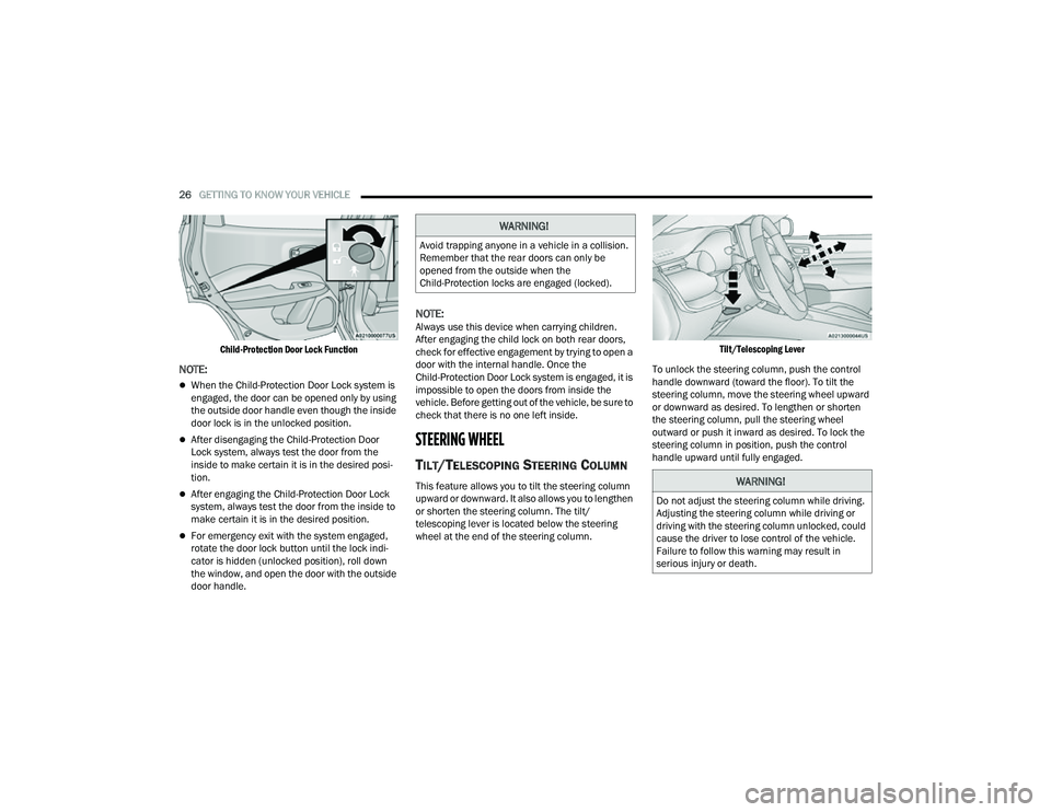
Child-Protection Door Lock Function
NOTE:
When the Child-Protection Door Lock system is
engaged, the door can be opened only by using
the outside door handle even though the inside
door lock is in the unlocked position.
After disengaging the Child-Protection Door
Lock system, always test the door from the
inside to make certain it is in the desired posi -
tion.
After engaging the Child-Protection Door Lock
system, always test the door from the inside to
make certain it is in the desired position.
For emergency exit with the system engaged,
rotate the door lock button until the lock indi -
cator is hidden (unlocked position), roll down
the window, and open the door with the outside
door handle.
NOTE:Always use this device when carrying children.
After engaging the child lock on both rear doors,
check for effective engagement by trying to open a
door with the internal handle. Once the
Child-Protection Door Lock system is engaged, it is
impossible to open the doors from inside the
vehicle. Before getting out of the vehicle, be sure to
check that there is no one left inside.
STEERING WHEEL
TILT/TELESCOPING STEERING COLUMN
This feature allows you to tilt the steering column
upward or downward. It also allows you to lengthen
or shorten the steering column. The tilt/
telescoping lever is located below the steering
wheel at the end of the steering column.
Tilt/Telescoping Lever
To unlock the steering column, push the control
handle downward (toward the floor). To tilt the
steering column, move the steering wheel upward
or downward as desired. To lengthen or shorten
the steering column, pull the steering wheel
outward or push it inward as desired. To lock the
steering column in position, push the control
handle upward until fully engaged.
WARNING!
Avoid trapping anyone in a vehicle in a collision.
Remember that the rear doors can only be
opened from the outside when the
Child-Protection locks are engaged (locked).
WARNING!
Do not adjust the steering column while driving.
Adjusting the steering column while driving or
driving with the steering column unlocked, could
cause the driver to lose control of the vehicle.
Failure to follow this warning may result in
serious injury or death.
22_MP_OM_EN_USC_t.book Page 26
Page 37 of 344
GETTING TO KNOW YOUR VEHICLE35
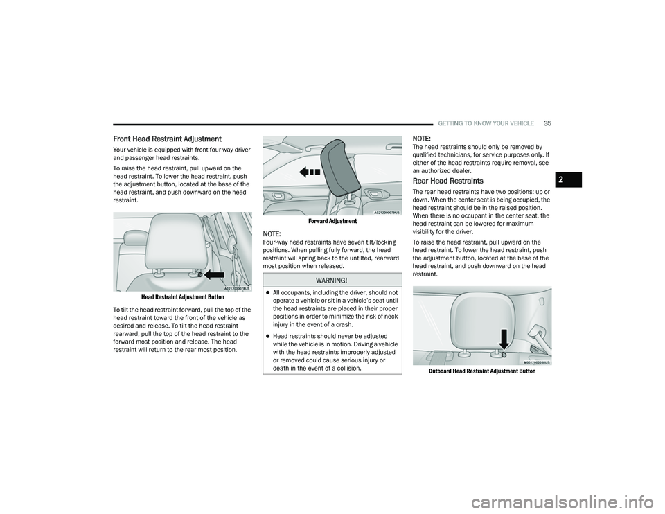
Front Head Restraint Adjustment
Your vehicle is equipped with front four way driver
and passenger head restraints.
To raise the head restraint, pull upward on the
head restraint. To lower the head restraint, push
the adjustment button, located at the base of the
head restraint, and push downward on the head
restraint.
Head Restraint Adjustment Button
To tilt the head restraint forward, pull the top of the
head restraint toward the front of the vehicle as
desired and release. To tilt the head restraint
rearward, pull the top of the head restraint to the
forward most position and release. The head
restraint will return to the rear most position.
Forward Adjustment
NOTE:Four-way head restraints have seven tilt/locking
positions. When pulling fully forward, the head
restraint will spring back to the untilted, rearward
most position when released.
NOTE:The head restraints should only be removed by
qualified technicians, for service purposes only. If
either of the head restraints require removal, see
an authorized dealer.
Rear Head Restraints
The rear head restraints have two positions: up or
down. When the center seat is being occupied, the
head restraint should be in the raised position.
When there is no occupant in the center seat, the
head restraint can be lowered for maximum
visibility for the driver.
To raise the head restraint, pull upward on the
head restraint. To lower the head restraint, push
the adjustment button, located at the base of the
head restraint, and push downward on the head
restraint.
Outboard Head Restraint Adjustment Button
WARNING!
All occupants, including the driver, should not
operate a vehicle or sit in a vehicle’s seat until
the head restraints are placed in their proper
positions in order to minimize the risk of neck
injury in the event of a crash.
Head restraints should never be adjusted
while the vehicle is in motion. Driving a vehicle
with the head restraints improperly adjusted
or removed could cause serious injury or
death in the event of a collision.
2
22_MP_OM_EN_USC_t.book Page 35
Page 39 of 344
GETTING TO KNOW YOUR VEHICLE37
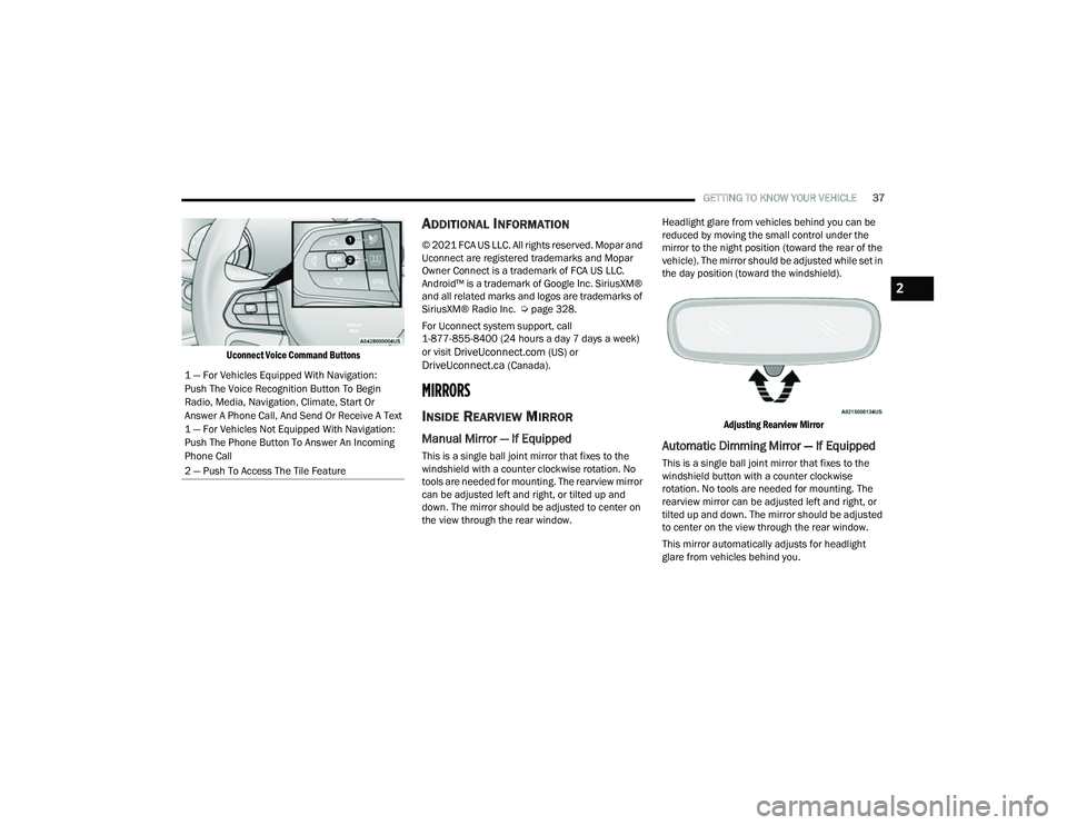
Uconnect Voice Command Buttons
ADDITIONAL INFORMATION
© 2021 FCA US LLC. All rights reserved. Mopar and
Uconnect are registered trademarks and Mopar
Owner Connect is a trademark of FCA US LLC.
Android™ is a trademark of Google Inc. SiriusXM®
and all related marks and logos are trademarks of
SiriusXM® Radio Inc. Ú page 328.
For Uconnect system support, call
1-877-855-8400 (24 hours a day 7 days a week)
or visit
DriveUconnect.com (US) or DriveUconnect.ca (Canada).
MIRRORS
INSIDE REARVIEW MIRROR
Manual Mirror — If Equipped
This is a single ball joint mirror that fixes to the
windshield with a counter clockwise rotation. No
tools are needed for mounting. The rearview mirror
can be adjusted left and right, or tilted up and
down. The mirror should be adjusted to center on
the view through the rear window. Headlight glare from vehicles behind you can be
reduced by moving the small control under the
mirror to the night position (toward the rear of the
vehicle). The mirror should be adjusted while set in
the day position (toward the windshield).
Adjusting Rearview Mirror
Automatic Dimming Mirror — If Equipped
This is a single ball joint mirror that fixes to the
windshield button with a counter clockwise
rotation. No tools are needed for mounting. The
rearview mirror can be adjusted left and right, or
tilted up and down. The mirror should be adjusted
to center on the view through the rear window.
This mirror automatically adjusts for headlight
glare from vehicles behind you.
1 — For Vehicles Equipped With Navigation:
Push The Voice Recognition Button To Begin
Radio, Media, Navigation, Climate, Start Or
Answer A Phone Call, And Send Or Receive A Text
1 — For Vehicles Not Equipped With Navigation:
Push The Phone Button To Answer An Incoming
Phone Call
2 — Push To Access The Tile Feature
2
22_MP_OM_EN_USC_t.book Page 37
Page 40 of 344
38GETTING TO KNOW YOUR VEHICLE
NOTE:The Automatic Dimming Mirror feature is disabled
when the vehicle is in REVERSE to improve the
driver’s rear view. If your vehicle is equipped with
an on/off button on the mirror, the mirror will
default to on and can be turned on/off through the
touchscreen.
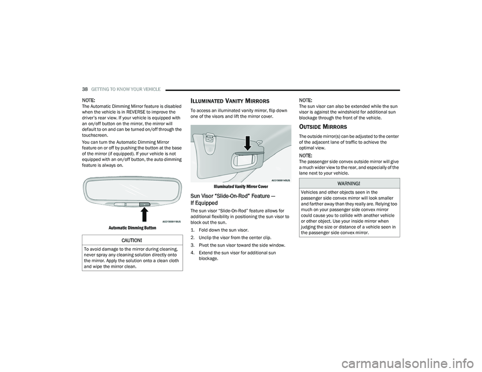
You can turn the Automatic Dimming Mirror
feature on or off by pushing the button at the base
of the mirror (if equipped). If your vehicle is not
equipped with an on/off button, the auto dimming
feature is always on.
Automatic Dimming Button
ILLUMINATED VANITY MIRRORS
To access an illuminated vanity mirror, flip down
one of the visors and lift the mirror cover.
Illuminated Vanity Mirror Cover
Sun Visor “Slide-On-Rod” Feature —
If Equipped
The sun visor “Slide-On-Rod” feature allows for
additional flexibility in positioning the sun visor to
block out the sun.
1. Fold down the sun visor.
2. Unclip the visor from the center clip.
3. Pivot the sun visor toward the side window.
4. Extend the sun visor for additional sun blockage.
NOTE:The sun visor can also be extended while the sun
visor is against the windshield for additional sun
blockage through the front of the vehicle.
OUTSIDE MIRRORS
The outside mirror(s) can be adjusted to the center
of the adjacent lane of traffic to achieve the
optimal view.
NOTE:The passenger side convex outside mirror will give
a much wider view to the rear, and especially of the
lane next to your vehicle.
CAUTION!
To avoid damage to the mirror during cleaning,
never spray any cleaning solution directly onto
the mirror. Apply the solution onto a clean cloth
and wipe the mirror clean.
WARNING!
Vehicles and other objects seen in the
passenger side convex mirror will look smaller
and farther away than they really are. Relying too
much on your passenger side convex mirror
could cause you to collide with another vehicle
or other object. Use your inside mirror when
judging the size or distance of a vehicle seen in
the passenger side convex mirror.
22_MP_OM_EN_USC_t.book Page 38
Page 46 of 344
44GETTING TO KNOW YOUR VEHICLE
HEADLIGHT SWITCH
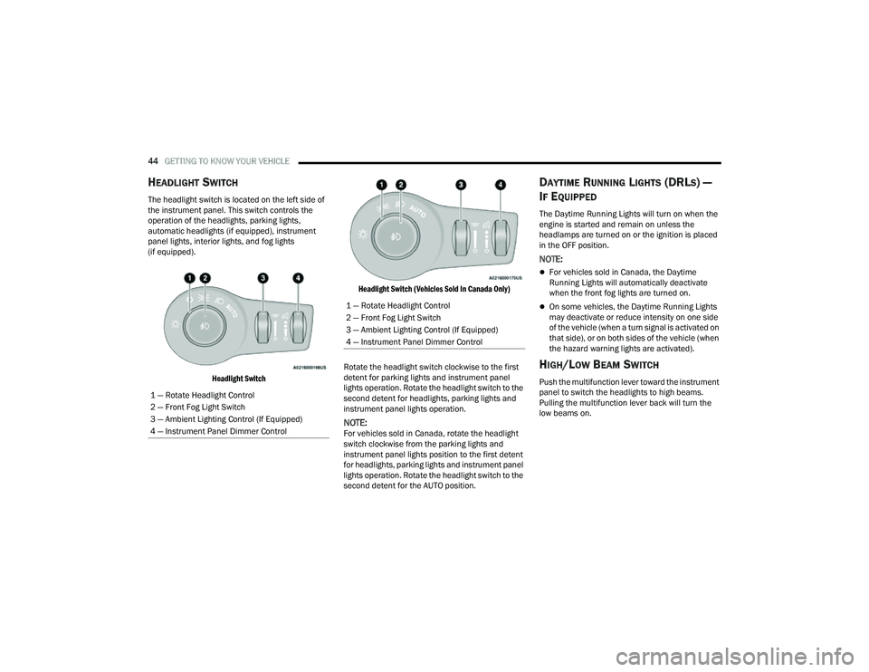
The headlight switch is located on the left side of
the instrument panel. This switch controls the
operation of the headlights, parking lights,
automatic headlights (if equipped), instrument
panel lights, interior lights, and fog lights
(if equipped).
Headlight Switch Headlight Switch (Vehicles Sold In Canada Only)
Rotate the headlight switch clockwise to the first
detent for parking lights and instrument panel
lights operation. Rotate the headlight switch to the
second detent for headlights, parking lights and
instrument panel lights operation.
NOTE:For vehicles sold in Canada, rotate the headlight
switch clockwise from the parking lights and
instrument panel lights position to the first detent
for headlights, parking lights and instrument panel
lights operation. Rotate the headlight switch to the
second detent for the AUTO position.
DAYTIME RUNNING LIGHTS (DRLS) —
I
F EQUIPPED
The Daytime Running Lights will turn on when the
engine is started and remain on unless the
headlamps are turned on or the ignition is placed
in the OFF position.
NOTE:
For vehicles sold in Canada, the Daytime
Running Lights will automatically deactivate
when the front fog lights are turned on.
On some vehicles, the Daytime Running Lights
may deactivate or reduce intensity on one side
of the vehicle (when a turn signal is activated on
that side), or on both sides of the vehicle (when
the hazard warning lights are activated).
HIGH/LOW BEAM SWITCH
Push the multifunction lever toward the instrument
panel to switch the headlights to high beams.
Pulling the multifunction lever back will turn the
low beams on.
1 — Rotate Headlight Control
2 — Front Fog Light Switch
3 — Ambient Lighting Control (If Equipped)
4 — Instrument Panel Dimmer Control
1 — Rotate Headlight Control
2 — Front Fog Light Switch
3 — Ambient Lighting Control (If Equipped)
4 — Instrument Panel Dimmer Control
22_MP_OM_EN_USC_t.book Page 44
Page 47 of 344
GETTING TO KNOW YOUR VEHICLE45
AUTOMATIC HIGH BEAM HEADLAMP
C
ONTROL — IF EQUIPPED
The Automatic High Beam Headlamp Control
system provides increased forward lighting at night
by automating high beam control through the use
of a digital camera mounted on the windshield.
This camera detects vehicle specific light and
automatically switches from high beams to low
beams until the approaching vehicle is out of view.
NOTE:
The Automatic High Beam Headlamp Control
can be turned on or off through Uconnect
Settings Ú page 165.
Broken, muddy, or obstructed headlights and
taillights of vehicles in the field of view will
cause headlights to remain on longer (closer to
the vehicle). Also, dirt, film, and other obstruc -
tions on the windshield or camera lens will
cause the system to function improperly.
FLASH-TO-PASS
You can signal another vehicle with your headlights
by lightly pulling the multifunction lever toward you.
This will cause the high beam headlights to turn on,
and remain on, until the lever is released.
AUTOMATIC HEADLIGHTS — IF EQUIPPED
This system automatically turns the headlights on
or off according to ambient light levels. To turn the
system on, rotate the headlight switch clockwise to
the last detent for automatic headlight operation.
When the system is on, the headlight time delay
feature is also on. This means the headlights will
stay on for up to 90 seconds after you place the
ignition into the OFF position. To turn the
automatic system off, move the headlight switch
out of the AUTO position.
NOTE:The engine must be running before the headlights
will come on in the automatic mode.
HEADLIGHT TIME DELAY
To assist when exiting the vehicle, the headlight
delay feature will leave the headlights on for up to
90 seconds.
To activate the delay feature, place the ignition in
the OFF position while the headlights are still on.
Then, turn off the headlights within 45 seconds.
The delay interval begins when the headlight
switch is turned off. Headlight delay can be cancelled by either turning
the headlights or parking lights on, or placing the
ignition in the ON/RUN position.
If you turn the headlights off before the ignition,
they will turn off in the normal manner.
NOTE:
The lights must be turned off within 45 seconds
of placing the ignition in the OFF position to acti
-
vate this feature. If the headlight switch is in the
AUTO position prior to placing the ignition in the
OFF position, there is no need to turn the head-
light switch to off to activate Headlight Delay.
The headlight delay timing is programmable
through Uconnect Settings Ú page 165.
LIGHTS-ON REMINDER
If the headlights or parking lights are on after the
ignition is in the OFF position, a chime will sound to
alert the driver when the driver's door is opened.
2
22_MP_OM_EN_USC_t.book Page 45
Page 50 of 344
48GETTING TO KNOW YOUR VEHICLE
Ambient Light Dimmer (Vehicles Sold In Canada Only)
WINDSHIELD WIPERS AND WASHERS
The windshield wiper/washer controls are located
on the windshield wiper/washer lever on the right
side of the steering column. The front wipers are
operated by rotating a switch, located on the end of
the lever. For information on the rear wiper/
washer, see Ú page 49.
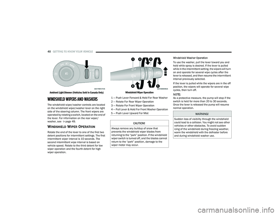
WINDSHIELD WIPER OPERATION
Rotate the end of the lever to one of the first two
detent positions for intermittent settings. The first
intermittent wiper interval is 10 seconds. The
second intermittent wipe interval is based on
vehicle speed. Rotate to the third detent for low
wiper operation and the fourth detent for high
wiper operation.
Windshield Wiper Operation
Windshield Washer Operation
To use the washer, pull the lever toward you and
hold while spray is desired. If the lever is pulled
while in the intermittent setting, the wipers will turn
on and operate for several wipe cycles after the
lever is released, and then resume the intermittent
interval previously selected.
If the lever is pulled while the wipers are in the off
position, the wipers will operate for several wipe
cycles, then turn off.
NOTE:As a protective measure, the pump will stop if the
switch is held for more than 20 to 30 seconds.
Once the lever is released the pump will resume
normal operation.1 — Push Lever Forward & Hold For Rear Washer
2 — Rotate For Rear Wiper Operation
3 — Rotate For Front Wiper Operation
4 — Pull Lever & Hold For Front Washer Operation
5 — Push Lever Upward For Mist
CAUTION!
Always remove any buildup of snow that
prevents the windshield wiper blades from
returning to the “park” position. If the windshield
wiper switch is turned off, and the blades cannot
return to the “park” position, damage to the
wiper motor may occur.
WARNING!
Sudden loss of visibility through the windshield
could lead to a collision. You might not see other
vehicles or other obstacles. To avoid sudden
icing of the windshield during freezing weather,
warm the windshield with the defroster before
and during windshield washer use.
22_MP_OM_EN_USC_t.book Page 48