tow bar JEEP COMPASS 2023 Owners Manual
[x] Cancel search | Manufacturer: JEEP, Model Year: 2023, Model line: COMPASS, Model: JEEP COMPASS 2023Pages: 344, PDF Size: 18.8 MB
Page 54 of 344
52GETTING TO KNOW YOUR VEHICLE
Driver And Passenger Temperature
Control Buttons
These buttons provide the driver and passenger
with independent temperature control.
Push the red button on the faceplate or
touchscreen or press and slide the
temperature bar towards the red arrow
button on the touchscreen for warmer
temperature settings. Push the blue button on the faceplate or
touchscreen or press and slide the
temperature bar towards the blue arrow
button on the touchscreen for cooler
temperature settings.
SYNC Button
Press the SYNC button on the
touchscreen to toggle the Sync feature
on/off. The SYNC indicator is illuminated
when SYNC is on. SYNC is used to
synchronize the passenger temperature setting
with the driver temperature setting. Changing the
passenger temperature setting while in SYNC will
automatically exit this feature.
NOTE:The SYNC button is only available on the touch-
screen.
Blower Control
Blower Control is used to regulate the
amount of air forced through the Climate
Control system. There are seven blower
speeds available. Adjusting the blower
will cause automatic mode to switch to manual
operation. The speeds can be selected using either
the blower control knob on the faceplate or the
buttons on the touchscreen. Faceplate
The blower speed increases as you turn the blower
control knob clockwise from the lowest blower
setting. The blower speed decreases as you turn
the blower control knob counterclockwise.
Touchscreen
Use the small blower icon to reduce the blower
setting and the large blower icon to increase the
blower setting. Blower can also be selected by
pressing the blower bar area between the icons.
Mode Control
Mode Control regulates the airflow
distribution. The airflow distribution
outlets are: instrument panel outlets,
floor outlets, defrost outlets, and
demist outlets.
Faceplate
Push the Mode button to change the airflow
distribution mode.
Touchscreen
Press one of the “MODE” buttons to change the
airflow distribution mode.
CAUTION!
Failure to follow these cautions can cause
damage to the heating elements:
Use care when washing the inside of the rear
window. Do not use abrasive window cleaners
on the interior surface of the window. Use a
soft cloth and a mild washing solution, wiping
parallel to the heating elements. Labels can
be peeled off after soaking with warm water.
Do not use scrapers, sharp instruments, or
abrasive window cleaners on the interior
surface of the window.
Keep all objects a safe distance from the
window.
22_MP_OM_EN_USC_t.book Page 52
Page 57 of 344
GETTING TO KNOW YOUR VEHICLE55
Temperature Control
Temperature Control regulates the temperature of
the air forced through the climate system.
Push the red button on the faceplate or
touchscreen or press and slide the
temperature bar towards the red arrow
button on the touchscreen for warmer
temperature settings.
Push the blue button on the faceplate or
touchscreen or press and slide the
temperature bar towards the blue arrow
button on the touchscreen for cooler
temperature settings.
Blower Control
Blower Control is used to regulate the
amount of air forced through the Climate
Control system. There are seven blower
speeds available. Adjusting the blower
will cause automatic mode to switch to manual
operation. The speeds can be selected using either
the blower control knob on the faceplate or the
buttons on the touchscreen.
Faceplate
The blower speed increases as you turn the blower
control knob clockwise from the lowest blower
setting. The blower speed decreases as you turn
the blower control knob counterclockwise. Touchscreen
Use the small blower icon to reduce the blower
setting and the large blower icon to increase the
blower setting. Blower can also be selected by
pressing the blower bar area between the icons.
Mode Control
Push the Mode Control button to change
the airflow distribution mode. The airflow
distribution mode can be adjusted so air
comes from the instrument panel
outlets, floor outlets, defrost outlets and demist
outlets.
Panel Mode
Air comes from the outlets in the
instrument panel. Each of these outlets
can be individually adjusted to direct the
flow of air. The air vanes of the center
outlets and outboard outlets can be moved up and
down or side to side to regulate airflow direction.
There is a shut-off wheel located below the air
vanes to shut off or adjust the amount of airflow
from these outlets.
Bi-Level Mode
Air comes from the instrument panel
outlets and floor outlets. A slight amount
of air is directed through the defrost and
side window demister outlets.
NOTE:Bi-Level mode is designed under comfort condi -
tions to provide cooler air out of the panel outlets
and warmer air from the floor outlets.
Floor Mode
Air comes from the floor outlets. A slight
amount of air is directed through the
defrost and side window demister
outlets.
Defrost Mode
Air comes from the windshield and side
window demist outlets. When the defrost
button is selected, the blower level may
increase. Use Defrost mode with
maximum temperature settings for best
windshield and side window defrosting and
defogging. When toggling the front defrost mode
button, the Climate Control system will return to
the previous setting.
Mix Mode
Air is directed through the floor, defrost,
and side window demister outlets. This
setting works best in cold or snowy
conditions that require extra heat to the
windshield. This setting is good for maintaining
comfort while reducing moisture on the
windshield.
2
22_MP_OM_EN_USC_t.book Page 55
Page 157 of 344
STARTING AND OPERATING155
Trailer Sway Control (TSC)
The TSC can be a mechanical telescoping link that
can be installed between the hitch receiver and the
trailer tongue that typically provides adjustable
friction associated with the telescoping motion to
dampen any unwanted trailer swaying motions
while traveling.
If equipped, the electronic TSC recognizes a
swaying trailer and automatically applies individual
wheel brakes and/or reduces engine power to
attempt to eliminate the trailer sway.
Weight-Carrying Hitch
A weight-carrying hitch supports the trailer tongue
weight, just as if it were luggage located at a hitch
ball or some other connecting point of the vehicle. These kinds of hitches are commonly used to tow
small and medium sized trailers.
Weight-Distributing Hitch
A Weight-Distributing system works by applying
leverage through spring (load) bars. They are
typically used for heavier loads to distribute trailer
tongue weight to the tow vehicle's front axle and
the trailer axle(s). When used in accordance with
the manufacturer's directions, it provides for a
more level ride, offering more consistent steering
and brake control thereby enhancing towing
safety. The addition of a friction/hydraulic sway
control also dampens sway caused by traffic and
crosswinds and contributes positively to tow
vehicle and trailer stability. Trailer sway control and
a Weight-Distributing (load equalizing) Hitch are recommended for heavier Tongue Weights (TW)
and may be required depending on vehicle and
trailer configuration/loading to comply with Gross
Axle Weight Rating (GAWR) requirements.
TRAILER TOWING WEIGHTS (MAXIMUM TRAILER WEIGHT RATINGS)
WARNING!
An improperly adjusted Weight-Distributing
Hitch system may reduce handling, stability,
braking performance, and could result in a
collision.
Weight-Distributing systems may not be
compatible with surge brake couplers. Consult
with your hitch and trailer manufacturer or a
reputable Recreational Vehicle dealer for
additional information.
Engine/Transmission
ModelMaximum GTW Maximum Trailer TW
2.4L / 6 Speed Auto FWDTrailer towing is not recommended.
2.4L / 9 Speed Auto FWD or 4WD2,000 lb (907 kg) 200 lb (90 kg)
When towing a trailer, the technically permissible laden weight may be exceeded by not more than 10% or 220 lb (100 kg), whichever is lower provided that the operating speed is restricted to 62 mph (100 km/h) or less.
Refer to local laws for maximum trailer towing speeds and loads.
Towing limits quoted represent the maximum towing ability of the vehicle at its Gross Combined Mass to restart on a 12 percent gradient at sea level. The performance and economy of all models will be reduced when used for towing.
4
22_MP_OM_EN_USC_t.book Page 155
Page 163 of 344
STARTING AND OPERATING161
RECREATIONAL TOWING — 4X4
M
ODELS
Recreational towing (with all four wheels on the
ground, or using a towing dolly) is NOT ALLOWED.
This vehicle may be towed on flatbed or vehicle
trailer provided all four wheels are OFF the ground.
DRIVING TIPS
ON-ROAD DRIVING TIPS
Utility vehicles have higher ground clearance and a
narrower track to make them capable of
performing in a wide variety of off-road
applications. Specific design characteristics give
them a higher center of gravity than conventional
passenger cars.
An advantage of the higher ground clearance is a
better view of the road, allowing you to anticipate
problems. They are not designed for cornering at
the same speeds as conventional passenger cars
any more than low-slung sports cars are designed
to perform satisfactorily in off-road conditions.
Avoid sharp turns or abrupt maneuvers. As with
other vehicles of this type, failure to operate this
vehicle correctly may result in loss of control or
vehicle rollover.
OFF-ROAD DRIVING TIPS
When To Use 4WD LOW Range
When off-road driving, shift to 4WD LOW for
additional traction and control on slippery or
difficult terrain, ascending or descending steep
hills, and to increase low-speed pulling power
Ú page 112. This range should be limited to extreme situations such as deep snow, mud, or
sand where additional low speed pulling power is
needed. Vehicle speeds in excess of 25 mph
(40 km/h) should be avoided when in 4WD LOW
range.
Driving Through Water
Although your vehicle is capable of driving through
water, there are a number of precautions that
must be considered before entering the water:
Driving through water more than a few inches/
centimeters deep will require extra caution to
ensure safety and prevent damage to your vehicle.
If you must drive through water, try to determine
the depth and the bottom condition (and location
of any obstacles) prior to entering. Proceed with
caution and maintain a steady controlled speed
less than 5 mph (8 km/h) in deep water to
minimize wave effects.
CAUTION!
Towing with the front wheels on the ground
will cause severe transmission damage.
Damage from improper towing is not covered
under the New Vehicle Limited Warranty.
Ensure that the Electric Park Brake is
released, and remains released, while being
towed.
Do not use a bumper mounted clamp-on tow
bar on your vehicle. The fascia/bumper face
will be damaged.
CAUTION!
Towing this vehicle with ANY of its wheels on the
ground can cause severe transmission and/or
power transfer unit damage. Damage from
improper towing is not covered under the
New Vehicle Limited Warranty.
CAUTION!
When driving through water, do not exceed
5 mph (8 km/h). Always check water depth
before entering as a precaution, and check all
fluids afterward. Driving through water may
cause damage that may not be covered by the
New Vehicle Limited Warranty.
4
22_MP_OM_EN_USC_t.book Page 161
Page 266 of 344
264IN CASE OF EMERGENCY
TOWING A DISABLED VEHICLE
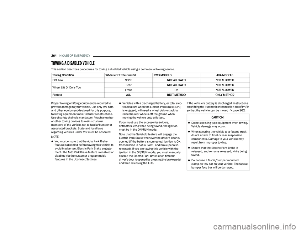
This section describes procedures for towing a disabled vehicle using a commercial towing service.
Proper towing or lifting equipment is required to
prevent damage to your vehicle. Use only tow bars
and other equipment designed for this purpose,
following equipment manufacturer’s instructions.
Use of safety chains is mandatory. Attach a tow bar
or other towing devices to main structural
members of the vehicle, not to fascia/bumper or
associated brackets. State and local laws
regarding vehicles under tow must be observed.
NOTE:
You must ensure that the Auto Park Brake
feature is disabled before towing this vehicle to
avoid inadvertent Electric Park Brake engage -
ment. The Auto Park Brake feature is enabled or
disabled via the customer programmable
features in the Uconnect Settings.
Vehicles with a discharged battery, or total elec -
trical failure when the Electric Park Brake (EPB)
is engaged, will need a wheel dolly or jack to
raise the rear wheels off the ground when
moving the vehicle onto a flatbed.
If you must use the accessories (wipers,
defrosters, etc.) while being towed, the ignition
must be in the ON/RUN mode.
Note that the Safehold feature will engage the
Electric Park Brake whenever the driver's door is
opened (if the battery is connected, ignition is ON,
transmission is not in PARK, and brake pedal is
released). If you are towing this vehicle with the
ignition in the ON/RUN mode, you must manually
disable the Electric Park Brake each time the
driver's door is opened by pressing the brake pedal
and then releasing the EPB. If the vehicle’s battery is discharged, instructions
on shifting the automatic transmission out of PARK
so that the vehicle can be moved Ú
page 262.
Towing Condition
Wheels OFF The GroundFWD MODELS 4X4 MODELS
Flat Tow NONENOT ALLOWED NOT ALLOWED
Wheel Lift Or Dolly Tow Rear
NOT ALLOWED NOT ALLOWED
Front OKNOT ALLOWED
Flatbed ALLBEST METHOD ONLY METHOD
CAUTION!
Do not use sling-type equipment when towing.
Vehicle damage may occur.
When securing the vehicle to a flatbed truck,
do not attach to front or rear suspension
components. Damage to your vehicle may
result from improper towing.
Ensure that the Electric Park Brake is
released, and remains released, while being
towed.
Do not use a fascia/bumper mounted
clamp-on tow bar on your vehicle. The fascia/
bumper face bar will be damaged.
22_MP_OM_EN_USC_t.book Page 264
Page 267 of 344
IN CASE OF EMERGENCY265
(Continued)
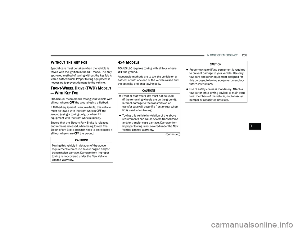
WITHOUT THE KEY FOB
Special care must be taken when the vehicle is
towed with the ignition in the OFF mode. The only
approved method of towing without the key fob is
with a flatbed truck. Proper towing equipment is
necessary to prevent damage to the vehicle.
FRONT-WHEEL DRIVE (FWD) MODELS
— W
ITH KEY FOB
FCA US LLC recommends towing your vehicle with
all four wheels OFF the ground using a flatbed.
If flatbed equipment is not available, this vehicle
must be towed with the front wheels OFF the
ground (using a towing dolly, or wheel lift
equipment with the front wheels raised).
Ensure that the Electric Park Brake is released,
and remains released, while being towed. The
Electric Park Brake does not need to be released if
all four wheels are OFF the ground.
4X4 MODELS
FCA US LLC requires towing with all four wheels
OFF the ground.
Acceptable methods are to tow the vehicle on a
flatbed, or with one end of the vehicle raised and
the opposite end on a towing dolly.
CAUTION!
Towing this vehicle in violation of the above
requirements can cause severe engine and/or
transmission damage. Damage from improper
towing is not covered under the New Vehicle
Limited Warranty.
CAUTION!
Front or rear wheel lifts must not be used
(if the remaining wheels are on the ground).
Internal damage to the transmission or
transfer case will occur if a front or rear wheel
lift is used when towing.
Towing this vehicle in violation of the above
requirements can cause severe transmission
and/or transfer case damage. Damage from
improper towing is not covered under the New
Vehicle Limited Warranty.
Proper towing or lifting equipment is required
to prevent damage to your vehicle. Use only
tow bars and other equipment designed for
this purpose, following equipment manufac -
turer's instructions.
Use of safety chains is mandatory. Attach a
tow bar or other towing devices to main struc -
tural members of the vehicle, not to fascia/
bumper or associated brackets.
CAUTION!
7
22_MP_OM_EN_USC_t.book Page 265
Page 292 of 344
290SERVICING AND MAINTENANCE
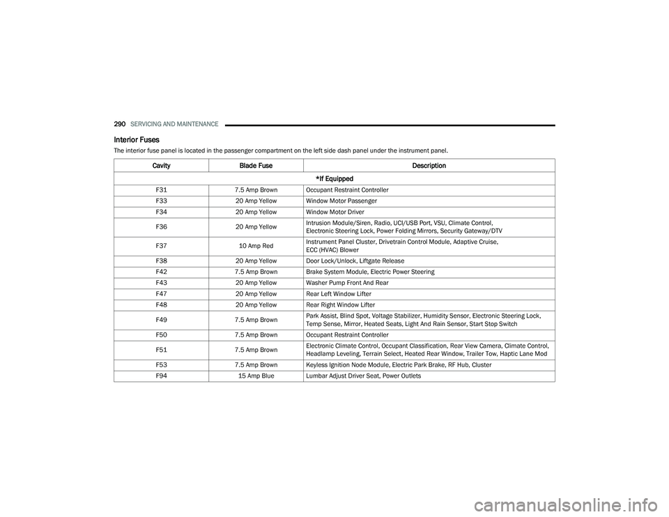
Interior Fuses
The interior fuse panel is located in the passenger compartment on the left side dash panel under the instrument panel.
CavityBlade Fuse Description
*If Equipped
F31 7.5 Amp Brown Occupant Restraint Controller
F33 20 Amp Yellow Window Motor Passenger
F34 20 Amp Yellow Window Motor Driver
F36 20 Amp YellowIntrusion Module/Siren, Radio, UCI/USB Port, VSU, Climate Control,
Electronic Steering Lock, Power Folding Mirrors, Security Gateway/DTV
F37 10 Amp RedInstrument Panel Cluster, Drivetrain Control Module, Adaptive Cruise,
ECC (HVAC) Blower
F38 20 Amp Yellow Door Lock/Unlock, Liftgate Release
F42 7.5 Amp Brown Brake System Module, Electric Power Steering
F43 20 Amp Yellow Washer Pump Front And Rear
F47 20 Amp Yellow Rear Left Window Lifter
F48 20 Amp Yellow Rear Right Window Lifter
F49 7.5 Amp BrownPark Assist, Blind Spot, Voltage Stabilizer, Humidity Sensor, Electronic Steering Lock,
Temp Sense, Mirror, Heated Seats, Light And Rain Sensor, Start Stop Switch
F50 7.5 Amp Brown Occupant Restraint Controller
F51 7.5 Amp BrownElectronic Climate Control, Occupant Classification, Rear View Camera, Climate Control,
Headlamp Leveling, Terrain Select, Heated Rear Window, Trailer Tow, Haptic Lane Mod
F53 7.5 Amp Brown Keyless Ignition Node Module, Electric Park Brake, RF Hub, Cluster
F94 15 Amp Blue Lumbar Adjust Driver Seat, Power Outlets
22_MP_OM_EN_USC_t.book Page 290