JEEP COMPASS LATITUDE 2018 Owners Manual
COMPASS LATITUDE 2018
JEEP
JEEP
https://www.carmanualsonline.info/img/16/56038/w960_56038-0.png
JEEP COMPASS LATITUDE 2018 Owners Manual
Trending: remove seats, antenna, steering wheel, fuse, park assist, tire pressure, bolt pattern
Page 131 of 518
Page 132 of 518
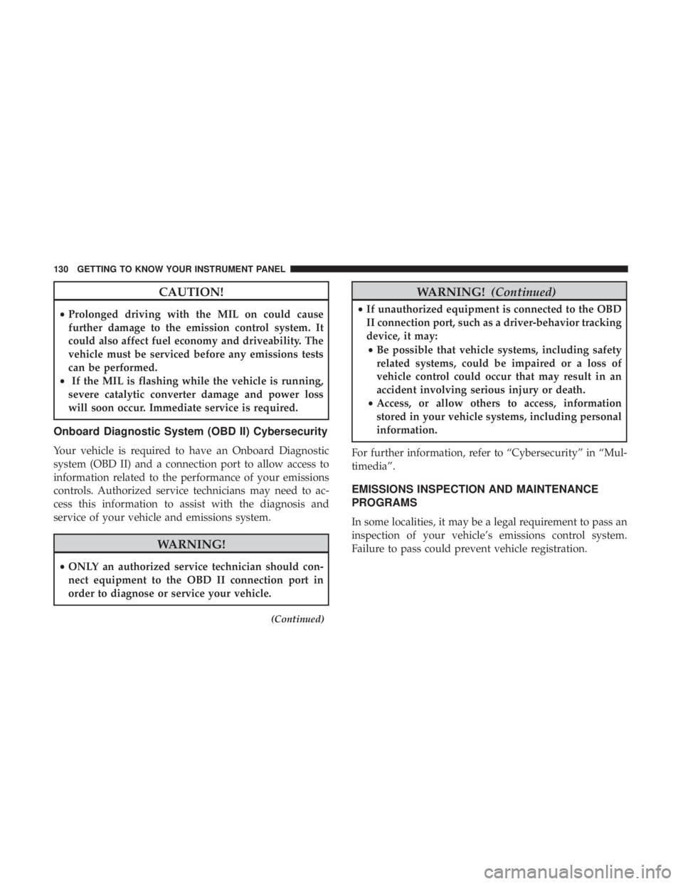
CAUTION!
•Prolonged driving with the MIL on could cause
further damage to the emission control system. It
could also affect fuel economy and driveability. The
vehicle must be serviced before any emissions tests
can be performed.
• If the MIL is flashing while the vehicle is running,
severe catalytic converter damage and power loss
will soon occur. Immediate service is required.
Onboard Diagnostic System (OBD II) Cybersecurity
Your vehicle is required to have an Onboard Diagnostic
system (OBD II) and a connection port to allow access to
information related to the performance of your emissions
controls. Authorized service technicians may need to ac-
cess this information to assist with the diagnosis and
service of your vehicle and emissions system.
Page 133 of 518
4
GETTING TO KNOW YOUR INSTRUMENT PANEL 131
Page 134 of 518
Page 135 of 518
Page 136 of 518
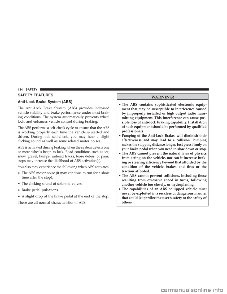
SAFETY FEATURES
Anti-Lock Brake System (ABS)
The Anti-Lock Brake System (ABS) provides increased
vehicle stability and brake performance under most brak-
ing conditions. The system automatically prevents wheel
lock, and enhances vehicle control during braking.
The ABS performs a self-check cycle to ensure that the ABS
is working properly each time the vehicle is started and
driven. During this self-check, you may hear a slight
clicking sound as well as some related motor noises.
ABS is activated during braking when the system detects one
or more wheels begin to lock. Road conditions such as ice,
snow, gravel, bumps, railroad tracks, loose debris, or panic
stops may increase the likelihood of ABS activation(s).
You also may experience the following when ABS activates:
•The ABS motor noise (it may continue to run for a short
time after the stop).
• The clicking sound of solenoid valves.
• Brake pedal pulsations.
• A slight drop of the brake pedal at the end of the stop.
These are all normal characteristics of ABS.
Page 137 of 518
Page 138 of 518
Brake Assist System (BAS)
The BAS is designed to optimize the vehicle’s braking
capability during emergency braking maneuvers. The sys-
tem detects an emergency braking situation by sensing the
rate and amount of brake application and then applies
optimum pressure to the brakes. This can help reduce
braking distances. The BAS complements the anti-lock
brake system (ABS). Applying the brakes very quickly
results in the best BAS assistance. To receive the benefit of
the system, you must apply continuous braking pressure
during the stopping sequence, (do not “pump” the brakes).
Do not reduce brake pedal pressure unless braking is no
longer desired. Once the brake pedal is released, the BAS is
deactivated.
Page 139 of 518
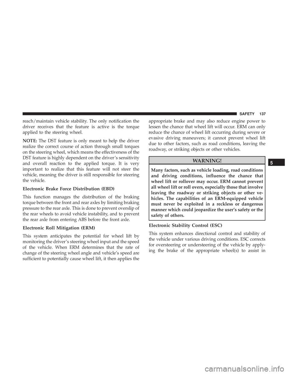
reach/maintain vehicle stability. The only notification the
driver receives that the feature is active is the torque
applied to the steering wheel.
NOTE:The DST feature is only meant to help the driver
realize the correct course of action through small torques
on the steering wheel, which means the effectiveness of the
DST feature is highly dependent on the driver ’s sensitivity
and overall reaction to the applied torque. It is very
important to realize that this feature will not steer the
vehicle, meaning the driver is still responsible for steering
the vehicle.
Electronic Brake Force Distribution (EBD)
This function manages the distribution of the braking
torque between the front and rear axles by limiting braking
pressure to the rear axle. This is done to prevent overslip of
the rear wheels to avoid vehicle instability, and to prevent
the rear axle from entering ABS before the front axle.
Electronic Roll Mitigation (ERM)
This system anticipates the potential for wheel lift by
monitoring the driver ’s steering wheel input and the speed
of the vehicle. When ERM determines that the rate of
change of the steering wheel angle and vehicle’s speed are
sufficient to potentially cause wheel lift, it then applies the appropriate brake and may also reduce engine power to
lessen the chance that wheel lift will occur. ERM can only
reduce the chance of wheel lift occurring during severe or
evasive driving maneuvers; it cannot prevent wheel lift
due to other factors, such as road conditions, leaving the
roadway, or striking objects or other vehicles.
Page 140 of 518
counteracting the oversteer or understeer condition. En-
gine power may also be reduced to help the vehicle
maintain the desired path.
ESC uses sensors in the vehicle to determine the vehicle
path intended by the driver and compares it to the actual
path of the vehicle. When the actual path does not match
the intended path, ESC applies the brake of the appropriate
wheel to assist in counteracting the oversteer or understeer
condition.
•Oversteer — when the vehicle is turning more than
appropriate for the steering wheel position.
• Understeer — when the vehicle is turning less than
appropriate for the steering wheel position.
The “ESC Activation/Malfunction Indicator Light” located
in the instrument cluster will start to flash as soon as the
ESC system becomes active. The “ESC Activation/
Malfunction Indicator Light” also flashes when the TCS is
active. If the “ESC Activation/Malfunction Indicator
Light” begins to flash during acceleration, ease up on the
accelerator and apply as little throttle as possible. Be sure to
adapt your speed and driving to the prevailing road
conditions.
Trending: service, instrument panel, checking oil, fuses, reset sun roof, park assist, wheel torque
