warning JEEP COMPASS LATITUDE 2018 User Guide
[x] Cancel search | Manufacturer: JEEP, Model Year: 2018, Model line: COMPASS LATITUDE, Model: JEEP COMPASS LATITUDE 2018Pages: 518, PDF Size: 4.8 MB
Page 124 of 518
— Low Coolant Level Warning Light
This telltale will turn on to indicate the vehicle coolant
level is low.
Page 141 of 518
WARNING!(Continued)
that reduces the effectiveness of the ESC system can
increase the risk of loss of vehicle control, vehicle
rollover, personal injury and death.
ESC Operating Modes
NOTE:Depending upon model and mode of operation, the
ESC system may have multiple operating modes. ESC On
This is the normal operating mode for the ESC. Whenever
the vehicle is started, the ESC system will be in this mode.
This mode should be used for most driving conditions.
Alternate ESC modes should only be used for specific
reasons as noted in the following paragraphs.
Partial Off
The “Partial Off” mode is intended for times when a more
spirited driving experience is desired. This mode may
modify TCS and ESC thresholds for activation, which
allows for more wheel spin than normally allowed. This
mode may be useful if the vehicle becomes stuck.
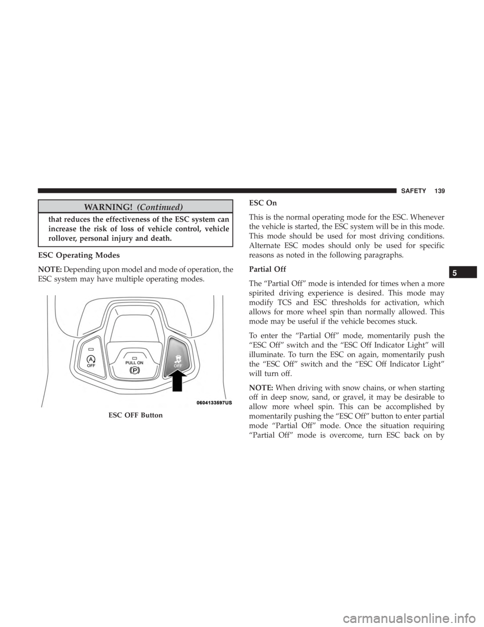
To enter the “Partial Off” mode, momentarily push the
“ESC Off” switch and the “ESC Off Indicator Light” will
illuminate. To turn the ESC on again, momentarily push
the “ESC Off” switch and the “ESC Off Indicator Light”
will turn off.
NOTE:
When driving with snow chains, or when starting
off in deep snow, sand, or gravel, it may be desirable to
allow more wheel spin. This can be accomplished by
momentarily pushing the “ESC Off” button to enter partial
mode “Partial Off” mode. Once the situation requiring
“Partial Off” mode is overcome, turn ESC back on by
Page 143 of 518
WARNING!(Continued)
maneuver, the ESC system will not engage to assist in
maintaining stability. “ESC Off” mode is intended for
off-highway or off-road use only.
ESC Activation/Malfunction Indicator Light And
ESC OFF Indicator Light
The “ESC Activation/Malfunction Indicator
Light” in the instrument cluster will come on
when the ignition is turned to the ON mode. It
should go out with the engine running. If the
“ESC Activation/Malfunction Indicator Light” comes on
continuously with the engine running, a malfunction has
been detected in the ESC system. If this light remains on
after several ignition cycles, and the vehicle has been
driven several miles (kilometers) at speeds greater than
30 mph (48 km/h), see an authorized dealer as soon as
possible to have the problem diagnosed and corrected.
The “ESC Activation/Malfunction Indicator Light” (lo-
cated in the instrument cluster) starts to flash as soon as the
tires lose traction and the ESC system becomes active. The
“ESC Activation/Malfunction Indicator Light” also flashes
when TCS is active. If the “ESC Activation/Malfunction Indicator Light” begins to flash during acceleration, ease
up on the accelerator and apply as little throttle as possible.
Be sure to adapt your speed and driving to the prevailing
road conditions.
NOTE:
•
The “ESC Activation/Malfunction Indicator Light” and
the “ESC OFF Indicator Light” come on momentarily
each time the ignition is turned ON.
• Each time the ignition is turned ON, the ESC system will
be on even if it was turned off previously.
• The ESC system will make buzzing or clicking sounds
when it is active. This is normal; the sounds will stop
when ESC becomes inactive following the maneuver
that caused the ESC activation.
The “ESC OFF Indicator Light” indicates the
customer has elected to have the Electronic Sta-
bility Control (ESC) in a reduced mode.
5
SAFETY 141
Page 157 of 518
system will hold the vehicle at standstill for two seconds
and then release the brakes.
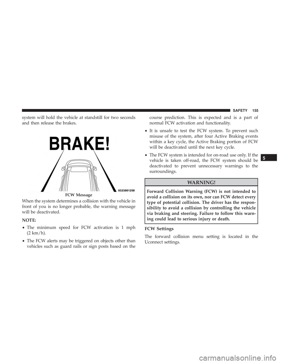
When the system determines a collision with the vehicle in
front of you is no longer probable, the warning message
will be deactivated.
NOTE:
•The minimum speed for FCW activation is 1 mph
(2 km/h).
• The FCW alerts may be triggered on objects other than
vehicles such as guard rails or sign posts based on the course prediction. This is expected and is a part of
normal FCW activation and functionality.
• It is unsafe to test the FCW system. To prevent such
misuse of the system, after four Active Braking events
within a key cycle, the Active Braking portion of FCW
will be deactivated until the next key cycle.
• The FCW system is intended for on-road use only. If the
vehicle is taken off-road, the FCW system should be
deactivated to prevent unnecessary warnings to the
surroundings.
Page 171 of 518
WARNING!(Continued)
driver, should always wear their seat belts whether
or not an air bag is also provided at their seating
position to minimize the risk of severe injury or
death in the event of a crash.
• Wearing your seat belt incorrectly could make your
injuries in a collision much worse. You might suffer
internal injuries, or you could even slide out of the
seat belt. Follow these instructions to wear your seat
belt safely and to keep your passengers safe, too.
• Two people should never be belted into a single seat
belt. People belted together can crash into one an-
other in a collision, hurting one another badly. Never
use a lap/shoulder belt or a lap belt for more than one
person, no matter what their size.
Page 172 of 518
WARNING!(Continued)
•A shoulder belt placed behind you will not protect
you from injury during a collision. You are more
likely to hit your head in a collision if you do not
wear your shoulder belt. The lap and shoulder belt
are meant to be used together.
• A frayed or torn seat belt could rip apart in a collision
and leave you with no protection. Inspect the seat
belt system periodically, checking for cuts, frays, or
loose parts. Damaged parts must be replaced imme-
diately. Do not disassemble or modify the seat belt
system. Seat belt assemblies must be replaced after a
collision.
Lap/Shoulder Belt Operating Instructions
1. Enter the vehicle and close the door. Sit back and adjust
the seat.
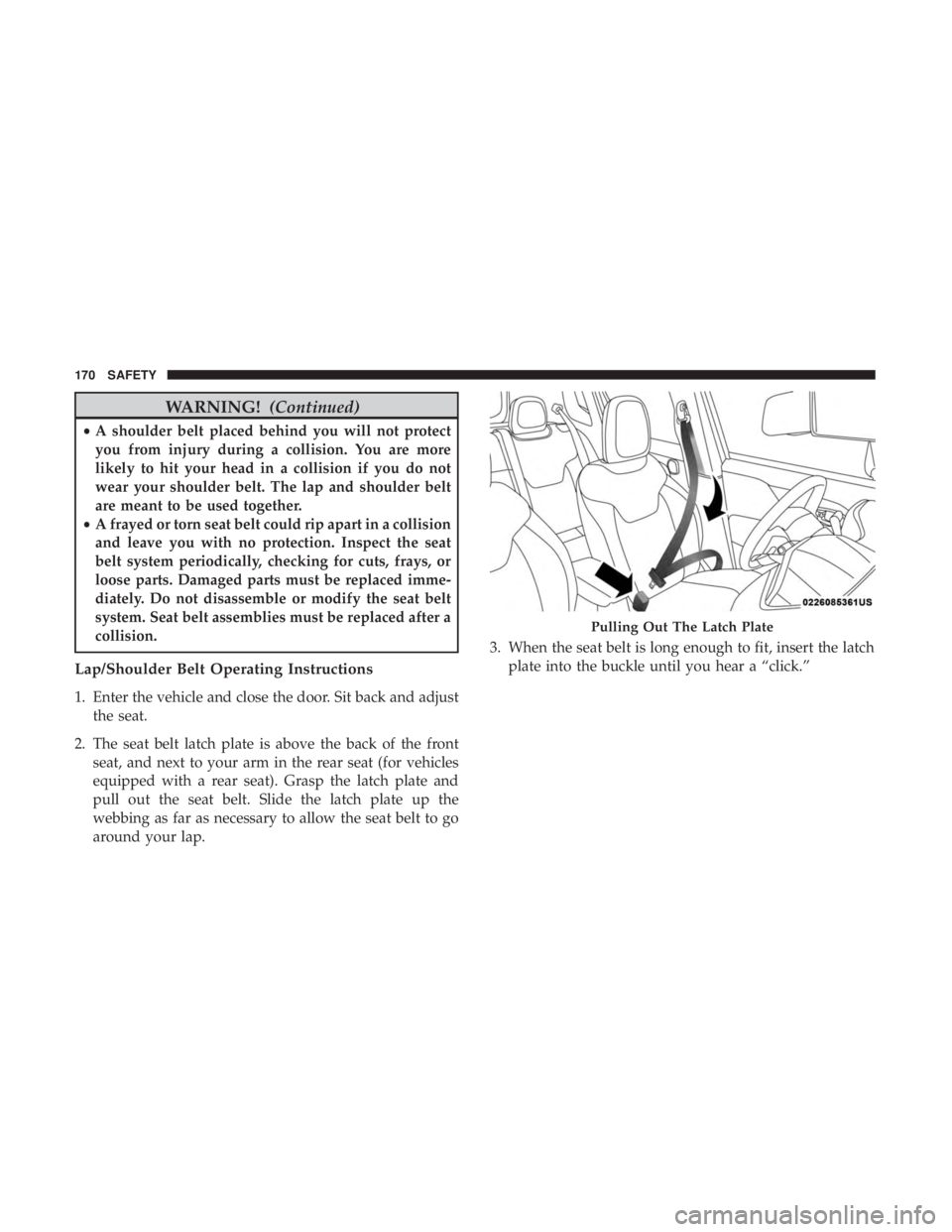
2. The seat belt latch plate is above the back of the front seat, and next to your arm in the rear seat (for vehicles
equipped with a rear seat). Grasp the latch plate and
pull out the seat belt. Slide the latch plate up the
webbing as far as necessary to allow the seat belt to go
around your lap. 3. When the seat belt is long enough to fit, insert the latch
plate into the buckle until you hear a “click.”
Page 178 of 518
WARNING!(Continued)
occupant, the seat belt will not be able to provide
proper restraint and will increase the risk of injury in
a collision.
• When reattaching the mini-latch plate and mini-
buckle, ensure the seat belt webbing is not twisted.
If the webbing is twisted, follow the preceding
procedure to detach the mini-latch plate and mini-
buckle, untwist the webbing, and reattach the mini-
latch plate and mini-buckle.
Seat Belt Extender
If a seat belt is not long enough to fit properly, even when
the webbing is fully extended and the adjustable upper
shoulder belt anchorage (if equipped) is in its lowest
position, your authorized dealer can provide you with a
Seat Belt Extender. The Seat Belt Extender should be used
only if the existing seat belt is not long enough. When the
Seat Belt Extender is not required for a different occupant,
it must be removed.
Page 184 of 518
WARNING!
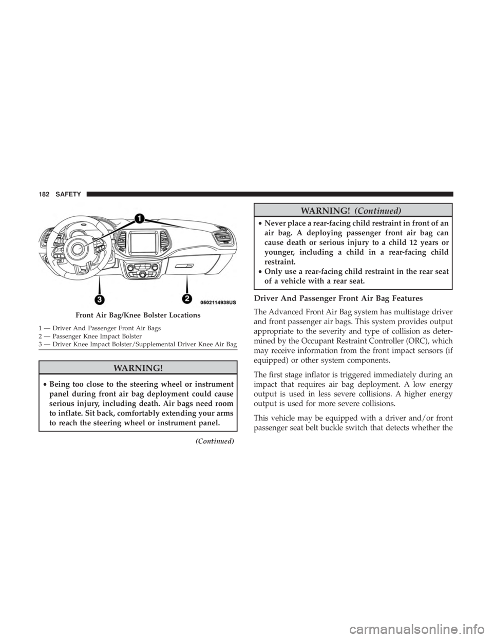
•Being too close to the steering wheel or instrument
panel during front air bag deployment could cause
serious injury, including death. Air bags need room
to inflate. Sit back, comfortably extending your arms
to reach the steering wheel or instrument panel.
(Continued)
Page 191 of 518
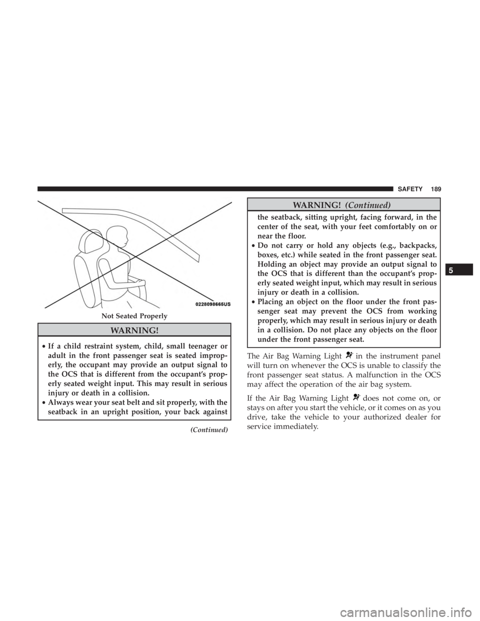
WARNING!
•If a child restraint system, child, small teenager or
adult in the front passenger seat is seated improp-
erly, the occupant may provide an output signal to
the OCS that is different from the occupant’s prop-
erly seated weight input. This may result in serious
injury or death in a collision.
• Always wear your seat belt and sit properly, with the
seatback in an upright position, your back against
(Continued)
Page 193 of 518
WARNING!
•Do not drill, cut, or tamper with the knee impact
bolsters in any way.
• Do not mount any accessories to the knee impact
bolsters such as alarm lights, stereos, citizen band
radios, etc.
Supplemental Driver Knee Air Bag
This vehicle is equipped with a Supplemental Driver Knee
Air Bag mounted in the instrument panel below the
steering column. The Supplemental Driver Knee Air Bag
provides enhanced protection during a frontal impact by
working together with the seat belts, pretensioners, and
front air bags.
Supplemental Side Air Bags
Supplemental Seat-Mounted Side Air Bags (SABs)
This vehicle is equipped with Supplemental Seat-Mounted
Side Air Bags (SABs).
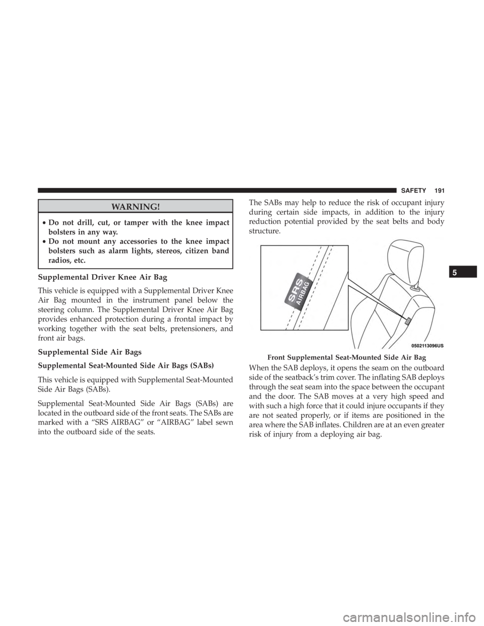
Supplemental Seat-Mounted Side Air Bags (SABs) are
located in the outboard side of the front seats. The SABs are
marked with a “SRS AIRBAG” or “AIRBAG” label sewn
into the outboard side of the seats. The SABs may help to reduce the risk of occupant injury
during certain side impacts, in addition to the injury
reduction potential provided by the seat belts and body
structure.
When the SAB deploys, it opens the seam on the outboard
side of the seatback’s trim cover. The inflating SAB deploys
through the seat seam into the space between the occupant
and the door. The SAB moves at a very high speed and
with such a high force that it could injure occupants if they
are not seated properly, or if items are positioned in the
area where the SAB inflates. Children are at an even greater
risk of injury from a deploying air bag.