change time JEEP DJ 1953 User Guide
[x] Cancel search | Manufacturer: JEEP, Model Year: 1953, Model line: DJ, Model: JEEP DJ 1953Pages: 376, PDF Size: 19.96 MB
Page 90 of 376
DAUNTLESS
V-6
ENGINE
Note:
The rib on
edge
of cap and the conical
boss
on web of connecting rod must be toward
rear
of
engine
in all connecting rod assemblies of left
cyl
inder
bank and toward front of
engine
in all connecting rod assemblies of right cylinder bank.
Dl-50.
Oil
Pump Intake
and
Screen Cleaning
a.
Pry screen from housing and examine for clog
ging due to deposit of sludge or other foreign
material.
b.
Clean
the screen and housing thoroughly in sol
vent; dry with compressed air.
c.
Install
screen in housing.
Dl-51.
Oil Pan Cleaning and Inspection
Inspect
the oil pan for corrosion, dents, leaks, and
other damage. Inspect its mounting flange carefully
for damage or distortion to be certain that it
will
give
a
good
seal.
Dl-52.
Flywheel Cleaning
and
Inspection
Clean
the flywheel with suitable cleaning solvent;
dry
with compressed air. Inspect clutch face for
burned
or scuffed condition and for rivet grooves.
Inspection
for run out or improper mounting is de
scribed
in installation procedure.
Inspect
teeth
of the flywheel
ring
gear for
burrs,
nicks,
and minor distortion. If necessary and pos
sible, use a small emery wheel to remove
burrs
and
reshape teeth. If gear
teeth
are broken,
cracked,
seriously
burred
or deformed, the
ring
gear must be replaced.
Dl-53.
Ring Gear Replacement
a.
Drill
a
hole
between
two
ring
gear teeth; then
split
the gear with a cold chisel. Be careful not to
damage
ring
gear shoulder or seat surfaces of fly
wheel.
b.
Polish several
spots
on the new
ring
gear to be
installed.
With
a hot plate or slowly moving torch,
heat the new
ring
gear until polished
spots
become
blue, about
600°F.
[312°C.].
Caution:
Do not heat the
ring
gear to a temperature
greater than
800°F.
[424°C.].
Excessive heat
will
destroy heat treatment given to
ring
gear during
manufacture.
c.
Quickly
install
ring
gear on flywheel. Chamfered
edge
of
ring
gear must be toward
ring
gear shoulder
of flywheel. Be certain that
ring
gear is seated prop
erly.
Allow
ring
gear to cool slowly, so that it
will
be held tightly in place.
Dl-54.
Flywheel Housing Cleaning and Inspection
Both
flywheel and clutch are enclosed by a fly
wheel housing. Its front surface is bolted to the
engine
cylinder block, and its
rear
surface acts as
front
support to the transmission.
Clean
the fly wheel housing with a suitable cleaning solvent; dry
with
compressed air. Inspect front and
rear
surfaces
for distortion and improper alignment with each
other;
these
planes must be
parallel
to assure
proper
alignment
between
engine
and transmission.
Dl-55.
Camshaft Cleaning
and
Inspection
Clean
both camshaft and camshaft bearing surfaces
with
a suitable cleaning solvent; dry with com
pressed air.
Note:
The steel-backed babbitt-lined camshaft
bearings are pressed into the crankcase.
From
front
to
rear,
each bearing is .030" [0,76 mm.] smaller
in
diameter than the preceding bearing.
From
front
to
rear,
each camshaft
journal
is correspondingly
smaller
in diameter.
The
camshaft bearings must be line reamed to
proper
diameter after being pressed into crankcase.
Since
this operation requires special reaming equip
ment, the original bearings should be retained un
less
they are severly damaged. Slightly scored cam
shaft bearings are satisfactory if the surfaces of camshaft journals are polished, bearings are
polished to remove
burrs,
and
radial
clearance
between
camshaft and bearings is within .0015"
to .004" [0,038 a 0,102 mm.].
Dl-56.
Valve Lifter
and
Push
Rod
Cleaning and Inspection
a.
Examine the cam contact surface at lower end of each valve lifter body. If surface is excessively
worn,
galled, or otherwise damaged, discard the
valve lifter. Also examine the mating camshaft
lobe
for excessive wear or damage.
b.
Disassemble one or two valve lifters, as de
scribed
below, and inspect them for
dirt
or
varnish.
If
they are dirty or have a varnish deposit, clean
and
inspect all twelve valve lifters. Otherwise,
service
only
those
valve lifters which do not operate
properly.
c.
To disassemble each valve lifter, depress the
push
rod seat with a push rod, and remove the
plunger retainer from the valve lifter body with
a
retainer remover. Remove push rod seat and
plunger from valve lifter body. If plunger sticks
in
valve lifter body, place body in large end of
a
plunger remover tool, with plunger downward.
While
holding lifter with thumb, rap the open end
of remover against a block of wood with just enough force to jar the plunger from body. Refer to
Figs.
Dl-20, Dl-22 and Dl-23.
d.
Drain
oil from valve lifter and remove the check
valve retainer,
ball,
valve spring, and plunger
spring.
e. Keep all parts of each valve lifter separated
during
part cleaning and inspection. The valve
lifter
body and plunger are selectively fitted to each other and must not be interchanged with parts
of other valve lifters.
f. Rinse all valve lifter parts in kerosene to remove as much oil as possible.
This
will
reduce contamina
tion of the cleaning solvent. Immerse all parts in cleaning solvent for approximately one hour. The
time required
will
depend on varnish
deposits
and
effectiveness
of the solvent. After the varnish has
dissolved or has
softened
sufficiently to permit re
moval
by wiping, allow parts to
drain.
Varnish
can
then be cleaned from the valve lifter body
with
a
brush.
Rinse the parts in kerosene to dissolve 90
Page 92 of 376
Di
DAUNTLESS
V-6
ENGINE
12721
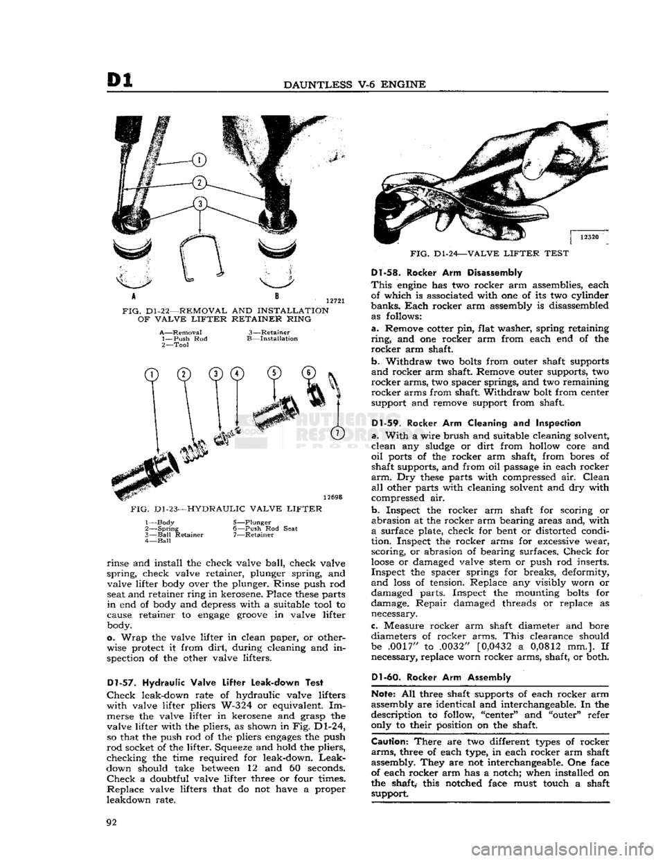
FIG.
D1-22—REMOVAL
AND
INSTALLATION
OF
VALVE
LIFTER
RETAINER
RING
A—Removal'
1—
Push
Rod
2—
Tool
3-
B-
-Retainer
-Installation
T)
0
© ©
6
FIG.
D1-23—HYDRAULIC
VALVE
LIFTER
1—
Body
2—
Spring
3—
Ball
Retainer
4—
Ball
5— -Plunger
6—
Push
Rod
Seat
7—
-Retainer
rinse
and
install
the
check valve
ball,
check valve
spring,
check valve retainer, plunger spring,
and
valve lifter body over
the
plunger. Rinse push
rod
seat and retainer ring in kerosene. Place
these
parts
in
end of
body and depress with
a
suitable tool
to
cause retainer
to
engage
groove
in
valve lifter body.
o.
Wrap
the
valve lifter
in
clean paper,
or
other
wise protect
it
from
dirt,
during cleaning
and in
spection
of the
other valve lifters.
Dl-57.
Hydraulic Valve
Lifter
Leak-down
Test
Check
leak-down rate
of
hydraulic valve lifters
with
valve lifter pliers W-324
or
equivalent.
Im
merse
the
valve lifter
in
kerosene
and
grasp
the
valve lifter with
the
pliers,
as
shown
in
Fig. Dl-24, so that
the
push rod
of the
pliers
engages
the
push
rod
socket
of
the lifter. Squeeze and hold
the
pliers,
checking
the
time required
for
leak-down.
Leak-
down should take
between
12 and 60
seconds.
Check
a
doubtful valve lifter three
or
four times.
Replace
valve lifters that
do not
have
a
proper
leakdown rate.
FIG.
Dl-24—VALVE
LIFTER
TEST
Dl-58.
Rocker
Arm
Disassembly
This
engine
has two
rocker arm assemblies, each of which
is
associated with
one of its two
cylinder
banks.
Each
rocker arm assembly
is
disassembled as follows:
a.
Remove cotter pin, flat washer, spring retaining
ring,
and one
rocker
arm
from each
end of the
rocker
arm shaft.
b.
Withdraw
two
bolts
from outer shaft supports
and
rocker arm shaft. Remove outer supports,
two
rocker
arms, two spacer springs, and
two
remaining
rocker
arms from shaft. Withdraw bolt from center
support
and
remove support from shaft.
Dl-59.
Rocker
Arm Cleaning and
Inspection
a.
With
a
wire brush and suitable cleaning solvent,
clean
any
sludge
or
dirt
from hollow core
and
oil
ports
of the
rocker
arm
shaft, from bores
of
shaft supports, and from
oil
passage
in
each rocker
arm.
Dry
these
parts with compressed
air.
Clean
all
other parts with cleaning solvent and dry with
compressed
air.
b.
Inspect
the
rocker
arm
shaft
for
scoring
or
abrasion
at the
rocker arm bearing areas and, with
a
surface plate, check
for
bent
or
distorted condi
tion. Inspect
the
rocker arms
for
excessive wear,
scoring,
or
abrasion
of
bearing surfaces.
Check
for
loose
or
damaged valve stem
or
push
rod
inserts.
Inspect
the
spacer springs
for
breaks, deformity,
and
loss
of
tension. Replace
any
visibly worn
or
damaged parts. Inspect
the
mounting
bolts
for
damage.
Repair
damaged threads
or
replace
as
necessary.
c.
Measure rocker
arm
shaft diameter
and
bore
diameters
of
rocker arms.
This
clearance should be .0017"
to
.0032"
[0,0432
a
0,0812
mm.]. If
necessary, replace worn rocker arms, shaft,
or
both.
Dl-60.
Rocker
Arm Assembly
Note:
All three shaft supports
of
each rocker arm
assembly are identical and interchangeable. In
the
description
to
follow, "center"
and
"outer" refer only
to
their position
on the
shaft.
Caution:
There
are two
different
types
of
rocker
arms,
three
of
each type,
in
each rocker arm shaft
assembly. They
are not
interchangeable. One face
of each rocker arm
has a
notch; when installed
on
the shaft, this notched face must touch
a
shaft support.
92
Page 96 of 376
Dl
DAUNTLESS
V-6
ENGINE
Note:
During
engine
reassembly, use Perfect Seal
Aerosol
Spray Sealer
Part
No.
994757
on all en
gine
gaskets to ensure against vacuum, oil, gasoline
and
water leaks. Apply to head gaskets, valve covers, water pumps, oil pan gaskets, radiator and
heater
hose
connections, felt gaskets, gasoline and
oil
line connections, stud bolts, spark plug threads,
and
grease retainer washers. Refer to manufac
turer's
instructions on container for proper appli
cation procedure.
Dl-72.
Cylinder
Block
and Crankshaft
Rear
Oil Seals
Braided
fabric seals are pressed into
grooves
of
cylinder
block and
rear
main bearing cap, to
rear
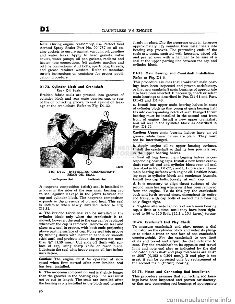
of the oil collecting groove, to seal against oil leak age at the crankshaft. Refer to Fig. Dl-32.
FIG.
Dl-32—INSTALLING
CRANKSHAFT REAR
OIL
SEAL
1—Neoprene
Seal
2—Fabric
Seal
A
neoprene composition (stick) seal is installed in
grooves
in the sides of the
rear
main bearing cap
to seal against leakage in the joints
between
the
cap and cylinder block. The neoprene composition
expands in the presence of oil and heat.
This
seal
is undersize when newly installed. Refer to Fig.
Dl-32.
a.
The braided fabric seal can be installed in the
cylinder
block only when the crankshaft is re moved; however, the seal in the cap can be replaced
whenever the cap is removed. Remove oil seal and place new seal in groove, with both ends projecting
above parting surface of cap. Force seal into
groove
by rubbing down with hammer handle or smooth
stick
until seal projects above the
groove
not more
than
[1,59 mm.]. Cut ends off flush with
sur
face of cap, using sharp knife or razor blade.
Lubricate
the seal with heavy
engine
oil just before
installation.
Caution:
The
engine
must be operated at slow
speed when first started after new braided seal
has been installed.
b. The neoprene composition seal is slightly longer
than
the
grooves
in the bearing cap. The seal must
not be cut to length. The seals are installed after the bearing cap is installed in the block and torqued
firmly
in place. Dip the neoprene seals in kerosene
approximately IV2 minutes, then install seals into
bearing cap grooves. The protruding ends of the seals are, again, squirted with kerosene, wiped off,
and
peaned over with a hammer to be sure of a
seal
at the upper parting line
between
the cap and
cylinder
block.
Dl-73.
Main
Bearing and Crankshaft
Installation
Refer
to Fig. Dl-6.
This
procedure assumes that crankshaft main bear
ings have been inspected and proven satisfactory,
or
that new crankshaft main bearings of appropriate size have been selected. If necessary, check or select
main
bearings as described in Par. Dl-41 and
Pars.
Dl-42 and Dl-43.
a.
Install
four upper main bearing halves in
seats
of cylinder block so that prong of each bearing half
fits into corresponding notch of seat. Flanged thrust
bearing must be installed in the second seat from
front of engine.
Install
a new upper crankshaft
rear
oil seal in the cylinder block as described in
Par.
Dl-72.
Caution:
Upper main bearing halves have an oil groove, while lower halves are plain. They must
not be interchanged.
b. Apply
engine
oil to upper bearing surfaces.
Install
the crankshaft so that its four journals rest
in
the upper bearing halves.
c. Seat all four lower main bearing halves in cor
responding bearing caps.
Install
a new lower
crank
shaft
rear
oil seal and cylinder block
rear
oil seal
described in
Par.
Dl-72, a and b.
Lubricate
all lower
main
bearing surfaces with
engine
oil. Position bear ing caps to cylinder block and crankcase journals.
Install
two cap bolts,
loosely,
at each cap.
d.
It is necessary to align thrust surfaces of the
second main bearing whenever it has been removed
from
the engine. To do this, pry the crankshaft
back
and forth several times, throughout its entire end travel, with cap
bolts
of second main bearing
only finger tight.
e. Tighten alternate cap
bolts
of each main bearing
cap,
a little at a time, until they have been tight ened to 80 to 110 lb-ft. [11,1 a 15,2 kg-m.] torque.
D1-74. Crankshaft End Play Check
To
measure crankshaft end play, mount a dial
indicator
on the cylinder block and index its plung
er
to either a front or
rear
face of one crankshaft
counterweight. Pry the crankshaft to one limit
of its end travel and adjust the dial indicator to
zero. Pry the crankshaft to its
opposite
end travel
limit
and
note
end play as indicated by the dial
indicator.
Crankshaft end play tolerances are .004"
to .008" [0,102 a
0,204
mm.]. If end play is too great, it can be corrected only by replacement of
the second main (thrust) bearing.
Dl-75.
Piston and Connecting Rod
Installation
This
procedure assumes that connecting rod bear ings have been inspected and proven satisfactory,
or
that new connecting rod bearings of appropriate 96
Page 112 of 376
E
FUEL
SYSTEM
9
©
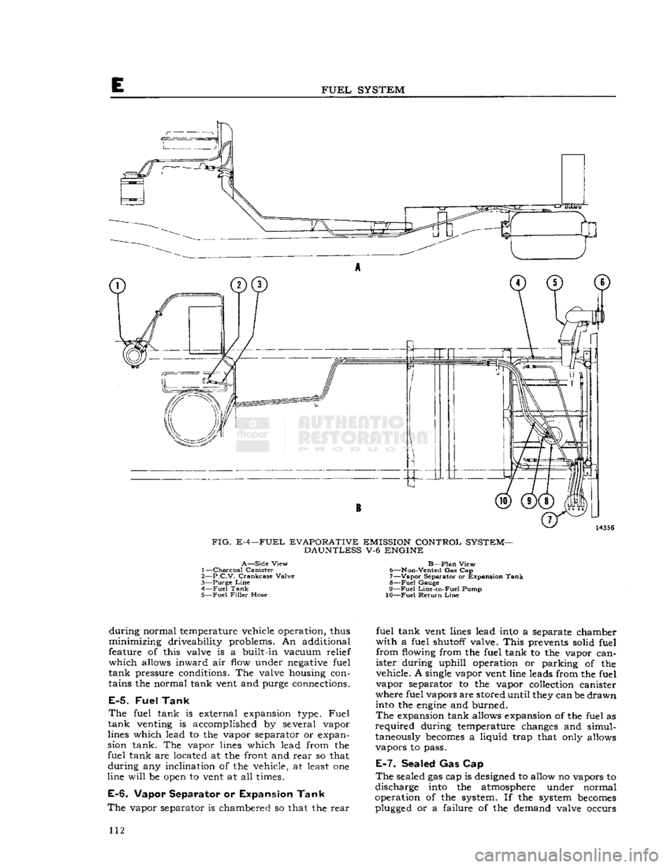
FIG.
E-4—FUEL
EVAPORATIVE
EMISSION
CONTROL
SYSTEM-
DAUNTLESS
V-6
ENGINE
A—Side
View
1—
Charcoal
Canister
2—
P.C.V.
Crankcase
Valve
3—
Purge
Line
4—
Fuel
Tank
5—
Fuel
Filler
Hose
B—Plan
View
6—
Non-Vented
Gas Cap 7—
Vapor
Separator or Expansion
Tank
g—Fuei
Gauge
9—Fuel
Line-to-Fuel
Pump
10—Fuei
Return
Line
during
normal temperature vehicle operation, thus
minimizing
driveability problems. An additional
feature of this valve is a built-in vacuum relief
which
allows inward air flow under negative fuel
tank
pressure conditions. The valve housing con
tains the normal tank vent and purge connections.
E-5.
Fuel Tank
The
fuel tank is external expansion type.
Fuel
tank
venting is accomplished by several vapor
lines which lead to the vapor separator or expan
sion tank. The vapor lines which lead from the
fuel tank are located at the front and
rear
so that
during
any inclination of the vehicle, at least one
line
will
be open to vent at all times.
E-6.
Vapor Separator
or
Expansion Tank
The
vapor separator is chambered so that the
rear
fuel tank vent lines lead into a separate chamber
with
a fuel shutofl valve.
This
prevents solid fuel
from
flowing from the fuel tank to the vapor can
ister during uphill operation or parking of the
vehicle. A single vapor vent line leads from the fuel
vapor separator to the vapor collection canister
where fuel vapors are stored until they can be drawn into the
engine
and burned.
The
expansion tank allows expansion of the fuel as
required
during temperature changes and simul taneously
becomes
a liquid trap that only allows
vapors to pass.
E-7.
Sealed
Gas Cap
The
sealed gas cap is designed to allow no vapors to
discharge into the atmosphere under normal
operation of the system. If the system
becomes
plugged or a failure of the demand valve occurs 112
Page 156 of 376
F2
EXHAUST EMISSION CONTROL SYSTEMS
the throttle
stop
screw to idle the
engine
at 650
to 700 rpm.
F2-17. Carburetor Idle Setting
The
"Lean
Best
Idle"
Method of Idle Setting is as
follows:
a.
Any scheduled service of ignition system should
precede this adjustment
b.
Connect tachometer to engine.
c.
Warm
up
engine
and stabilize temperatures.
d.
Adjust
engine
idle to speed desired, using throt
tle idle speed adjusting screw.
e.
Turn
idle mixture screws out (counterclockwise)
until
a
loss
of
engine
speed is indicated; then slowly
turn
mixture screws in (clockwise-leaner)
until
maximum speed (rpm) is reached. Continue
turning
in (clockwise) until speed begins to drop;
turn
mixture adjustment back out (counterclock
wise-richer)
until maximum speed is just regained
at
a "lean as possible" mixture adjustment.
F2-18. Distributor
The
ignition distributor used with the
Exhaust
Emission
Control
System is the same as that used
on
engines
without
Exhaust
Emission
Control.
Check
the distributor cam dwell angle and point
condition.
Check
ignition timing and adjust to specifications shown on the last
page
of this section.
F2-19.
Anti-Backfire
Valve
The
anti-backfire valve remains closed except when
the throttle is closed rapidly from an open position.
To
check the valve for proper operation, accelerate
the
engine
in neutral, allowing the throttle to close
rapidly.
The valve is operating satisfactorily when
no exhaust system backfire occurs. A further check
to determine whether the valve is functioning can
be made by removing from the anti-backfire valve
the large
hose
which connects the valve to the
pump.
With
a finger placed over the open end of
the
hose
(not the valve), accelerate the
engine
and allow the throttle to close rapidly. The valve is
operating satisfactorily if a momentary air rushing
noise is audible.
F2-20.
Check
Valve
The
check valves in the lines to the air distribution manifolds prevent the reverse flow of exhaust
gases
to the pump in the event the pump should, for
any
reason,
become
inoperative or should exhaust
pressure
ever exceed pump pressure.
To
check this valve for proper operation, remove the air supply
hose
from the pump at the check
valve.
With
the
engine
running, listen for exhaust
leakage at the check valve which is connected to
the distribution manifold.
F2-21.
Air
Pump
Check
for proper drive belt tension with belt tension
gauge
W-283. The belt strand tension should be 60 pounds measured on the
longest
accessible span
between two pulleys. DO NOT PRY ON THE
DIE
CAST
PUMP
HOUSING. To
check the pump for proper operation, remove
the air
outlet
hose
at the pump.
With
the
engine
running,
air discharge should be felt at one of
the pump
outlet
openings. The pump
outlet
air
pressure,
as determined by the relief valve, is preset
and
is not adjustable.
The
air pump
rear
cover assembly, housing the pressed in inlet and discharge tubes, and the pres
sure
relief valve are the only pump components
recommended for service replacement. These parts
are
to be replaced only when damaged as a result
of handling or in the event the relief valve was
tampered with.
F2-22.
Intake Manifold
Intake
manifold leaks must not be overlooked. Air
leakage at the intake manifold may be compen
sated for by
richer
idle mixture setting, however, this
will
usually cause uneven fuel-air distribution
and
will
always result in
loss
of performance and
exhaust emission control. To check for air leakage
into the intake manifold, apply kerosene or naph
tha,
on the intake manifold to cylinder head joints
and
observe whether any changes in
engine
rpm
occur.
If an air leak is indicated, check the mani
fold to cylinder head bolt torque. The correct torque is 25-35 lbs. ft. [3,46 a 4,84 kg-m.]. If the
leak
is
still
evident,
loosen
the manifold assembly
and
torque-tighten the bolts evenly.
Start
from the center and use proper torque values. Replace the
manifold
gasket if the leak
still
exists.
Clean
both
mating surfaces and check for
burrs
or other ir
regularities.
Always
torque the bolts evenly to the specified
torque value to prevent warpage.
F2-23.
Carburetor
Air
Cleaner
—Oil
Bath
Every
6,000
miles [9,600 km.] disconnect attach
ing
hoses
and unscrew the wing nut from the top
of the air cleaner and lift it off the carburetor.
Lift
the cover and filter element off the oil sump.
Clean
the inside surface of the sump and
refill
to
indicated
oil level with SAE 40 or 50
engine
oil
above 32 F; SAE 20 below 32 F.
Wash
filter element in kerosene and
drain.
Reassemble the air
cleaner
and install on carburetor.
More
frequent cleaning and replacement are advis able when the car is operated in dusty areas or on
unpaved
roads. Accumulated
dirt
restricts air flow,
reducing
fuel economy and performance.
F2-24.
REMOVAL PROCEDURES
The
following paragraphs
give
the procedures for removing the major units of the exhaust emission
control
system and the required equipment needed.
F2-2S.
Air
Pump
Loosen
the air pump mounting bracket bolts. Re move the air pump air hose(s). Separate the air pump from its mounting bracket. At time of install
ation,
torque tighten the air pump mounting bolts
to
30-40
lbs.-ft [4,15 a 5,53 kg-m.].
Adjust
the
belt strand tension to 60 pounds. 156
Page 166 of 376
G
COOLING SYSTEM and
the outlet
hose
is connected to the water pump
housing.
When
installing a new hose, clean the pipe connec
tions and apply a thin layer of nonhardening seal
ing compound. Hose clamps should be properly
located over the connections to provide secure fastening. The pressurized cooling system pressure
can
blow off improperly installed hoses.
G-8.
Cylinder
Block
Any
coolant leaks at the engine block water joints
are
aggravated by pump pressure in the water
jacket
and by pressure developed in the cooling system when the pressure cap is in place.
Small
leaks showing up only as moist
spots
often
cannot
be detected when the engine is hot except by the
appearance of rust, corrosion, and dye stains where
leakage evaporated. Also, expansion and contrac tion of the engine block resulting from extreme
temperature changes can aggravate leaks. For
these
reasons, when checking for coolant leaks inspect
the block when it is cold and while the engine is
running.
A
leaking
drain
cock or plug that cannot be stopped
leaking
by tightening should be replaced.
Leaking
core-hole expansion plugs should be replaced.
If
tightening gasketed joints
will
not correct leak
age, install new gaskets. Use a sealing compound
where recommended.
G-9.
Thermostat
a.
The cooling system of the engine is designed
to provide adequate cooling under most adverse conditions. However, it is necessary to employ
some
device to provide quick warming and to prevent
overcooling during normal operation. Automatic
control
of engine operating temperature is provided
by a water flow control thermostat installed in the
water
outlet of the
Hurricane
F4 engine. The ther
mostat is a heat-operated valve. It should always
be maintained in working order and the vehicle
should never be driven without one installed as there would then be no control of engine tempera
ture.
The temperature at which the thermostat
opens
is preset and cannot be altered.
b.
The thermostat on the
Hurricane
F4 engine is
located in a housing on the top front of the cylinder
head.
On the Dauntless V-6 engine it is located
in
the thermostat housing of the air intake manifold.
The
standard engine thermostat for the
Hurricane
F4
and Dauntless V-6 engine has a normal rating
of
190°F.
[87.8°C]
and should begin to open at
a
coolant temperature between
180°F.
[82°C]
to
192°F.
[89°C]
and be fully open at
202°F.
[94°C.].
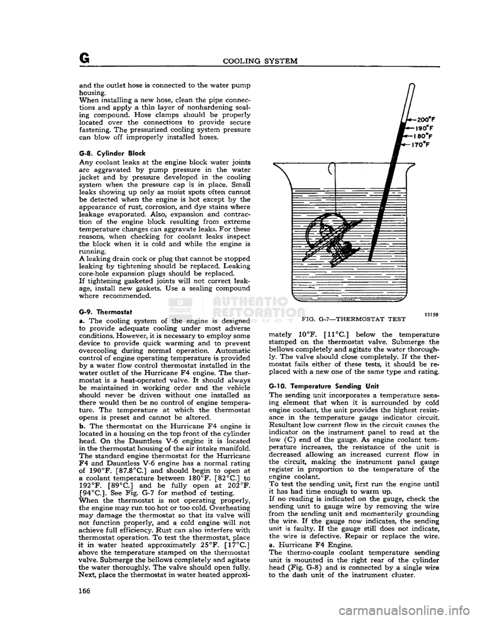
See Fig. G-7 for method of testing.
When
the thermostat is not operating properly, the engine may
run
too hot or too cold. Overheating
may
damage the thermostat so that its valve
will
not function properly, and a cold engine
will
not achieve
full
efficiency.
Rust
can also interfere with
thermostat operation. To
test
the thermostat, place
it
in water heated approximately
25°F.
[17°C]
above the temperature stamped on the thermostat
valve.
Submerge the bellows completely and agitate
the water thoroughly. The valve should open fully.
Next, place the thermostat in water heated approxi-
FIG.
G-7—THERMOSTAT
TEST
mately 10°F.
[11°C]
below the temperature
stamped on the thermostat valve. Submerge the bellows completely and agitate the water thorough
ly.
The valve should close completely. If the ther
mostat fails either of
these
tests, it should be re placed with a new one of the same type and rating.
G-10. Temperature
Sending Unit
The
sending unit incorporates a temperature sens ing element that when it is surrounded by cold engine coolant, the unit provides the highest resist
ance in the temperature
gauge
indicator
circuit.
Resultant
low current flow in the circuit causes the
indicator
on the instrument panel to read at the low (C) end of the
gauge.
As engine coolant tem
perature
increases, the resistance of the unit is
decreased allowing an increased current flow in
the
circuit,
making the instrument panel
gauge
register in proportion to the temperature of the engine coolant.
To
test
the sending unit, first run the engine until
it
has had time enough to warm up.
If
no reading is indicated on the
gauge,
check the
sending unit to
gauge
wire by removing the wire
from
the sending unit and momentarily grounding
the wire. If the
gauge
now indicates, the sending
unit
is faulty. If the
gauge
still
does
not indicate, the wire is defective.
Repair
or replace the wire,
a.
Hurricane
F4 Engine.
The
thermo-couple coolant temperature sending
unit
is mounted in the right
rear
of the cylinder head (Fig. G-8) and is connected by a single wire
to the dash unit of the instrument cluster. 166
Page 187 of 376
'Jeep'
UNIVERSAL
SERIES SERVICE
MANUAL
H
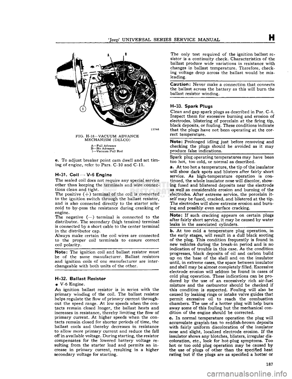
12746
FIG.
H-l8—VACUUM
ADVANCE
MECHANISM
(DELCO)
A—Full
Advance
B—No
Advance
1—Vacuum
Pull
Rod
e.
To adjust breaker point cam dwell and set tim
ing of engine, refer to
Pars.
C-10 and
C-ll.
H-31. Coil
— V-6 Engine
The
sealed coil
does
not require any special service
other than keeping the terminals and wire connec
tions clean and tight.
The
positive (+) terminal of the coil is connected
to the ignition switch through the ballast resistor,
and
is also connected directly to the starter
sole
noid to by-pass the resistance during cranking of
engine.
The
negative (—) terminal is connected to the
distributor.
The secondary (high tension) terminal
is connected by a short cable to the center terminal
in
the distributor cap.
Always
make certain the coil wires are connected to the proper coil terminals to ensure correct
coil
polarity.
Note:
The ignition coil and ballast resistor must
be of the same manufacturer. Ballast resistors
and
ignition coils of one manufacturer are interchangeable with both units of the other. H-32.
Ballast
Resistor
•
V-6 Engine.
An
ignition ballast resistor is in series with the
primary
winding of the coil. The ballast resistor
helps regulate the flow of
primary
current through
out the speed range. At low
speeds
when the con
tacts remain closed longer, the ballast heats and
increases in resistance, thereby limiting the flow of
primary
current. At higher
speeds
when the con
tacts remain closed for shorter periods of time, the ballast
cools
and thereby decreases in resistance
to allow more
primary
current and reduce the
fall
off
in
available voltage.
During
starting, the resistor compensates for the lowered battery
voltage
re
sulting from the starter load and permits an in crease in
primary
current, resulting in a higher
secondary
voltage
for starting.
The
only
test
required of the ignition ballast re
sistor is a continuity check. Characteristics of the ballast produce wide variations in resistance with
changes in ballast temperature. Therefore, check ing
voltage
drop across the ballast would be mis
leading.
Caution:
Never make a connection that connects
the ballast across the battery as this
will
burn
the ballast resistor winding.
H-33.
Spark
Plugs
Clean
and gap
spark
plugs as described in
Par.
C-4.
Inspect them for excessive burning and erosion of
electrodes, blistering of porcelain at the firing tip,
black
deposits, or fouling. These conditions indicate
that the plugs have not been operating at the cor
rect
temperature.
Note:
Prolonged idling just before removing and
checking the plugs should be avoided as it may
produce false indications.
Spark
plug operating temperatures may have been
too hot, too cold, or normal as described.
a.
At too hot a temperature, the tip of the insulator
will
show
dark
spots
and blisters after fairly short service. As high-temperature operation is con
tinued, the whole insulator
nose
will
discolor, show
ing fused and blistered
deposits
near the electrode
as well as considerable erosion and burning of the
electrodes. After extreme service, the porcelain it self may be fused, cracked, and blistered at the tip.
The
electrodes
will
show extreme erosion and
burn
ing and possibly even surface cracking.
Note:
If such cracking appears on certain plugs
after fairly short service, it may be caused by water
leaks in the associated cylinders.
b. At too cold a temperature plug operation, in
the early
stages,
will
result in a
dull
black
sooting
of the plug.
This
condition frequently is found in new vehicles during the break-in period and is no
indication of trouble in this case. As the condition progresses, black
deposits
of oil and carbon build
up on the base of the shell and on the insulator
until,
in extreme cases, the space
between
insulator
and
shell may be almost completely filled. Excessive
electrode erosion
will
seldom be found in cases of cold plug operation. These indications can be pro
duced by the use of an excessively
rich
air-fuel mixture and the carburetor should be checked if
this condition is suspected. Fouling
will
also be
caused by leaking rings or intake valve
guides
that
permit excessive oil to reach the combustion
chambers.
The use of a hotter plug
will
help
burn
away
some
of this fouling but the mechanical con dition of the
engine
should be corrected.
c. In normal temperature operation the plug
will
accumulate grayish-tan to reddish-brown
deposits
with
fairly uniform discoloration of the insulator
nose
and slight, localized electrode erosion. If the
insulator shows any blotches, blisters,
irregular
dis
coloration, etc., look for hot-plug symptoms. Too
hot or too cold plug operation may be caused by
the use of plugs of other than the specified heat
rating
but if the plugs are as specified a hotter or 187
Page 301 of 376
'Jeep'
UNIVERSAL
SERIES SERVICE
MANUAL
N
13189
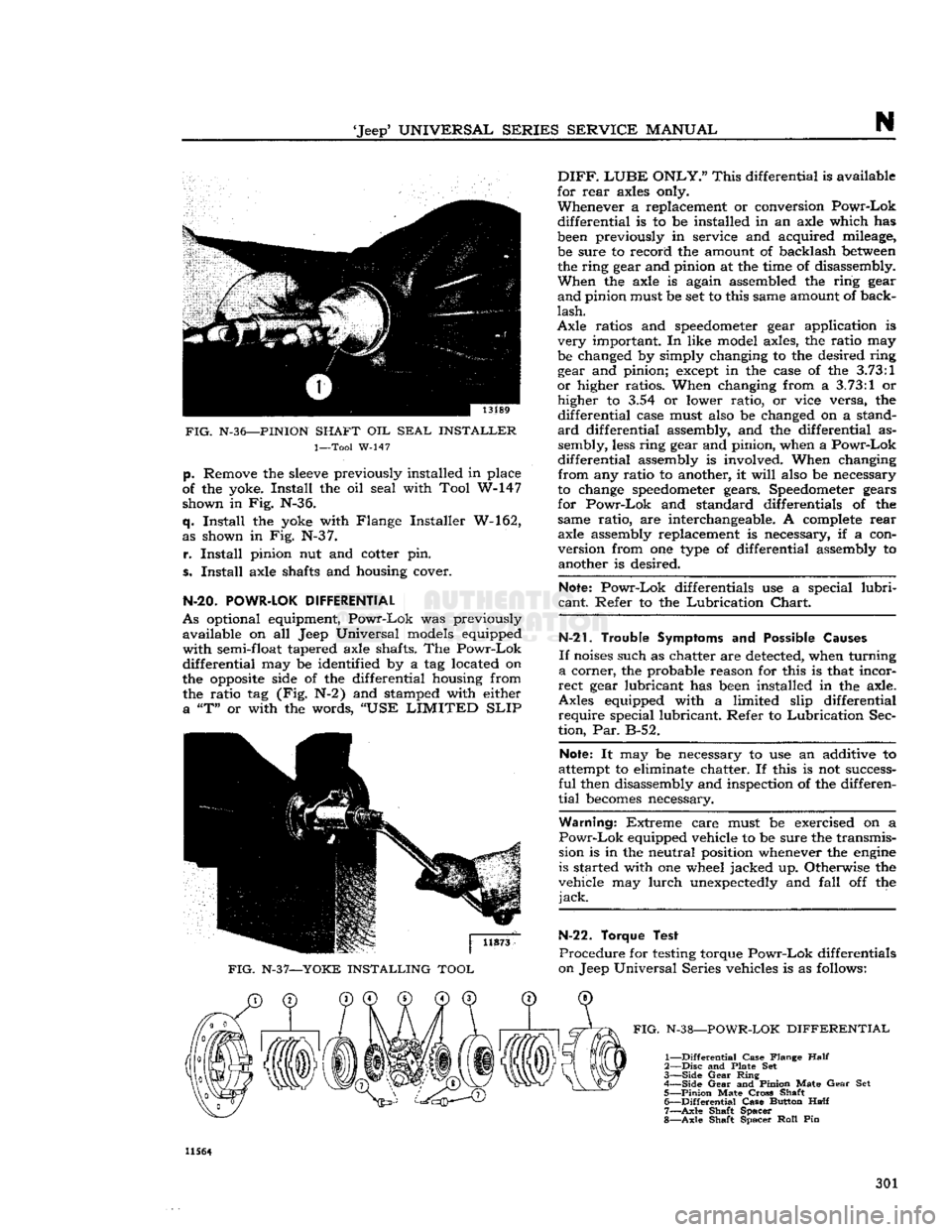
FIG.
N-36—PINION
SHAFT OIL
SEAL
INSTALLER
1—Tool
W-147
p.
Remove
the
sleeve
previously installed in
place
of
the yoke. Install the oil
seal
with
Tool
W-147 shown in Fig. N-36.
q. Install the yoke
with
Flange
Installer W-162,
as shown in Fig. N-3 7.
r.
Install pinion nut and cotter pin.
s. Install axle
shafts
and housing cover.
N-20.
POWR-LOK
DIFFERENTIAL
As
optional equipment, Powr-Lok was previously available on all
Jeep
Universal
models
equipped
with
semi-float
tapered
axle
shafts.
The Powr-Lok
differential
may be identified by a tag located on
the opposite
side
of the differential housing
from
the ratio tag (Fig. N-2) and
stamped
with
either a "T" or
with
the words, "USE
LIMITED
SLIP
FIG.
N-37—YOKE INSTALLING TOOL
DIFF.
LUBE
ONLY."
This differential is available
for
rear
axles
only.
Whenever a
replacement
or conversion Powr-Lok
differential
is to be installed in an axle which has
been
previously in
service
and acquired mileage, be
sure
to record the amount of backlash
between
the ring
gear
and pinion at the time of
disassembly.
When the axle is again
assembled
the ring
gear
and pinion must be set to this
same
amount of
back
lash.
Axle
ratios and
speedometer
gear
application is very important. In
like
model
axles,
the ratio may
be
changed
by simply changing to the desired ring
gear
and pinion;
except
in the
case
of the
3.73:1
or higher ratios. When changing
from
a
3.73:1
or higher to 3.54 or lower ratio, or vice
versa,
the
differential
case
must
also
be
changed
on a
stand
ard differential
assembly,
and the differential as sembly,
less
ring
gear
and pinion, when a Powr-Lok
differential
assembly
is involved. When changing
from
any ratio to
another,
it
will
also
be
necessary
to
change
speedometer
gears.
Speedometer
gears
for
Powr-Lok and
standard
differentials of the
same
ratio, are
interchangeable.
A complete
rear
axle
assembly
replacement
is
necessary,
if a con
version
from
one type of differential
assembly
to
another
is desired.
Note: Powr-Lok differentials use a special
lubri
cant.
Refer to the Lubrication Chart.
N-21.
Trouble Symptoms and
Possible
Causes
If
noises
such
as
chatter
are
detected,
when turning
a corner, the probable
reason
for this is that incor
rect
gear
lubricant has
been
installed in the axle.
Axles
equipped
with
a
limited
slip differential require special lubricant. Refer to Lubrication
Sec
tion,
Par. B-52.
Note: It may be
necessary
to use an additive to
attempt to eliminate
chatter.
If this is not
success
ful
then
disassembly
and inspection of the differen
tial
becomes
necessary.
Warning:
Extreme
care
must be exercised on a
Powr-Lok
equipped vehicle to be
sure
the transmis
sion is in the neutral position
whenever
the
engine
is
started
with
one wheel jacked up. Otherwise the
vehicle may lurch unexpectedly and
fall
off the
jack.
N-22. Torque Test
Procedure
for testing torque Powr-Lok differentials
on
Jeep
Universal
Series
vehicles is as follows:
FIG.
N-38—POWR-LOK DIFFERENTIAL
1—
Differential
Case Flange
Half
2—
Disc
and Plate Set
3—
Side
Gear
Ring
4— Side
Gear
and Pinion Mate
Gear
Set
5—
Pinion
Mate
Cross
Shaft 6—
Differential
Case Button
Half
7—
Axle
Shaft Spacer
8—
Axle
Shaft Spacer
Roll
Pin 11564
301
Page 343 of 376
'Jeep*
UNIVERSAL
SERIES
SERVICE
MANUAL
R
frame.
This
could cause the already aligned sec
tions of the frame to
become
misaligned or weak ened.
R-3.
Frame Dimensions
Points for measuring frame alignment on vehicles
equipped with the F4
engine
are shown in
Fig.
R-l
and
R-2.
The correct measurements for each model
are
given in the table. Point A is at the front of the
frame.
A-B
and C-D are the distances
between
spring
shackle
bolt and spring pivot bolt frame centers
measured
on a line parallel with the frame center-
line.
E and F show the shackle bolt centers in
rela
tion (above or below) to the pivot bolt centers.
On
vehicles equipped with V6
engines
the frame dimensions are shown in Fig. R-3.
CJ-3B
A-B
44.31"
[112,55
cm.]
C-D
. . . . . .48.48"
[123,14
cm.]
Width
Front
29%" [74,3 cm.]
Width
Rear
29M" [74,3 cm.]
"E"
above .3W [8,18 cm.]
"F"
above 4%* [10,56 cm.]
CJ-5,
CJ-5A,
CJ-6,
CJ-6A,
DJ-5, DJ-6
A-B
.47.08"
[119,58
cm.]
C-D.
52.37"
[133,02
cm.]
Width
Front
2934"
[74,3 cm.]
Width
Rear
29j|" [74,3 cm.]
"E"
above 3%" [8,18 cm.]
"F"
above. .5%" [15,0 cm.]
R-4.
Straightening Frame
In
case the bending or twisting of the frame is not
excessive, it may be straightened.
This
should be
done
cold, as excessive heat applied to the frame
will
weaken it. For this reason it is recommended that badly damaged frame parts be replaced.
Note:
A technique known as "controlled heat" can
be utilized where a frame section is "squashed" and must be brought out without "tearing" or excessive
stretch
to the metal.
R-5.
Front
Axle
Alignment
After
it has been determined that the frame is prop
erly
aligned, the front axle alignment with the
frame
can be checked. The front axle is square
with
the frame if the distance
between
the front
and
rear
axle is the same on both sides. The dis
tance from the spring upper bushings to the front
axle on both sides should be equal.
Note:
Always inspect the springs for broken spring
center
bolts
when checking the frame and axle
alignment.
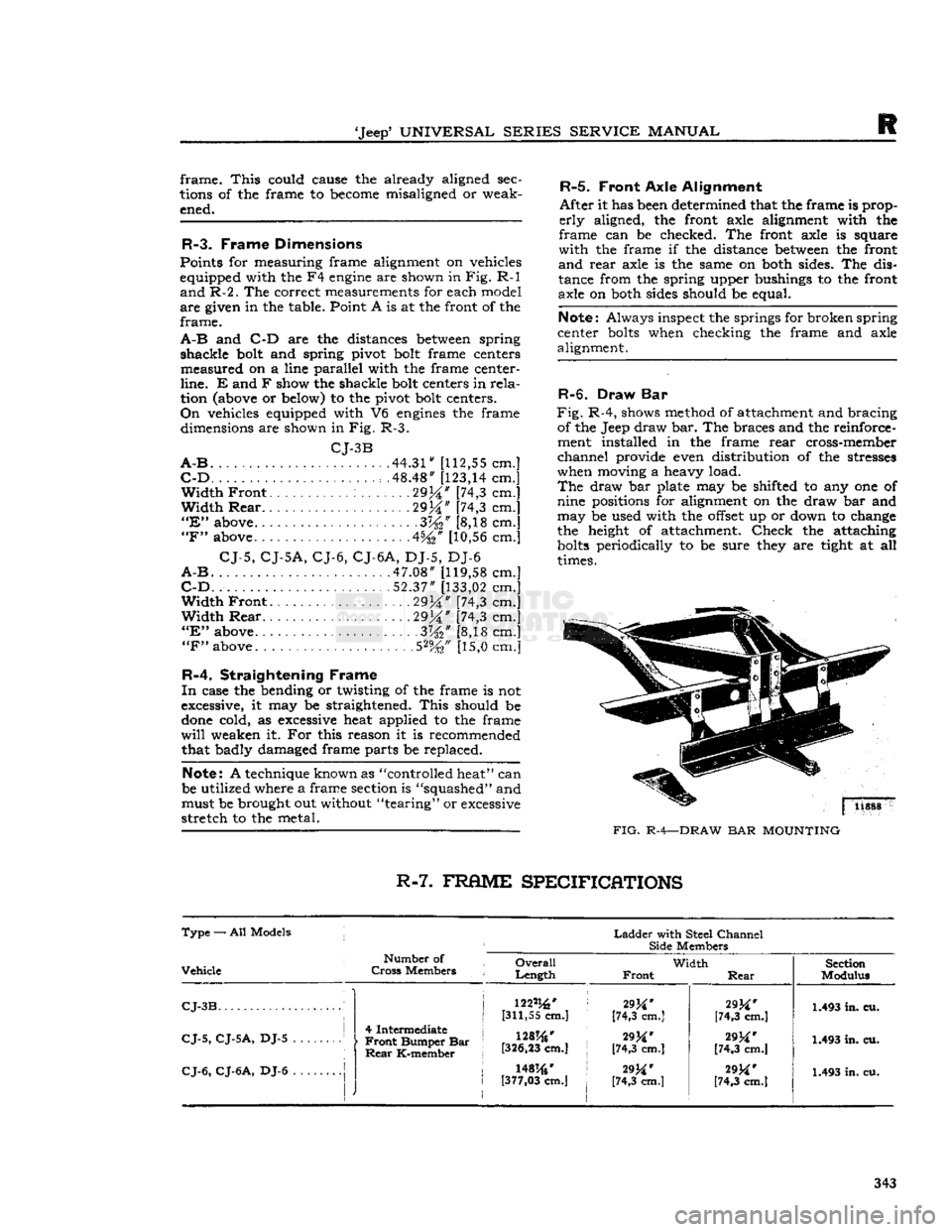
R-6. Draw Bar
Fig.
R-4, shows method of attachment and bracing of the Jeep draw bar. The braces and the reinforce
ment installed in the frame
rear
cross-member
channel
provide even distribution of the stresses
when moving a heavy load.
The
draw bar plate may be shifted to any one of
nine positions for alignment on the draw bar and
may
be used with the
offset
up or down to change
the height of attachment.
Check
the attaching
bolts
periodically to be sure they are tight at all
times.
FIG.
R-4—DRAW
BAR
MOUNTING
R-7.
FRflME
SPECIFICATIONS
Type
— All Models j
Ladder
with Steel
Channel
Side
Members
Vehicle
Number
of
Cross
Members
Overall
Length
Width
Front
Rear
Section
Modulus
CJ-3B
i
CJ-5,
CJ-5A,
DJ-5 1
j
4 Intermediate j
•
Front
Bumper Bar
Rear
K-member 122%'
[311,55 cm.]
128%'
[326,23
cm.] 29^*
[74,3 cm.]
[74,3 cm.]
29M'
[74,3 cm.]
[74,3 cm.] 1.493 in. cu.
1.493 in. cu.
CJ-6,
CJ-6A,
DJ-6
|
J
1
I
r
\mw t
[377,03
cm.]
29M'
[74,3 cm.]
29M'
[74,3 cm.] 1.493 in. cu.
343
Page 357 of 376
'Jeep'
UNIVERSAL SERIES SERVICE
MANUAL
u
MISCEIiLaNEOUS
Contents
SUBJECT
PAR.
Abbreviations
U-15
Extra
Equipment U-2
Front
Bumper Weight U-9
Governor
U-3
Governor
Adjustment U-4
Governor
Maintenance. U-6
U-1. GENERAL
Miscellaneous information included in this sectioi
includes coverage of extra equipment, special
tools,
torque specifications, and charts and tables.
U-2. EXTRA
EQUIPMENT
Much
of the utility of the
*
Jeep*
Universal
is due to
the extra equipment which has been designed to adapt it for farming and industry. The mainte
nance and use of
some
of this equipment is out
lined
in this section.
U-3.
Governor Assembly
The
Novi governor is supplied for models equipped
with
the F4 engine.
This
is a centrifugal type governor and is illustrated in Fig. U-2. Complete
installation
instructions are supplied with each
assembly. Adjustment and operating procedures
are
given below.
U-4.
Governor Adjustment
a.
Adjust the carburetor to obtain smooth
engine
idle at 600 rpm., then
stop
the engine.
b.
Check
throttle linkage to ensure maximum
throttle opening. Be certain that throttle and
governor linkage is free.
c.
Place the carburetor throttle in wide-open posi tion and
pull
the governor control handle out to
the last notch. Adjust the governor to bellcrank
rod
so that the linkage
will
hold the carburetor
throttle in wide-open position.
d.
Close the governor control and start the
engine
Again
pull
the control out to the last notch and
adjust
the length of the cable at adjusting yoke so
that the
engine
will
run at
2600
rpm. Close the
control
to recheck the linkage for free action and
to make sure the
engine
will
return to 600 rpm.
idle speed.
If
the
engine
runs faster than this speed,
loosen
the lock nut which locks the governor hand control
handle on the dash to the rod and back off the
handle until the carburetor idle speed adjusting
screw
bears on the stop. Tighten the lock nut.
In
the absence of electrical tachometer equipment,
engine
speed may be determined by the speedom
eter. Safely
jack
up the
rear
wheels and be sure the front wheel drive is not
engaged.
When driving
the
rear
wheels in high or direct transmission gear,
the
speedometer
will
read from 13j^ to 15 mph. [21.6 to 24.0 kph.] at an
engine
speed of from 900
to 1000 rpm.
SUBJECT
PAR.
Heater
U-10 Miscellaneous Data U-16
Pintle
Hook 1X7
Special
Tools. U-ll
Torque
Specifications U-13, 14, 15
Standard
and Recommended Tools
j.
.U-12
U-5.
Novi Governor Operation /
The
Novi governor is directly belted to the F4
engine
as no clutch is provided to disconnect the
drive.
To
operate the vehicle
WITHOUT
governor con
trol,
push the governor hand control all the way
IN
against the instrument panel.
To
operate the vehicle
WITH
governor control,
pull
the governor hand control handle out. The
hand
control has nine notched positions. Pulling the
control
out to the first notch
sets
the controlled
engine
speed at approximately 1000 rpm. and each successive notch increases the speed 200 rpm.
until
2600
rpm. is reached in the ninth notch. The
hand
control may be released by turning the han dle one-quarter
turn
in either direction.
When
the
engine
is being operated under governor
control
(hand control out) the controlled
engine
speed may be
exceeded
at any time by depressing
the
foot
accelerator in the conventional manner to
secure a greater carburetor throttle opening than
that determined by the governor hand control
setting.
U-6.
Governor Maintenance
The
belt tension may be adjusted by raising or
lowering the governor in the slotted
holes
in the mounting bracket. Keep the pulleys and belt free
of
dirt
and oil. Belt slippage
will
affect governor
operation and a tight belt may cause
rapid
wear
of the governor shaft and bearings. Adjust it to
allow Yi' [12,7 mm.] depression midway
between
the pulleys with thumb pressure.
There
is little wear of the internal parts for they
operate in oil. The governor housings are equipped
with
both
fill
and
drain
plugs and also with level
indicating
plugs.
Check
the oil level at each vehicle
lubrication
and change the oil each time the en
gine
oil is changed using the same grade oil used
in
the engine.
Caution:
Do not
fill
the governor housing above
the level plug. Overfilling
will
prevent governor
control
and possibly cause damage to governor in
ternal
parts. The capacity of
these
governors is two fluid ounces [59,15 cm3]. The filler plug is
also a vent which should be cleaned thoroughly at
each oil change to be sure that the vent operates.
U-7.
Pintle Hook
The
standard type pintle hook, Fig. U-1, affords a
safe, easy hitch for towing a
trailer
or other vehicle. 357