width JEEP DJ 1953 User Guide
[x] Cancel search | Manufacturer: JEEP, Model Year: 1953, Model line: DJ, Model: JEEP DJ 1953Pages: 376, PDF Size: 19.96 MB
Page 272 of 376
K
TRANSFER
CASE
the brake drum and companion
flange
by remov
ing bolts, lockwashers, and nuts.
b.
Remove the oil seal with Tool W-251, as shown
in
Fig. K-7.
c.
Remove
speedometer
driven gear assembly.
d.
Remove the cap screws attaching the cap and
brake
backing plate to the case.
Take
precautions
not to
lose
or damage bearing adjusting shims placed
between
the cap and the transfer case
housing.
e. Separate the
rear
cap and brake backing plate
assembly. See Section P for brake service pro
cedures.
f. Remove
speedometer
driving gear.
K-6.
Transfer
Case
Reassembly
•
Refer to Fig. K-1, K-2.
Reassembly
of the transfer case is reversal of the
foregoing
procedure of disassembly. The output shaft snap ring may
best
be installed with Tool
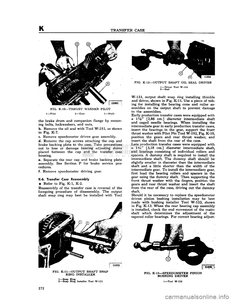
FIG.
K-11—OUTPUT
SHAFT
SNAP
RING
INSTALLER
1—
Snap
Ring
2—
Snap
Ring
Installer Tool W-131
FIG.
K-12—OUTPUT
SHAFT
OIL
SEAL
DRIVER
1—
Driver
Tool W-143
2—
Seal
W-131,
output shaft snap ring installing thimble
and
driver,
shown in
Fig.
K-ll.
Use a
piece
of tub
ing for installing the bearing
cone
and roller as semblies on the output shaft to prevent damage
to the assemblies.
Early
production transfer cases were equipped with
a
lVs" [2,86 cm.] diameter intermediate shaft
and
caged
needle
bearings. When installing the intermediate gear in early production transfer cases,
insert
the bearings in the gear, support the front
thrust
washer with Pilot Pin Tool W-192,
Fig.
K-10,
position the gears and
rear
thrust washer, and
insert
the shaft from the
rear
of the case.
Late
production transfer cases were equipped with
a
1
Vi"
[3,18 cm.] diameter intermediate shaft,
and
bearings consisting of individual rollers and
spacers.
A dummy shaft is required to install the
intermediate shaft. The dummy shaft should be slightly smaller in diameter than the intermediate
shaft and a little shorter than the width of the
intermediate gear. To install the intermediate gear,
first
load the bearing rollers and spacers in the gear using the dummy shaft.
Then
supporting the
front thrust washer with the fingers, position the gears and
rear
thrust washer and insert the shaft
from
the
rear
of the case, driving out the dummy
shaft.
Should
it be necessary to replace the
speedometer
driven
pinion bushing installation may be
best
made with bushing installer Tool W-133, shown
in
Fig. K-13. When the
rear
bearing cap assembly
is installed, check the end
movement
of the main-
shaft which determines the adjustment of the
tapered roller bearings. For correct bearing adjust-
|
11S4S
FIG.
K-13—SPEEDOMETER
PINION
BUSHING
DRIVER
1—Tool W-133
272
Page 340 of 376
Q
WHEELS
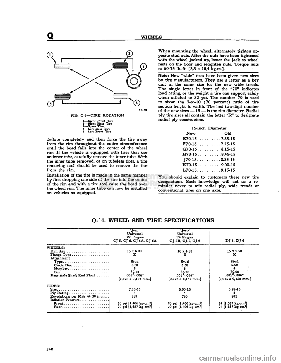
11463
FIG.
Q-9—TIRE
ROTATION
1—
Right
Front
Tire
2—
Right
Rear
Tire
3—
Spare
Tire
4—
-Left
Rear
Tire
5—
Left
Front
Tire
deflate completely and then force the tire away
from
the rim throughout the entire circumference
until
the bead falls into the center of the wheel
rim.
If the vehicle is equipped with tires that use
an
inner tube, carefully remove the inner tube.
With
the inner tube removed, or on tubeless tires, a tire
removing tool should be used to remove the tire
from
the rim.
Installation
of the tire is made in the same manner
by first dropping one side of the tire into the center
of the rim and with a tire tool raise the bead over
the wheel
rim.
The inner tube can now be installed
on vehicles so equipped.
When
mounting the wheel, alternately tighten op
posite stud nuts. After the nuts have been tightened
with
the wheel jacked up, lower the
jack
so wheel rests on the floor and retighten nuts. Torque nuts
to 60-75 lb.-ft. [8,3 a 10,4 kg-m.].
Note:
New "wide" tires have been given new sizes
by tire manufacturers. They use a letter as a key
unit
in the name size for the new wide treads.
The
single letter in front of the "70" indicates load rating, or the weight a tire can support safely
when inflated to 32 psi. The number 70 is used to show the
7-to-10
(70 percent) ratio of tire section height to width. The last two-digit number of the new sizes— 15 —
is
the rim diameter.
Radial
ply
tire sizes all contain the letter
"R"
to designate
radial
ply construction.
15-inch
Diameter
New Old
E70-15
7.35-15
F70-15
.7.75-15
G70-15
8.15-15
H70-15
8.45-15
J70-15
.8.85-15
K70-15
. .... .9.00-15
L70-15
9.15-15
You
should explain to customers
these
new tire
designations. Such knowledge
will
act as a re
minder
never to mix
radial
ply, wide treads or
conventional tires on one axle.
0-14.
WHEEL
AND
TIRE
SPECIFICATIONS
'Jeep'
Universal
V6
Engine
CJ-5,
CJ-6,
CJ-5A,
CJ-6A
'Jeep*
Universal
F4
Engine
CJ-3B,
CJ-5,
CJ-6
DJ-5,
DJ-6
WHEELS:
Rim
Size 15 x
6.00
16 x 4.50
15 x 5.50
K
E
K
Attachment
Type
Stud
Stud Stud
Circle
Dia 5.50 5.50 5.50
5 5
4
Size
H-20
H-20
H-20
Rear
Axle Shaft End Float .001*-.006"
.001"-.006" .001 *-.006"
[0 ,025 a 0,152 mm.)
[0,025 a 0,152 mm.] [0,025 a 0,152 mm.]
TIRES:
Size.
7.35-15
6.00-16
6.85-15
Ply
Rating 4
4 2
Revolutions per Mile @ 30 mph.. . 781 730 803
Inflation
Pressure
Front
20
psi
[1,406 kg-cm2]
20 psi [1,406 kg-cm2] 24 [1,687 kg-cm*]
Rear
24
psi
[1,687 kg-cm*]
20 psi [1,406 kg-cm2] 24 [1,687 kg-cm*] 340
Page 341 of 376
'Jeep'
UNIVERSAL
SERIES
SERVICE
MANUAL
R
FRAME
Contents
SUBJECT
PAR.
Draw
Bar
R-6
Frame
Alignment
.R-2
Frame
Dimensions
.R-3
Front
Axle Alignment.
R-5
Straightening
Frame
R-4
R-1.
GENERAL
equipped with V6 engines, refer
to
measurements
The
frame
is the
structural center
of
the vehicle,
B£?wn
in
FiB-
R"f
, _ , r' .
for in addition
to
carrying
the load,
it
provides and The inost convenient method
of
making this check,
maintains
correct relationship
between
other units
Particularly
when
the
body
is on the
chassis,
is by
to assure their normal functioning. marking
on the
floor
all
dimensional points from
Of
rugged design, the frame
is
constructed of heavy
fhlch
measurements should
be
taken.
This
is
channel
steel side
rails
and cross-members.
Brack-
known
a\
Plumb-bobbing
the
frame Select
a
ets and diagonal braces
are
used
to
maintain
the
?Pace
on the
floof
^hlch
»
extr«nely
level If
work-
proper
longitudinal position
of the
side
rails
rela-
ing Pn
a.,fPen^
c*ean
* s°
that
the fha*k
tive
to
each other, and
at the
same time provide
*****
Jl!*
be
vJs.lble
underneath
the
frame
to be
additional
resistance
to
torsional strains. Fig. R-1, checked
If
workmg
on a
wooden
floor
it is ad-
R-2,
and R-3 illustrate
the
subject models. disable
la^
f f * V
Underneath
*he ve"
Vehicles
that have been
in an
accident
of any
hide
and
carefully tack them
m
place. Drop
a
nature,
which
may
result
in a
swayed
or
sprung gumb-bob from each point indicated
in
Figures
frame,
should always
be
carefully checked
for ^
an?
L'maJkl?g the uflo?r
Meetly underneath
proper
frame alignment, steering geometry,
and the
point. Satisfactory checking depends entirely
axle alignment.
on the
accuracy
of the
marks
in
relation
to the
frame.
To
check points that have been marked, carefully
move
the vehicle away from the layout on the floor,
R-2.
Checking
Frame
Alignment
anci
proceed
as
follows:
The
most efficient
and
satisfactory method
of a.
Check
the
frame
at
front
and
rear
end
using
checking
frame alignment
is
with
a
frame aligning corresponding marks
on the
floor.
If
widths
cor-
fixture
which
is
equipped with bending
tools
for
respond
to
frame specifications, draw
a
center line
straightening frame parts. In the absence
of
such
a the
full
length
of
the vehicle, halfway
between
the
fixture,
frame
alignment
may be
determined
by
marks indicating front and
rear
widths.
If
frame
using the
"X"
or diagonal method of checking from width
is not
correct and
the
center line cannot
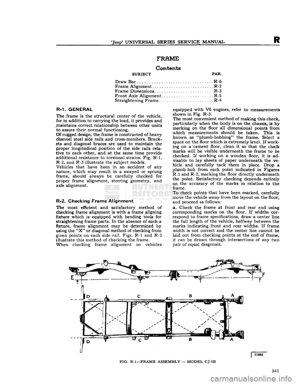
be
given points
on
each side
rail.
Figs.
R-1 and R-2
laid
out
from checking points
at the
end
of
frame,
illustrate
this method
of
checking
the
frame.
it
can
be
drawn through intersections
of
any
two
When
checking frame alignment
on
vehicles
pair
of
equal diagonals.
FIG.
R-1—FRAME
ASSEMBLY
—
MODEL
CJ-3B
341
Page 343 of 376
'Jeep*
UNIVERSAL
SERIES
SERVICE
MANUAL
R
frame.
This
could cause the already aligned sec
tions of the frame to
become
misaligned or weak ened.
R-3.
Frame Dimensions
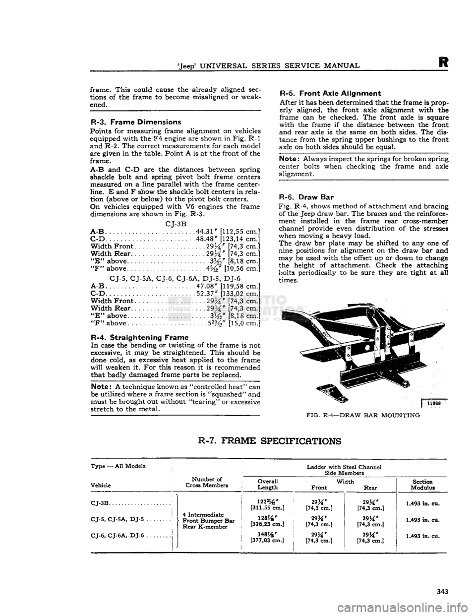
Points for measuring frame alignment on vehicles
equipped with the F4
engine
are shown in
Fig.
R-l
and
R-2.
The correct measurements for each model
are
given in the table. Point A is at the front of the
frame.
A-B
and C-D are the distances
between
spring
shackle
bolt and spring pivot bolt frame centers
measured
on a line parallel with the frame center-
line.
E and F show the shackle bolt centers in
rela
tion (above or below) to the pivot bolt centers.
On
vehicles equipped with V6
engines
the frame dimensions are shown in Fig. R-3.
CJ-3B
A-B
44.31"
[112,55
cm.]
C-D
. . . . . .48.48"
[123,14
cm.]
Width
Front
29%" [74,3 cm.]
Width
Rear
29M" [74,3 cm.]
"E"
above .3W [8,18 cm.]
"F"
above 4%* [10,56 cm.]
CJ-5,
CJ-5A,
CJ-6,
CJ-6A,
DJ-5, DJ-6
A-B
.47.08"
[119,58
cm.]
C-D.
52.37"
[133,02
cm.]
Width
Front
2934"
[74,3 cm.]
Width
Rear
29j|" [74,3 cm.]
"E"
above 3%" [8,18 cm.]
"F"
above. .5%" [15,0 cm.]
R-4.
Straightening Frame
In
case the bending or twisting of the frame is not
excessive, it may be straightened.
This
should be
done
cold, as excessive heat applied to the frame
will
weaken it. For this reason it is recommended that badly damaged frame parts be replaced.
Note:
A technique known as "controlled heat" can
be utilized where a frame section is "squashed" and must be brought out without "tearing" or excessive
stretch
to the metal.
R-5.
Front
Axle
Alignment
After
it has been determined that the frame is prop
erly
aligned, the front axle alignment with the
frame
can be checked. The front axle is square
with
the frame if the distance
between
the front
and
rear
axle is the same on both sides. The dis
tance from the spring upper bushings to the front
axle on both sides should be equal.
Note:
Always inspect the springs for broken spring
center
bolts
when checking the frame and axle
alignment.
R-6. Draw Bar
Fig.
R-4, shows method of attachment and bracing of the Jeep draw bar. The braces and the reinforce
ment installed in the frame
rear
cross-member
channel
provide even distribution of the stresses
when moving a heavy load.
The
draw bar plate may be shifted to any one of
nine positions for alignment on the draw bar and
may
be used with the
offset
up or down to change
the height of attachment.
Check
the attaching
bolts
periodically to be sure they are tight at all
times.
FIG.
R-4—DRAW
BAR
MOUNTING
R-7.
FRflME
SPECIFICATIONS
Type
— All Models j
Ladder
with Steel
Channel
Side
Members
Vehicle
Number
of
Cross
Members
Overall
Length
Width
Front
Rear
Section
Modulus
CJ-3B
i
CJ-5,
CJ-5A,
DJ-5 1
j
4 Intermediate j
•
Front
Bumper Bar
Rear
K-member 122%'
[311,55 cm.]
128%'
[326,23
cm.] 29^*
[74,3 cm.]
[74,3 cm.]
29M'
[74,3 cm.]
[74,3 cm.] 1.493 in. cu.
1.493 in. cu.
CJ-6,
CJ-6A,
DJ-6
|
J
1
I
r
\mw t
[377,03
cm.]
29M'
[74,3 cm.]
29M'
[74,3 cm.] 1.493 in. cu.
343
Page 349 of 376
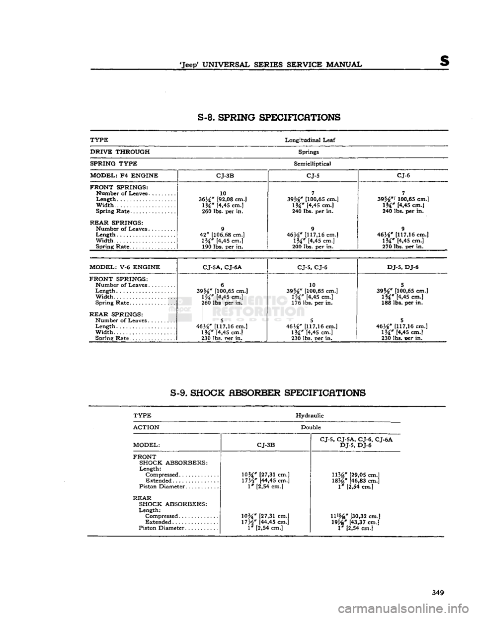
•Jeep'
UNIVERSAL SERIES SERVICE
MANUAL
S-8.
SPRING SPECIFICATIONS
TYPE
Longitudinal
Leaf
DRIVE
THROUGH
Springs
SPRING TYPE
Semielliptical
MODEL;
F4
ENGINE CJ-3B CJ-5 CJ-6
FRONT SPRINGS:
Width...
REAR
SPRINGS:
Width
Spring
Rate
10
3634" [92,08 cm.]
\W
[4,45 cm.]
260 lbs. per in.
9
42"
[106.68 cm.]
l%"
[4,45 cm.] 190 lbs. per in.
7
395**
[100,65 cm.]
1&"
[4,45 cm.]
240 lbs. per in.
9
46J*#
[117,16 cm.]
IW
[4,45 cm.]
200 lbs. per in.
7
395*"'
100,65 cm.]
l%"
[4.45 cm.]
240 lbs. per in.
9
46}*"
1117,16 cm.]
l%"
[4,45 cm.]
270
lbs.
per in.
MODEL:
V-6
ENGINE
C
J-5A, CJ-6 A
CJ-5, CJ-6 DJ-5,
DJ-6
FRONT SPRINGS:
Number
of
Leaves
Width.....
Spring
Rate
REAR
SPRINGS:
Width
Spring
Rate
6
395*"
[100,65 cm.]
1%"
[4,45 cm.]
260 lbs per in.
5
46H"
[117,16 cm.]
\W
K,45
cm.]
230 lbs.
r»er
in. 10
39%"
[100,65 cm.]
IW
[4,45 cm.]
176 lbs. per in.
5
46
H"
[117,16 cm.]
IW
[4,45 cm.]
230 lbs. per in.
5
395**
[100,65 cm.]
1%"
[4,45 cm.]
188 lbs. per in.
5
463*"
[117,16 cm.]
1%"
[4,45 cm.]
230 lbs. t>er in.
S-9.
SHOCK ABSORBER SPECIFICATIONS
TYPE
Hydraulic
ACTION
Double
MODEL:
CJ-3B CJ-5, CJ-5A, CJ-6, CJ-6A
DJ-5,
DJ-6
FRONT SHOCK ABSORBERS:
Length:
"
[27,31 cm.]
Compressed
"
[27,31 cm.]
llj*i"
[29,05 cm.]
Extended
*
[44,45 cm.]
1%W
[46,83 cm.]
Piston Diameter
I" [2,54 cm.]
1* [2,54 cm.]
REAR
SHOCK ABSORBERS:
Length:
Compressed
10H
[27,31 cm.]
11%*
[30,32 cm.]
Extended
17H"
[44,45 cm.]
19j*j"
[43,37 cm.]
Piston Diameter
1"
[2,54 cm.] 1" [2,54 cm.]
349