hood release JEEP DJ 1953 Service Manual
[x] Cancel search | Manufacturer: JEEP, Model Year: 1953, Model line: DJ, Model: JEEP DJ 1953Pages: 376, PDF Size: 19.96 MB
Page 7 of 376

'Jeep*
UNIVERSAL SERIES
SERVICE
MANUAL
B
LUBRICATION
AND
PERIODIC SERVICES
Contents
PAR. SUBJECT
PAR.
SUBJECT
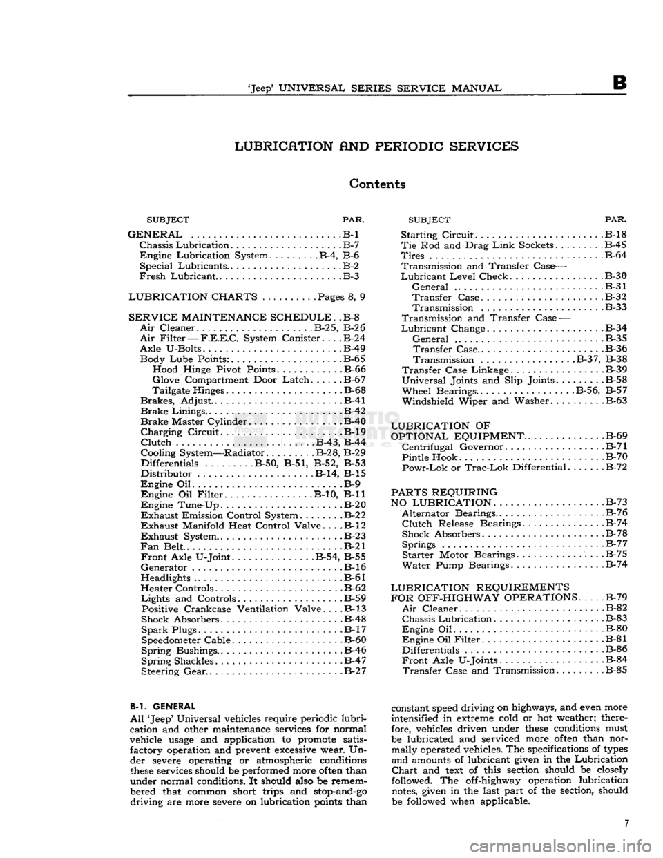
GENERAL
.B-l
Chassis
Lubrication
B-7
Engine
Lubrication System B-4, B-6
Special
Lubricants B-2
Fresh
Lubricant.
.B-3
LUBRICATION CHARTS
. Pages 8, 9
SERVICE
MAINTENANCE SCHEDULE.
.B-8
Air
Cleaner
B-2
5,
B-2
6
Air
Filter
—
F.E.E.C.
System Canister
B-2
4
Axle
U-Bolts B-49 Body
Lube
Points: B-65 Hood Hinge Pivot Points B-66
Glove
Compartment Door
Latch
B-6
7
Tailgate Hinges .B-68
Brakes,
Adjust .B-41
Brake
Linings .B-42
Brake
Master Cylinder B-40
Charging
Circuit
B-l9
Clutch
. B-43, B-44
Cooling System—Radiator. B-28, B-29 Differentials
........
.B-50, B-51, B-52, B-53
Distributor
B-14, B-l5
Engine
Oil B-9
Engine
Oil
Filter
B-10, B-ll
Engine
Tune-Up B-20
Exhaust
Emission Control System
B-2
2
Exhaust
Manifold Heat Control Valve. . . .B-l2
Exhaust
System
B-2 3
Fan
Belt . .B-21
Front
Axle U-Joint B-54, B-55
Generator
.B-16
Headlights B-61
Heater Controls B-62
Lights
and Controls B-59 Positive Crankcase Ventilation Valve. . . .B-l3
Shock Absorbers B-48
Spark
Plugs. B-17
Speedometer Cable. .B-60
Spring
Bushings.. . .B-46
Spring
Shackles .B-47
Steering
Gear
B-2 7
B-l. GENERAL
All
'Jeep' Universal vehicles require periodic
lubri
cation and other maintenance services for normal
vehicle
usage
and application to promote satis factory operation and prevent
excessive
wear. Un
der severe operating or atmospheric conditions
these
services should be performed more
often
than
under normal conditions. It should also be remem
bered that common short trips and
stop-and-go
driving
are more severe on lubrication
points
than
Starting
Circuit
B-l8
Tie
Rod and Drag
Link
Sockets
.
B-45
Tires
B-64
Transmission
and Transfer Case—
Lubricant
Level
Check B-30
General
B-31
Transfer
Case B-32
Transmission
.B-33
Transmission
and Transfer
Case
—
Lubricant
Change .B-34
General
.B-35
Transfer
Case B-36
Transmission
B-3
7, B-38
Transfer
Case Linkage B-39
Universal
Joints and Slip Joints.
.......
.B-58
Wheel
Bearings..
.........
. . .B-56, B-57
Windshield
Wiper and Washer B-63
LUBRICATION
OF
OPTIONAL EQUIPMENT
B-69
Centrifugal
Governor. .B-71
Pintle Hook .B-70
Powr-Lok
or
Trac-Lok
Differential B-72
PARTS REQUIRING
NO LUBRICATION.
. . .B-73
Alternator
Bearings. B-76
Clutch
Release Bearings.
.............
.B-74
Shock Absorbers B-78
Springs
B-7
7
Starter
Motor Bearings B-75
Water
Pump Bearings B-74
LUBRICATION REQUIREMENTS FOR OFF-HIGHWAY OPERATIONS
B-79
Air
Cleaner B-82
Chassis
Lubrication
B-83
Engine
Oil B-80
Engine
Oil
Filter
B-81
Differentials .B-86
Front
Axle U-Joints. B-84
Transfer
Case and Transmission .B-85
constant
speed
driving on highways, and even more
intensified in extreme cold or hot weather; there fore, vehicles driven under
these
conditions must
be lubricated and serviced more
often
than nor mally operated vehicles. The specifications of
types
and
amounts of lubricant given in the Lubrication
Chart
and
text
of this section should be closely
followed. The off-highway operation lubrication
notes,
given in the last part of the section, should
be followed when applicable. 7
Page 79 of 376

'Jeep*
UNIVERSAL SERIES SERVICE
MANUAL
Dl
12710
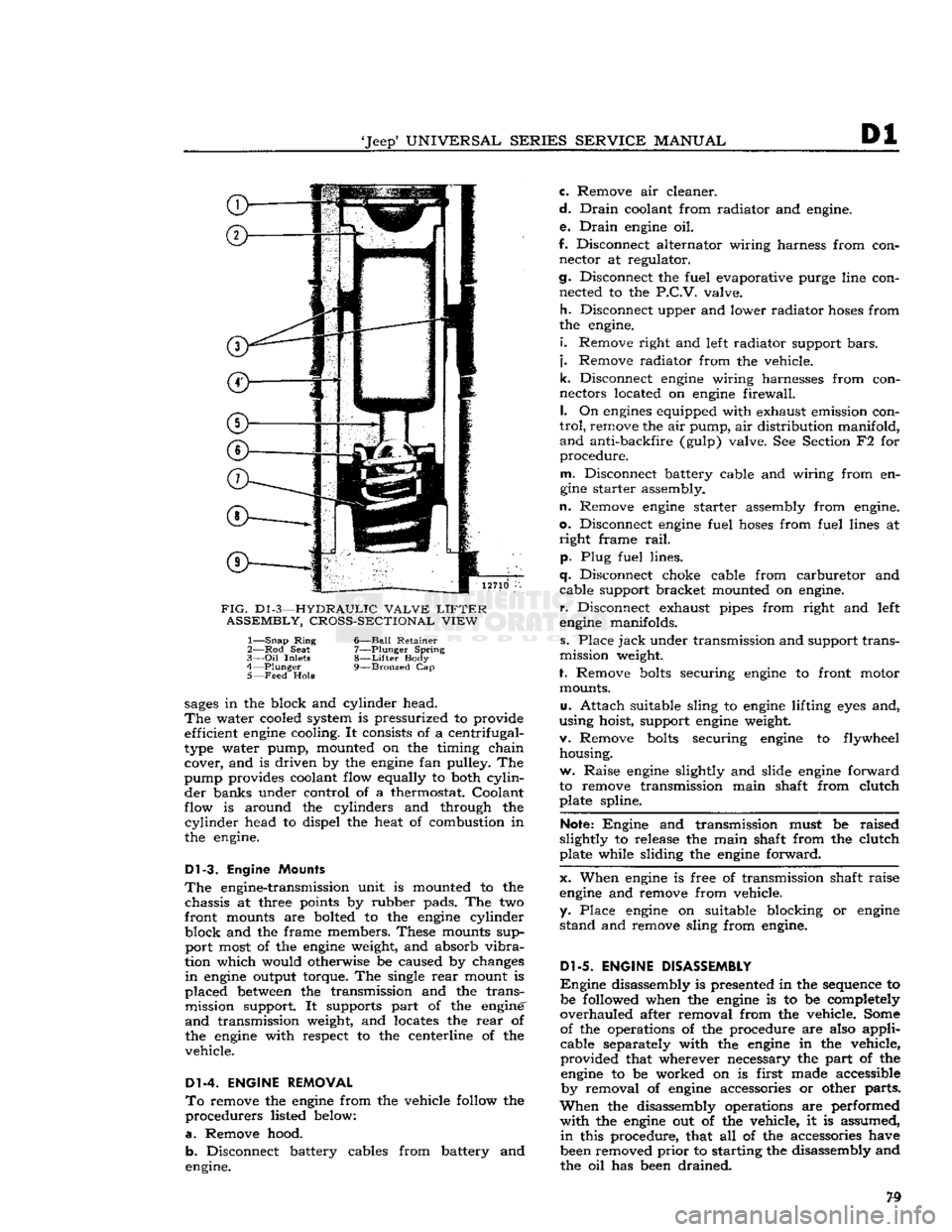
FIG.
D1
-3—HYDRAULIC VALVE
LIFTER
ASSEMBLY, CROSS-SECTIONAL VIEW
1—
Snap
Ring
6—Ball Retainer
2— Rod
Seat
7—Plunger Spring
3—
Oil
Inlets
8—Lifter
Body
4—
Plunger
9—Bronzed
Cap
5— Feed
Hole
sages
in the block and cylinder head.
The
water cooled system is pressurized to provide efficient
engine
cooling. It consists of a centrifugal-
type water pump, mounted on the timing chain cover, and is driven by the
engine
fan pulley. The
pump provides coolant flow equally to both
cylin
der banks under control of a thermostat. Coolant
flow is around the cylinders and through the
cylinder
head to dispel the heat of combustion in
the engine.
Dl-3.
Engine Mounts
The
engine-transmission unit is mounted to the chassis at three points by rubber pads. The two
front mounts are bolted to the
engine
cylinder
block and the frame members. These mounts sup port most of the
engine
weight, and absorb
vibra
tion which would otherwise be caused by changes
in
engine
output torque. The single
rear
mount is
placed
between
the transmission and the trans mission support. It supports part of the engine'
and
transmission weight, and locates the
rear
of
the
engine
with respect to the centerline of the
vehicle.
Dl-4. ENGINE REMOVAL
To
remove the
engine
from the vehicle follow the
procedurers listed below:
a.
Remove hood. b. Disconnect battery cables from battery and
engine. c. Remove air cleaner.
d.
Drain
coolant from radiator and engine.
e.
Drain
engine
oil.
f. Disconnect alternator wiring harness from con nector at regulator.
cj.
Disconnect the fuel evaporative purge line con nected to the
P.C.V.
valve.
h.
Disconnect upper and lower radiator
hoses
from
the engine.
i.
Remove right and left radiator support
bars,
j.
Remove radiator from the vehicle.
k.
Disconnect
engine
wiring harnesses from con
nectors located on
engine
firewall.
I.
On
engines
equipped with exhaust emission con
trol,
remove the air pump, air distribution manifold,
and
anti-backfire (gulp) valve. See Section F2 for
procedure.
m.
Disconnect battery cable and wiring from en
gine
starter assembly.
n.
Remove
engine
starter assembly from engine,
o.
Disconnect
engine
fuel
hoses
from fuel lines at
right
frame
rail,
p. Plug fuel lines.
q.
Disconnect choke cable from carburetor and cable support bracket mounted on engine,
r.
Disconnect exhaust pipes from right and left
engine
manifolds.
s. Place
jack
under transmission and support trans
mission weight.
f. Remove
bolts
securing
engine
to front motor mounts.
u.
Attach suitable sling to
engine
lifting
eyes
and,
using hoist, support
engine
weight.
v. Remove
bolts
securing
engine
to flywheel housing.
w. Raise
engine
slightly and slide
engine
forward
to remove transmission main shaft from clutch plate spline.
Note:
Engine and transmission must be raised
slightly to release the main shaft from the clutch
plate while sliding the
engine
forward.
x. When
engine
is free of transmission shaft raise
engine
and remove from vehicle,
y. Place
engine
on suitable blocking or
engine
stand and remove sling from engine.
Dl-5.
ENGINE DISASSEMBLY
Engine
disassembly is presented in the sequence to be followed when the
engine
is to be completely
overhauled after removal from the vehicle. Some of the operations of the procedure are also applicable separately with the
engine
in the vehicle,
provided that wherever necessary the part of the
engine
to be worked on is first made accessible by removal of
engine
accessories or other parts.
When
the disassembly operations are performed
with
the
engine
out of the vehicle, it is assumed,
in
this procedure, that all of the accessories have
been removed
prior
to starting the disassembly and
the oil has been drained.