tire type JEEP GLADIATOR 2023 Owners Manual
[x] Cancel search | Manufacturer: JEEP, Model Year: 2023, Model line: GLADIATOR, Model: JEEP GLADIATOR 2023Pages: 448, PDF Size: 17.37 MB
Page 9 of 448

7
TOWING A DISABLED VEHICLE .......................... 350 Four–Wheel Drive Models ............................ 351
Without The Key Fob ..................................... 351
Emergency Tow Hooks —
If Equipped .................................................... 351
ENHANCED ACCIDENT RESPONSE SYSTEM
(EARS) .................................................................. 352
EVENT DATA RECORDER (EDR) ......................... 352
SERVICING AND MAINTENANCE
SCHEDULED SERVICING — GASOLINE
ENGINE ................................................................. 353
Maintenance Plan ......................................... 354
SCHEDULED SERVICING — DIESEL ENGINE .... 357
Maintenance Plan — Diesel Fuel Up To
B5 Biodiesel................................................... 358Additional Maintenance — B6 To B20
Biodiesel ........................................................ 361
ENGINE COMPARTMENT .................................... 362
3.6L Gasoline Engine ................................... 3623.0L Diesel Engine ........................................ 363
Checking Oil Level ......................................... 364
Adding Washer Fluid ..................................... 364
Maintenance-Free Battery ............................ 364
Pressure Washing ......................................... 365 VEHICLE MAINTENANCE..................................... 365
Engine Oil ....................................................... 365
Engine Oil Filter ............................................. 366Engine Air Cleaner Filter ............................... 366
Draining Fuel/Water Separator Filter —
Diesel Engine ................................................. 368
Fuel Filter Replacement — Diesel Engine .... 369
Priming If The Engine Has Run Out Of
Fuel — Diesel Engine .................................... 370
Intervention Regeneration Strategy —
Message Process Flow ................................ 371Diesel Exhaust Fluid ..................................... 371
Accessory Drive Belt Inspection ................... 372Air Conditioner Maintenance........................ 372
Body Lubrication ........................................... 374Windshield Wiper Blades.............................. 374Exhaust System ............................................ 376
Cooling System .............................................. 377
Charge Air Cooler — Inter-Cooler
(Diesel Engine) .............................................. 379
Brake System ............................................... 380
Front/Rear Axle Fluid ................................... 380Transfer Case ............................................... 381
Manual Transmission — If Equipped............ 381
Automatic Transmission —
If Equipped .................................................... 381
Fuses ............................................................. 382Bulb Replacement ........................................ 392 TIRES ..................................................................... 395
Tire Safety Information ................................. 395
Tires — General Information ......................... 401
Tire Types....................................................... 405Spare Tires — If Equipped ............................ 406
Wheel And Wheel Trim Care......................... 407
Snow Traction Devices ................................. 408
Tire Rotation Recommendations ................. 409
DEPARTMENT OF TRANSPORTATION
UNIFORM TIRE QUALITY GRADES .................... 410
Treadwear...................................................... 410
Traction Grades ............................................. 410Temperature Grades..................................... 410
STORING THE VEHICLE ....................................... 411
BODYWORK .......................................................... 411
Protection From Atmospheric Agents .......... 411
Body And Underbody Maintenance ............. 412
Preserving The Bodywork ............................. 412
INTERIORS ........................................................... 414
Carpet Safety Information ............................ 414
Carpet Removal............................................. 415Seats And Fabric Parts ................................. 416
Plastic And Coated Parts .............................. 417
Leather Surfaces........................................... 417
Glass Surfaces ............................................. 417
23_JT_OM_EN_USC_t.book Page 7
Page 12 of 448
10
SYMBOLS KEY
If you do not read the entire Owner’s Manual, you may miss important
information. Observe all Cautions and Warnings.
ROLLOVER WARNING
Utility vehicles have a significantly higher rollover rate than other types of
vehicles. This vehicle has a higher ground clearance and a higher center of
gravity than many passenger vehicles. It is capable of performing better in a
wide variety of off-road applications. Driven in an unsafe manner, all vehicles
can go out of control. Because of the higher center of gravity, if this vehicle is
out of control it may roll over while some other vehicles may not.
Do not attempt sharp turns, abrupt maneuvers, or other unsafe driving actions
that can cause loss of vehicle control. Failure to operate this vehicle safely may
result in a collision, rollover of the vehicle, and severe or fatal injury. Drive
carefully.
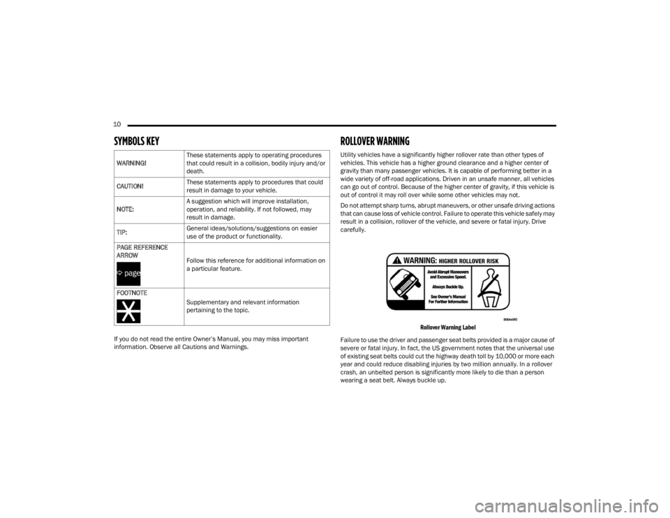
Rollover Warning Label
Failure to use the driver and passenger seat belts provided is a major cause of
severe or fatal injury. In fact, the US government notes that the universal use
of existing seat belts could cut the highway death toll by 10,000 or more each
year and could reduce disabling injuries by two million annually. In a rollover
crash, an unbelted person is significantly more likely to die than a person
wearing a seat belt. Always buckle up.
WARNING!
These statements apply to operating procedures
that could result in a collision, bodily injury and/or
death.
CAUTION! These statements apply to procedures that could
result in damage to your vehicle.
NOTE: A suggestion which will improve installation,
operation, and reliability. If not followed, may
result in damage.
TIP: General ideas/solutions/suggestions on easier
use of the product or functionality.
PAGE REFERENCE
ARROW
Follow this reference for additional information on
a particular feature.
FOOTNOTE Supplementary and relevant information
pertaining to the topic.
23_JT_OM_EN_USC_t.book Page 10
Page 140 of 448
138GETTING TO KNOW YOUR INSTRUMENT PANEL
AdBlue® (UREA) Injection System Failure
Warning Light — If Equipped
This warning light will illuminate along
with a dedicated message on the display
(if equipped) if an unknown fluid not
conforming with acceptable
characteristics is inserted, or if an average
consumption of AdBlue® (UREA) over 50% is
detected. Contact an authorized dealer as soon as
possible. If the problem is not solved, a specific message will
appear on the Instrument Cluster Display
whenever a certain threshold is reached until it will
no longer be possible to start the engine.
When about 125 miles (200 km) are remaining
before the AdBlue® (UREA) tank is empty, a
continuous dedicated message will appear on the
instrument panel, accompanied by a buzzer sound
(if equipped).
YELLOW INDICATOR LIGHTS
4WD Indicator Light — If Equipped
This light alerts the driver that the vehicle
is in the four-wheel drive mode, and the
front and rear driveshafts are
mechanically locked together forcing the
front and rear wheels to rotate at the same speed.
4WD Low Indicator Light — If Equipped
This light alerts the driver that the vehicle
is in the 4WD Low mode. The front and
rear driveshafts are mechanically locked
together forcing the front and rear
wheels to rotate at the same speed. Low range
provides a greater gear reduction ratio to provide
increased torque at the wheels.
4WD Part Time Indicator Light —
If Equipped
This light alerts the driver that the vehicle
is in the four-wheel drive part time mode,
and the front and rear driveshafts are
mechanically locked together forcing the
front and rear wheels to rotate at the same speed.
Axle Locker Fault Indicator Light —
If Equipped
This light indicates when front and/or
rear axle locker fault has been detected.
Rear Axle Lock Indicator Light —
If Equipped
This light indicates when the rear axle
lock has been activated Ú page 161.
Front And Rear Axle Lock Indicator Light —
If Equipped
This light indicates when the front, rear,
or both axles have been locked. The
telltale will display the lock icon on the
front and rear axles to indicate the
current lock status.
CAUTION!
The TPMS has been optimized for the original
equipment tires and wheels. TPMS pressures
and warning have been established for the tire
size equipped on your vehicle. Undesirable
system operation or sensor damage may result
when using replacement equipment that is not
of the same size, type, and/or style. Aftermarket
wheels can cause sensor damage. Using
aftermarket tire sealants may cause the Tire
Pressure Monitoring System (TPMS) sensor to
become inoperable. After using an aftermarket
tire sealant it is recommended that you take
your vehicle to an authorized dealer to have your
sensor function checked.
23_JT_OM_EN_USC_t.book Page 138
Page 164 of 448
162STARTING AND OPERATING
4L
Four-Wheel Drive Low Range — This range provides
low speed four-wheel drive. It maximizes torque to
the front driveshaft, forcing the front and rear
wheels to rotate at the same speed. This range
provides additional traction and maximum pulling
power for loose, slippery road surfaces only. Do not
exceed 25 mph (40 km/h).
The transfer case is intended to be driven in the 2H
position for normal street and highway conditions,
such as hard-surfaced roads.
In the event that additional traction is required, the
transfer case 4H and 4L positions can be used to
lock the front and rear driveshafts together, forcing
the front and rear wheels to rotate at the same
speed. The 4H and 4L positions are intended for
loose, slippery road surfaces only and not intended
for normal driving. Driving in the 4H and 4L
positions on hard-surfaced roads will cause
increased tire wear and damage to the driveline
components. For further information on shifting
into 4H or 4L Ú page 162.
The instrument cluster alerts the driver that the
vehicle is in four-wheel drive, and the front and
rear driveshafts are locked together. The light will
illuminate when the transfer case is shifted into
the 4H position.
When operating your vehicle in 4L, the engine
speed will be approximately three times (four times
for Rubicon models) that of the 2H or 4H positions at a given road speed. Take care not to overspeed
the engine.
Proper operation of four-wheel drive vehicles
depends on tires of equal size, type, and
circumference on each wheel. Any difference will
adversely affect shifting and cause damage to the
transfer case.
Because four-wheel drive provides improved
traction, there is a tendency to exceed safe turning
and stopping speeds. Do not go faster than road
conditions permit.
Shifting Procedures
2H TO 4H OR 4H TO 2H
Shifting between 2H and 4H can be made with the
vehicle stopped or in motion. The preferred shifting
speed would be 0 to 45 mph (72 km/h). With the
vehicle in motion, the transfer case will engage/
disengage faster if you momentarily release the
accelerator pedal after completing the shift. Do not
accelerate while shifting the transfer case. Apply a
constant force when shifting the transfer case lever.
NOTE:
Do not attempt to make a shift while only the
front or rear wheels are spinning. The front and
rear driveshaft speeds must be equal for the
shift to take place. Shifting while only the front
or rear wheels are spinning can cause damage
to the transfer case.
Delayed shifts out of four-wheel drive may be
experienced due to uneven tire wear, low or
uneven tire pressures, excessive vehicle
loading, or cold temperatures.
Shifting effort will increase with speed, this is
normal.
During cold weather, you may experience
increased effort in shifting until the transfer case
fluid warms up. This is normal.
4H TO 4L OR 4L TO 4H
With the vehicle rolling at 1 to 3 mph (2 to 5 km/h),
shift an automatic transmission into NEUTRAL (N), or
press the clutch pedal on a manual transmission.
While the vehicle is coasting at 1 to 3 mph (2 to
5 km/h), shift the transfer case lever firmly to the
desired position. Do not pause with the transfer case
in N (Neutral). Once the shift is completed, place the
automatic transmission into DRIVE or release the
clutch pedal on a manual transmission.
NOTE:Shifting into or out of 4L is possible with the vehicle
completely stopped; however, difficulty may occur
due to the mating teeth not being properly aligned.
Several attempts may be required for clutch teeth
alignment and shift completion to occur. The
preferred method is with the vehicle rolling at 1 to
3 mph (2 to 5 km/h). Avoid attempting to engage
or disengage 4L with the vehicle moving faster
than 1 to 3 mph (2 to 5 km/h).
23_JT_OM_EN_USC_t.book Page 162
Page 166 of 448
164STARTING AND OPERATING
For variable driving conditions, the 4H AUTO mode
can be used. In this mode, the front axle is
engaged, but the vehicle's power is sent to the rear
wheels. Four-wheel drive will be automatically
engaged when the vehicle senses a loss of
traction. Because the front axle is engaged, this
mode will result in lower fuel economy than the 2H
mode.
In the event that additional traction is required, the
transfer case 4H and 4L positions can be used to
lock the front and rear driveshafts together, forcing
the front and rear wheels to rotate at the same
speed. The 4H and 4L positions are intended for
loose, slippery road surfaces only and not intended
for normal driving. Driving in the 4H and 4L
positions on hard-surfaced roads will cause
increased tire wear and damage to the driveline
components. For further information on shifting
into 4H or 4L Ú page 164.
The instrument cluster alerts the driver that the
vehicle is in four-wheel drive, and the front and
rear driveshafts are locked together. The light will
illuminate when the transfer case is shifted into
the 4H position.
When operating your vehicle in 4L, the engine
speed will be approximately three times (four times
for Rubicon models) that of the 2H or 4H positions
at a given road speed. Take care not to overspeed
the engine. Proper operation of four-wheel drive vehicles
depends on tires of equal size, type, and
circumference on each wheel. Any difference will
adversely affect shifting and cause damage to the
transfer case.
Because four-wheel drive provides improved
traction, there is a tendency to exceed safe turning
and stopping speeds. Do not go faster than road
conditions permit.
Shifting Procedures
2H TO 4H AUTO OR 4H AUTO TO 2H
Shifting between 2H and 4H AUTO can be made
with the vehicle stopped or in motion. The
preferred shifting speed would be 0 to 45 mph
(72 km/h). With the vehicle in motion, the transfer
case will engage/disengage faster if you
momentarily release the accelerator pedal after
completing the shift. Do not accelerate while
shifting the transfer case. Apply a constant force
when shifting the transfer case lever.
2H/4H AUTO TO 4H PART TIME OR 4H PART
TIME TO 2H/4H AUTO
Shifting between 2H/4H AUTO to 4H PART TIME
can be made with the vehicle stopped or in motion.
The preferred shifting speed would be 0 to 45 mph
(72 km/h). With the vehicle in motion, the transfer
case will engage/disengage faster if you
momentarily release the accelerator pedal after completing the shift. Do not accelerate while
shifting the transfer case. Apply a constant force
when shifting the transfer case lever.
NOTE:
Do not attempt to make a shift while only the
front or rear wheels are spinning. The front and
rear driveshaft speeds must be equal for the
shift to take place. Shifting while only the front
or rear wheels are spinning can cause damage
to the transfer case.
Delayed shifts out of four-wheel drive may be
experienced due to uneven tire wear, low or
uneven tire pressures, excessive vehicle
loading, or cold temperatures.
Shifting effort will increase with speed, this is
normal.
During cold weather, you may experience
increased effort in shifting until the transfer case
fluid warms up. This is normal.
4H PART TIME/4H AUTO TO 4L OR 4L TO 4H
PART TIME/4H AUTO
With the vehicle rolling at 1 to 3 mph (2 to 5 km/h),
shift an automatic transmission into NEUTRAL (N),
or press the clutch pedal on a manual
transmission. While the vehicle is coasting at 1 to
3 mph (2 to 5 km/h), shift the transfer case lever
firmly to the desired position. Do not pause with
the transfer case in N (Neutral). Once the shift is
23_JT_OM_EN_USC_t.book Page 164
Page 199 of 448
STARTING AND OPERATING197
TRAILER TOWING
In this section you will find safety tips and
information on limits to the type of towing you can
reasonably do with your vehicle. Before towing a
trailer, carefully review this information to tow your
load as efficiently and safely as possible.
To maintain the New Vehicle Limited Warranty
coverage, follow the requirements and
recommendations in this manual concerning
vehicles used for trailer towing.
COMMON TOWING DEFINITIONS
The following trailer towing related definitions will
assist you in understanding the following
information:
Gross Vehicle Weight Rating (GVWR)
The GVWR is the total allowable weight of your
vehicle. This includes driver, passengers, cargo
and tongue weight. The total load must be limited
so that you do not exceed the GVWR Ú page 195.
Gross Trailer Weight (GTW)
The GTW is the weight of the trailer plus the weight
of all cargo, consumables and equipment
(permanent or temporary) loaded in or on the trailer
in its "loaded and ready for operation" condition.
The recommended way to measure GTW is to put
your fully loaded trailer on a vehicle scale. The
entire weight of the trailer must be supported by
the scale.
Gross Combination Weight Rating (GCWR)
The GCWR is the total permissible weight of your
vehicle and trailer when weighed in combination.
Gross Axle Weight Rating (GAWR)
The GAWR is the maximum capacity of the front
and rear axles. Distribute the load over the front
and rear axles evenly. Make sure that you do not
exceed either front or rear GAWR Úpage 195.
Tongue Weight (TW)
The TW is the downward force exerted on the hitch
ball by the trailer. You must consider this as part of
the load on your vehicle.
Frontal Area
The frontal area is the maximum height multiplied
by the maximum width of the front of a trailer.
Trailer Sway Control (TSC) — If Equipped
The TSC is a telescoping link that can be installed
between the hitch receiver and the trailer tongue.
It typically provides adjustable friction associated
with the telescoping motion to dampen any
unwanted trailer swaying motions while traveling.
Weight-Carrying Hitch
A weight-carrying hitch supports the trailer tongue
weight, just as if it were luggage located at a hitch
ball or some other connecting point of the vehicle.
These kinds of hitches are commonly used to tow
small and medium sized trailers.
Weight-Distributing Hitch
A Weight-Distributing Hitch system works by
applying leverage through spring (load) bars. They
are typically used for heavier loads to distribute
trailer tongue weight to the tow vehicle's front axle
and the trailer axle(s). When used in accordance
with the manufacturer's directions, it provides for a
more level ride, offering more consistent steering
and brake control thereby enhancing towing
safety. The addition of a friction/hydraulic sway
control also dampens sway caused by traffic and
crosswinds and contributes positively to tow
vehicle and trailer stability. Trailer sway control and
WARNING!
If the gross trailer weight is 2,000 lb (907 kg) or
more, it is recommended to use a weight-
distributing hitch to ensure stable handling of
your vehicle. If you use a standard weight-
carrying hitch, you could lose control of your
vehicle and cause a collision.
WARNING!
It is important that you do not exceed the
maximum front or rear GAWR. A dangerous
driving condition can result if either rating is
exceeded.
4
23_JT_OM_EN_USC_t.book Page 197
Page 204 of 448
202STARTING AND OPERATING
(Continued)
TRAILER AND TONGUE WEIGHT
Never exceed the maximum tongue weight
stamped on your bumper or trailer hitch.
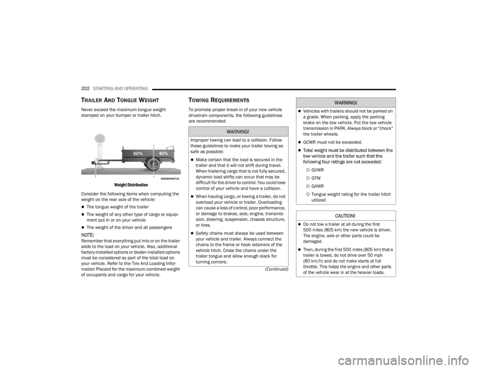
Weight Distribution
Consider the following items when computing the
weight on the rear axle of the vehicle:
The tongue weight of the trailer
The weight of any other type of cargo or equip -
ment put in or on your vehicle
The weight of the driver and all passengers
NOTE:Remember that everything put into or on the trailer
adds to the load on your vehicle. Also, additional
factory-installed options or dealer-installed options
must be considered as part of the total load on
your vehicle. Refer to the Tire And Loading Infor -
mation Placard for the maximum combined weight
of occupants and cargo for your vehicle.
TOWING REQUIREMENTS
To promote proper break-in of your new vehicle
drivetrain components, the following guidelines
are recommended:
WARNING!
Improper towing can lead to a collision. Follow
these guidelines to make your trailer towing as
safe as possible:
Make certain that the load is secured in the
trailer and that it will not shift during travel.
When trailering cargo that is not fully secured,
dynamic load shifts can occur that may be
difficult for the driver to control. You could lose
control of your vehicle and have a collision.
When hauling cargo, or towing a trailer, do not
overload your vehicle or trailer. Overloading
can cause a loss of control, poor performance,
or damage to brakes, axle, engine, transmis -
sion, steering, suspension, chassis structure,
or tires.
Safety chains must always be used between
your vehicle and trailer. Always connect the
chains to the frame or hook retainers of the
vehicle hitch. Cross the chains under the
trailer tongue and allow enough slack for
turning corners.
Vehicles with trailers should not be parked on
a grade. When parking, apply the parking
brake on the tow vehicle. Put the tow vehicle
transmission in PARK. Always block or "chock"
the trailer wheels.
GCWR must not be exceeded.
Total weight must be distributed between the
tow vehicle and the trailer such that the
following four ratings are not exceeded:
GVWR
GTW
GAWR
Tongue weight rating for the trailer hitch
utilized
CAUTION!
Do not tow a trailer at all during the first
500 miles (805 km) the new vehicle is driven.
The engine, axle or other parts could be
damaged.
Then, during the first 500 miles (805 km) that a
trailer is towed, do not drive over 50 mph
(80 km/h) and do not make starts at full
throttle. This helps the engine and other parts
of the vehicle wear in at the heavier loads.
WARNING!
23_JT_OM_EN_USC_t.book Page 202
Page 211 of 448

STARTING AND OPERATING209
additional low speed pulling power is needed.
Vehicle speeds in excess of 25 mph (40 km/h)
should be avoided when in 4L range.
Simultaneous Brake And Throttle
Operation
Many off-road driving conditions require the
simultaneous use of the brake and throttle
(two-footed driving). When climbing rocks, logs, or
other stepped objects, using light brake pressure
with light throttle will keep the vehicle from jerking
or lurching. This technique is also used when you
need to stop and restart a vehicle on a steep
incline.
Driving In Snow, Mud And Sand
SNOW
In heavy snow or for additional control and traction
at slower speeds, shift the transmission into a low
gear and the transfer case into 4L if necessary. Do
not shift to a lower gear than necessary to maintain
headway. Over-revving the engine can spin the
wheels and traction will be lost. If you start to slow
to a stop, try turning your steering wheel no more than a quarter turn quickly back and forth, while
still applying throttle. This will allow the tires to get
fresh traction and help maintain your momentum.
MUD
Deep mud creates a great deal of suction around
the tires and is very difficult to get through. You
should use DRIVE, with the transfer case in the 4L
position to maintain your momentum. If you start to
slow to a stop, try turning your steering wheel no
more than a quarter turn quickly back and forth for
additional traction. Mud holes pose an increased
threat of vehicle damage and getting stuck. They
are normally full of debris from previous vehicles
getting stuck. As a good practice before entering
any mud hole, get out and determine how deep it
is, if there are any hidden obstacles and if the
vehicle can be safely recovered if stuck.
SAND
Soft sand is very difficult to travel through with full
tire pressure. When crossing soft, sandy spots in a
trail, maintain your vehicle's momentum and do
not stop. The key to driving in soft sand is using the
appropriate tire pressure, accelerating slowly, avoiding abrupt maneuvers and maintaining the
vehicle's momentum. If you are going to be driving
on large soft sandy areas or dunes, reduce your
tire pressure to a minimum of 15 psi (103 kPa) to
allow for a greater tire surface area. Reduced tire
pressure will drastically improve your traction and
handling while driving on the soft sand, but you
must return the tires to normal air pressure before
driving on pavement or other hard surfaces. Be
sure you have a way to reinflate the tires prior to
reducing the pressure.
Crossing Obstacles (Rocks And Other High
Points)
While driving off-road, you will encounter many
types of terrain. These varying types of terrain bring
different types of obstacles. Before proceeding,
review the path ahead to determine the correct
approach and your ability to safely recover the
vehicle if something goes wrong. Keeping a firm
grip on the steering wheel, bring the vehicle to a
complete stop and then inch the vehicle forward
CAUTION!
Do not use 4L range when operating the vehicle
on dry pavement. Driveline hardware damage
can result.
CAUTION!
On icy or slippery roads, do not downshift at high
engine RPM or vehicle speeds, because engine
braking may cause skidding and loss of control.
CAUTION!
Reduced tire pressures may cause tire
unseating and total loss of air pressure. To
reduce the risk of tire unseating, while at a
reduced tire pressure, reduce your speed and
avoid sharp turns or abrupt maneuvers.
4
23_JT_OM_EN_USC_t.book Page 209
Page 214 of 448
212STARTING AND OPERATING
IF YOU STALL OR BEGIN TO LOSE HEADWAY
If you stall or begin to lose headway while climbing
a steep hill, allow your vehicle to come to a stop
and immediately apply the brake. Restart the
engine and shift into REVERSE. Back slowly down
the hill allowing engine braking to control the
descent and apply your brakes, if necessary, but
do not allow the tires to lock.
Driving Through Water
Extreme care should be taken crossing any type of
water. Water crossings should be avoided, if
possible, and only be attempted when necessary in
a safe, responsible manner. You should only drive
through areas which are designated and approved.
You should tread lightly and avoid damage to the
environment. You should know your vehicle's
abilities and be able to recover it if something goes wrong. You should never stop or shut a vehicle off
when crossing deep water unless you ingested
water into the engine air intake. If the engine stalls,
do not attempt to restart it. Determine if it has
ingested water first. The key to any crossing is low
and slow. Shift into FIRST gear (manual
transmission), or DRIVE (automatic transmission),
with the transfer case in the 4L position and
proceed very slowly with a constant slow speed
(3 to 5 mph {5 to 8 km/h} maximum) and light
throttle. Keep the vehicle moving; do not try to
accelerate through the crossing. After crossing any
water higher than the bottom of the axle
differentials, you should inspect all of the vehicle
fluids for signs of water ingestion.
BEFORE YOU CROSS ANY TYPE OF WATER
As you approach any type of water, you need to
determine if you can cross it safely and
responsibly. If necessary, get out and walk through
the water or probe it with a stick. You need to be
sure of its depth, approach angle, current and
bottom condition. Be careful of murky or muddy
waters; check for hidden obstacles. Make sure you
will not be intruding on any wildlife, and you can
recover the vehicle if necessary. The key to a safe
crossing is the water depth, current and bottom
conditions. On soft bottoms, the vehicle will sink in,
effectively increasing the water level on the
vehicle. Be sure to consider this when determining
the depth and the ability to safely cross.
CROSSING PUDDLES, POOLS, FLOODED
AREAS OR OTHER STANDING WATER
Puddles, pools, flooded or other standing water
areas normally contain murky or muddy waters.
These water types normally contain hidden
obstacles and make it difficult to determine an
accurate water depth, approach angle, and bottom
condition. Murky or muddy water holes are where
you want to hook up tow straps prior to entering.
This makes for a faster, cleaner and easier vehicle
recovery. If you are able to determine you can
safely cross, than proceed using the low and slow
method.
WARNING!
If the engine stalls or you lose headway or
cannot make it to the top of a steep hill or grade,
never attempt to turn around. To do so may
result in tipping and rolling the vehicle, which
may result in severe injury. Always back carefully
straight down a hill in REVERSE. Never back
down a hill in NEUTRAL using only the vehicle
brakes. Never drive diagonally across a hill,
always drive straight up or down.
CAUTION!
Water ingestion into the axles, transmission,
transfer case, engine or vehicle interior can
occur if you drive too fast or through too deep
of water. Water can cause permanent damage
to engine, driveline or other vehicle compo -
nents, and your brakes will be less effective
once wet and/or muddy.
When driving through water, do not exceed
5 mph (8 km/h). Always check water depth
before entering as a precaution, and check all
fluids afterward. Driving through water may
cause damage that may not be covered by the
New Vehicle Limited Warranty.
23_JT_OM_EN_USC_t.book Page 212
Page 223 of 448

MULTIMEDIA221
Mirrors & Wipers
Blind Spot Alert This setting will change the type of alert provided when an object is detected
in a vehicle’s blind spot. The “Off” setting will turn off Blind Spot Alert. The
“Lights” setting will activate the Blind Spot Alert lights on the outside mirrors.
The “Lights & Chime” setting will activate both the lights on the outside
mirrors and an audible chime.
Hill Start Assist This setting will turn the Hill Start Assist system on or off.
ParkView Backup Camera Active Guidelines This setting will turn the ParkView Backup Camera Active Guidelines on or off.
ParkView Backup Camera Delay This setting will add a timed delay to the ParkView Backup Camera when
shifting out of REVERSE.
Fixed ParkView Backup Camera Guidelines This setting will turn the Fixed ParkView Backup Camera Guidelines on or off.
Front Camera Gridlines This setting will turn the Front Camera Gridlines on or off.
Tire Fill Assist This setting will turn Tire Fill Assist on or off.
Setting NameDescription
When the Mirrors & Wipers button is pressed on the touchscreen, the system displays the option related to the vehicle’s mirrors and wipers.
NOTE:Depending on the vehicle’s options, feature settings may vary.
Setting NameDescription
Headlights With Wipers This setting will turn the headlights on when the wipers are activated.
5
23_JT_OM_EN_USC_t.book Page 221