window JEEP GLADIATOR 2023 User Guide
[x] Cancel search | Manufacturer: JEEP, Model Year: 2023, Model line: GLADIATOR, Model: JEEP GLADIATOR 2023Pages: 448, PDF Size: 17.37 MB
Page 31 of 448
GETTING TO KNOW YOUR VEHICLE29
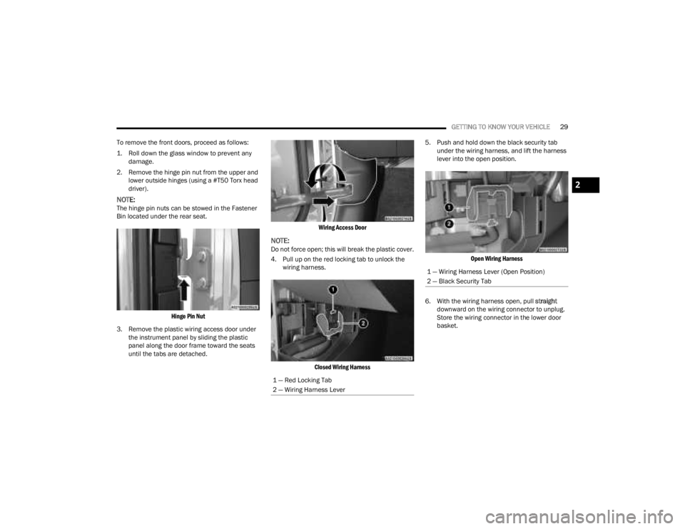
To remove the front doors, proceed as follows:
1. Roll down the glass window to prevent any damage.
2. Remove the hinge pin nut from the upper and lower outside hinges (using a #T50 Torx head
driver).
NOTE:The hinge pin nuts can be stowed in the Fastener
Bin located under the rear seat.
Hinge Pin Nut
3. Remove the plastic wiring access door under the instrument panel by sliding the plastic
panel along the door frame toward the seats
until the tabs are detached.
Wiring Access Door
NOTE:Do not force open; this will break the plastic cover.
4. Pull up on the red locking tab to unlock the
wiring harness.
Closed Wiring Harness
5. Push and hold down the black security tab
under the wiring harness, and lift the harness
lever into the open position.
Open Wiring Harness
6. With the wiring harness open, pull straight
downward on the wiring connector to unplug.
Store the wiring connector in the lower door
basket.
1 — Red Locking Tab
2 — Wiring Harness Lever
1 — Wiring Harness Lever (Open Position)
2 — Black Security Tab
2
23_JT_OM_EN_USC_t.book Page 29
Page 34 of 448
32GETTING TO KNOW YOUR VEHICLE
5. Replace wiring access doors.
NOTE:
When reinstalling the door check arm attachment
screw, screw torque should be between 11.76 ft·lb /
16 N·m and 27.9 ft·lb / 38 N·m.
REAR DOOR REMOVAL
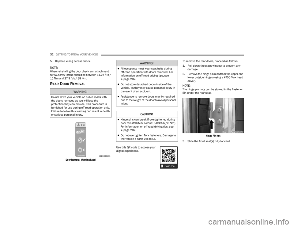
Door Removal Warning Label
Use this QR code to access your
digital experience. To remove the rear doors, proceed as follows:
1. Roll down the glass window to prevent any
damage.
2. Remove the hinge pin nuts from the upper and lower outside hinges (using a #T50 Torx head
driver).
NOTE:The hinge pin nuts can be stowed in the Fastener
Bin under the rear seat.
Hinge Pin Nut
3. Slide the front seat(s) fully forward.WARNING!
Do not drive your vehicle on public roads with
the doors removed as you will lose the
protection they can provide. This procedure is
furnished for use during off-road operation only.
Failure to follow this warning can result in death
or serious personal injury.
WARNING!
All occupants must wear seat belts during
off-road operation with doors removed. For
information on off-road driving tips, see
Ú page 207.
Do not store detached doors inside of the
vehicle, as they may cause personal injury in
the event of an accident.
Assistance to remove doors may by required
due to the weight of the door to avoid personal
injury.
CAUTION!
Hinge pins can break if overtightened during
door reinstall (Max Torque: 5.88 ft·lb / 8 N·m).
For information on off-road driving tips, see
Úpage 207.
Do not overtighten Torx fasteners. Damage to
the vehicle’s parts will occur.
23_JT_OM_EN_USC_t.book Page 32
Page 37 of 448
GETTING TO KNOW YOUR VEHICLE35
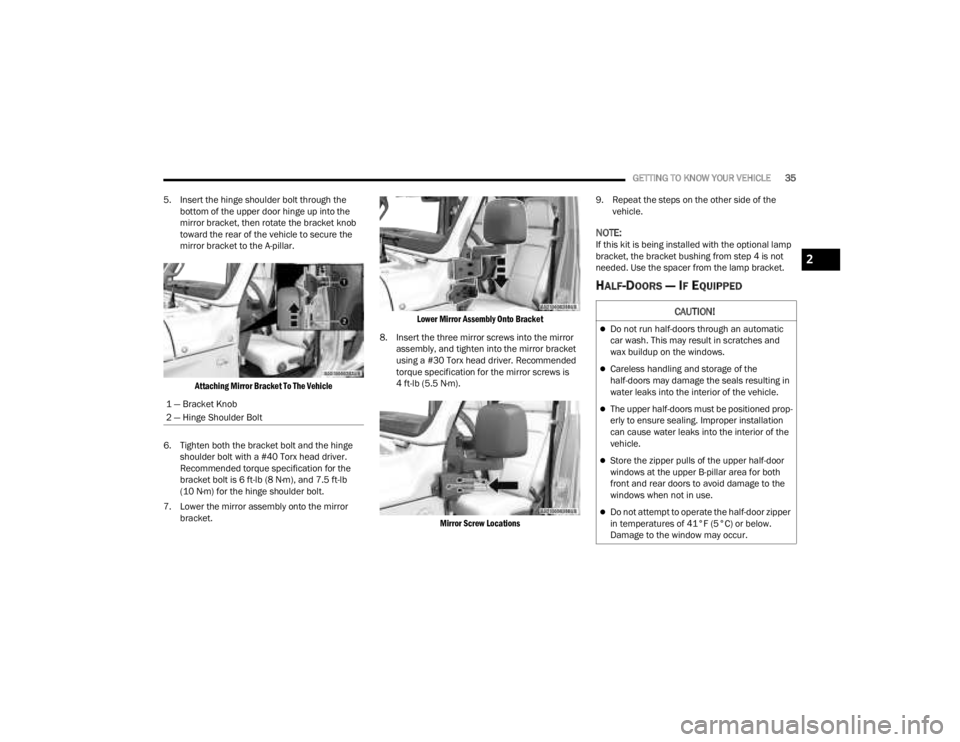
5. Insert the hinge shoulder bolt through the bottom of the upper door hinge up into the
mirror bracket, then rotate the bracket knob
toward the rear of the vehicle to secure the
mirror bracket to the A-pillar.
Attaching Mirror Bracket To The Vehicle
6. Tighten both the bracket bolt and the hinge shoulder bolt with a #40 Torx head driver.
Recommended torque specification for the
bracket bolt is 6 ft-lb (8 N·m), and 7.5 ft-lb
(10 N·m) for the hinge shoulder bolt.
7. Lower the mirror assembly onto the mirror bracket.
Lower Mirror Assembly Onto Bracket
8. Insert the three mirror screws into the mirror assembly, and tighten into the mirror bracket
using a #30 Torx head driver. Recommended
torque specification for the mirror screws is
4 ft-lb (5.5 N·m).
Mirror Screw Locations
9. Repeat the steps on the other side of the
vehicle.
NOTE:If this kit is being installed with the optional lamp
bracket, the bracket bushing from step 4 is not
needed. Use the spacer from the lamp bracket.
HALF-DOORS — IF EQUIPPED
1 — Bracket Knob
2 — Hinge Shoulder Bolt
CAUTION!
Do not run half-doors through an automatic
car wash. This may result in scratches and
wax buildup on the windows.
Careless handling and storage of the
half-doors may damage the seals resulting in
water leaks into the interior of the vehicle.
The upper half-doors must be positioned prop -
erly to ensure sealing. Improper installation
can cause water leaks into the interior of the
vehicle.
Store the zipper pulls of the upper half-door
windows at the upper B-pillar area for both
front and rear doors to avoid damage to the
windows when not in use.
Do not attempt to operate the half-door zipper
in temperatures of 41°F (5°C) or below.
Damage to the window may occur.
2
23_JT_OM_EN_USC_t.book Page 35
Page 39 of 448
GETTING TO KNOW YOUR VEHICLE37
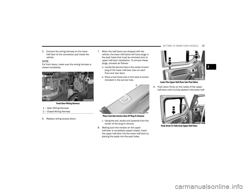
5. Connect the wiring harness on the lower half-door to the connection just inside the
vehicle.
NOTE:For front doors, make sure the wiring harness is
closed completely.
Front Door Wiring Harness
6. Replace wiring access doors. 7. When the half-doors are shipped with the
vehicle, the lower half-doors will have plugs in
the post holes that must be removed prior to
upper half-door installation. To remove these
plugs, proceed as follows:
a. Locate the service hole in the center of each plug of the lower half-door (two on each
front and rear door).
b. Place a tool (hook tool or trim stick is recom -
mended) in the service hole.
Place Tool Into Service Hole Of Plug To Remove
c. Using the tool, slowly pull upwards from the center of the plug to remove.
8. Making sure the window on the upper half-door is completely zipped closed, insert
the upper half-door into the lower half-door by
placing the posts into the post holes.
Lower The Upper Half-Door Into Post Holes
9. Push down firmly on the inside of the upper half-door until it is fully seated in the lower half.
Push Down To Fully Seat Upper Half-Door
1 — Open Wiring Harness
2 — Closed Wiring Harness2
23_JT_OM_EN_USC_t.book Page 37
Page 52 of 448
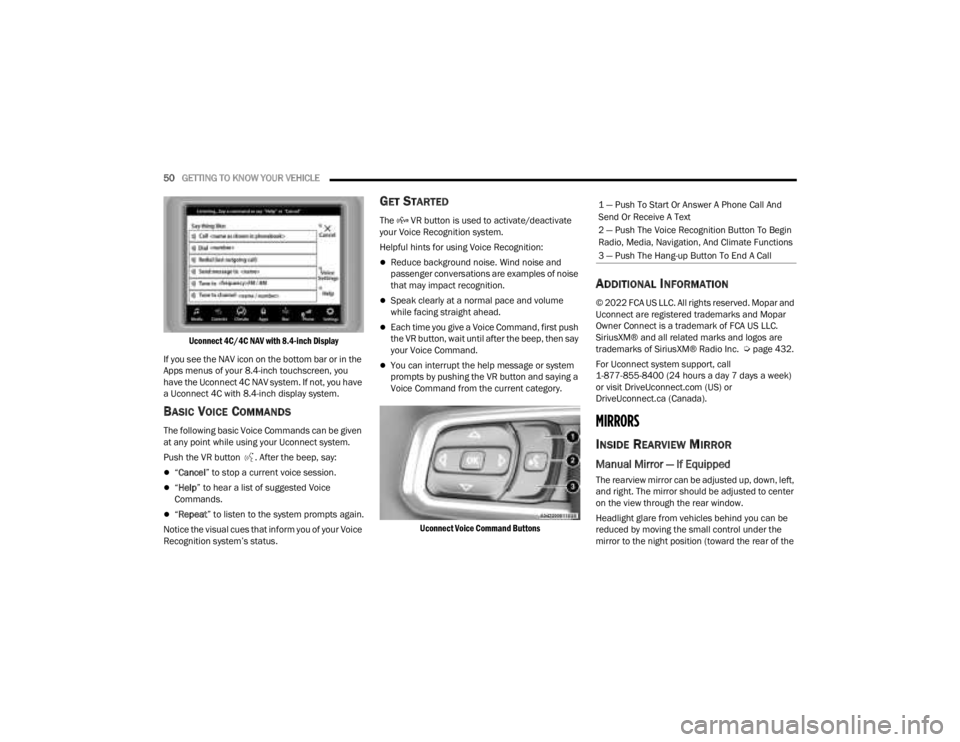
50GETTING TO KNOW YOUR VEHICLE
Uconnect 4C/4C NAV with 8.4-inch Display
If you see the NAV icon on the bottom bar or in the
Apps menus of your 8.4-inch touchscreen, you
have the Uconnect 4C NAV system. If not, you have
a Uconnect 4C with 8.4-inch display system.
BASIC VOICE COMMANDS
The following basic Voice Commands can be given
at any point while using your Uconnect system.
Push the VR button . After the beep, say:
“ Cancel ” to stop a current voice session.
“Help ” to hear a list of suggested Voice
Commands.
“ Repeat ” to listen to the system prompts again.
Notice the visual cues that inform you of your Voice
Recognition system’s status.
GET STARTED
The VR button is used to activate/deactivate
your Voice Recognition system.
Helpful hints for using Voice Recognition:
Reduce background noise. Wind noise and
passenger conversations are examples of noise
that may impact recognition.
Speak clearly at a normal pace and volume
while facing straight ahead.
Each time you give a Voice Command, first push
the VR button, wait until after the beep, then say
your Voice Command.
You can interrupt the help message or system
prompts by pushing the VR button and saying a
Voice Command from the current category.
Uconnect Voice Command Buttons
ADDITIONAL INFORMATION
© 2022 FCA US LLC. All rights reserved. Mopar and
Uconnect are registered trademarks and Mopar
Owner Connect is a trademark of FCA US LLC.
SiriusXM® and all related marks and logos are
trademarks of SiriusXM® Radio Inc. Ú page 432.
For Uconnect system support, call
1-877-855-8400 (24 hours a day 7 days a week)
or visit DriveUconnect.com (US) or
DriveUconnect.ca (Canada).
MIRRORS
INSIDE REARVIEW MIRROR
Manual Mirror — If Equipped
The rearview mirror can be adjusted up, down, left,
and right. The mirror should be adjusted to center
on the view through the rear window.
Headlight glare from vehicles behind you can be
reduced by moving the small control under the
mirror to the night position (toward the rear of the
1 — Push To Start Or Answer A Phone Call And
Send Or Receive A Text
2 — Push The Voice Recognition Button To Begin
Radio, Media, Navigation, And Climate Functions
3 — Push The Hang-up Button To End A Call
23_JT_OM_EN_USC_t.book Page 50
Page 53 of 448
GETTING TO KNOW YOUR VEHICLE51
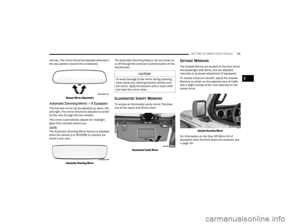
vehicle). The mirror should be adjusted while set in
the day position (toward the windshield).
Manual Mirror Adjustment
Automatic Dimming Mirror — If Equipped
The rearview mirror can be adjusted up, down, left,
and right. The mirror should be adjusted to center
on the view through the rear window.
This mirror automatically adjusts for headlight
glare from vehicles behind you.
NOTE:The Automatic Dimming Mirror feature is disabled
when the vehicle is in REVERSE to improve the
driver’s rear view.
Automatic Dimming Mirror
The Automatic Dimming feature can be turned on
or off through the Uconnect Controls button on the
touchscreen.
ILLUMINATED VANITY MIRRORS
To access an illuminated vanity mirror, flip down
one of the visors and lift the cover.
Illuminated Vanity Mirror
OUTSIDE MIRRORS
The Outside Mirrors are located on the front driver
and passenger side doors, and are adjusted
manually or by power adjustment (if equipped).
To receive maximum benefit, adjust the Outside
Mirror(s) to center on the adjacent lane of traffic
with a slight overlap of the view obtained on the
inside mirror.
Outside Rearview Mirror
For information on the Door Off Mirror Kit (if
equipped) when the front doors are removed, see
Ú page 34.
CAUTION!
To avoid damage to the mirror during cleaning,
never spray any cleaning solution directly onto
the mirror. Apply the solution onto a clean cloth
and wipe the mirror clean.2
23_JT_OM_EN_USC_t.book Page 51
Page 54 of 448
52GETTING TO KNOW YOUR VEHICLE
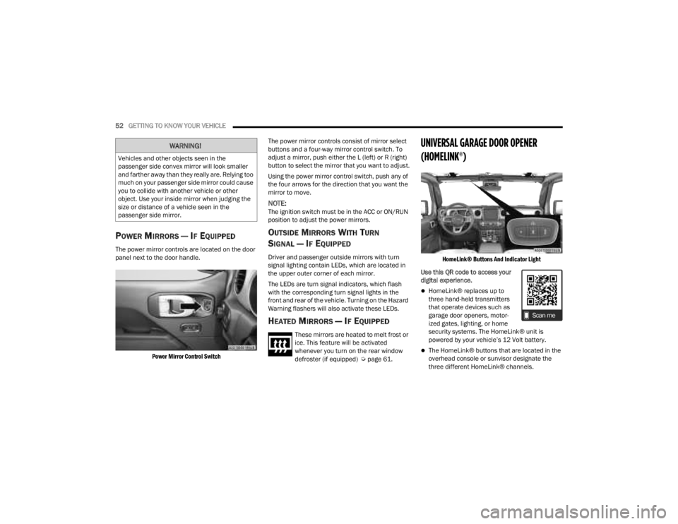
POWER MIRRORS — IF EQUIPPED
The power mirror controls are located on the door
panel next to the door handle.
Power Mirror Control Switch
The power mirror controls consist of mirror select
buttons and a four-way mirror control switch. To
adjust a mirror, push either the L (left) or R (right)
button to select the mirror that you want to adjust.
Using the power mirror control switch, push any of
the four arrows for the direction that you want the
mirror to move.
NOTE:The ignition switch must be in the ACC or ON/RUN
position to adjust the power mirrors.
OUTSIDE MIRRORS WITH TURN
SIGNAL — IF EQUIPPED
Driver and passenger outside mirrors with turn
signal lighting contain LEDs, which are located in
the upper outer corner of each mirror.
The LEDs are turn signal indicators, which flash
with the corresponding turn signal lights in the
front and rear of the vehicle. Turning on the Hazard
Warning flashers will also activate these LEDs.
HEATED MIRRORS — IF EQUIPPED
These mirrors are heated to melt frost or
ice. This feature will be activated
whenever you turn on the rear window
defroster (if equipped) Ú
page 61.
UNIVERSAL GARAGE DOOR OPENER
(HOMELINK®)
HomeLink® Buttons And Indicator Light
Use this QR code to access your
digital experience.
HomeLink® replaces up to
three hand-held transmitters
that operate devices such as
garage door openers, motor -
ized gates, lighting, or home
security systems. The HomeLink® unit is
powered by your vehicle’s 12 Volt battery.
The HomeLink® buttons that are located in the
overhead console or sunvisor designate the
three different HomeLink® channels.
WARNING!
Vehicles and other objects seen in the
passenger side convex mirror will look smaller
and farther away than they really are. Relying too
much on your passenger side mirror could cause
you to collide with another vehicle or other
object. Use your inside mirror when judging the
size or distance of a vehicle seen in the
passenger side mirror.
23_JT_OM_EN_USC_t.book Page 52
Page 64 of 448
62GETTING TO KNOW YOUR VEHICLE
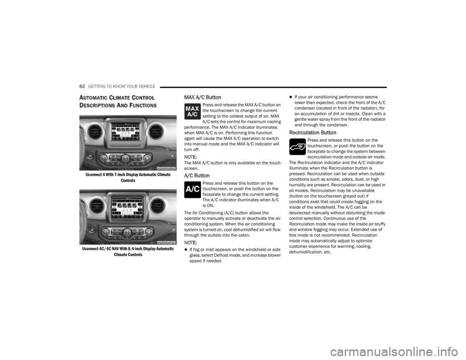
AUTOMATIC CLIMATE CONTROL
D
ESCRIPTIONS AND FUNCTIONS
Uconnect 4 With 7-inch Display Automatic Climate
Controls
Uconnect 4C/4C NAV With 8.4-inch Display Automatic Climate Controls
MAX A/C Button
Press and release the MAX A/C button on
the touchscreen to change the current
setting to the coldest output of air. MAX
A/C sets the control for maximum cooling
performance. The MAX A/C indicator illuminates
when MAX A/C is on. Performing this function
again will cause the MAX A/C operation to switch
into manual mode and the MAX A/C indicator will
turn off.
NOTE:The MAX A/C button is only available on the touch -
screen.
A/C Button
Press and release this button on the
touchscreen, or push the button on the
faceplate to change the current setting.
The A/C indicator illuminates when A/C
is ON.
The Air Conditioning (A/C) button allows the
operator to manually activate or deactivate the air
conditioning system. When the air conditioning
system is turned on, cool dehumidified air will flow
through the outlets into the cabin.
NOTE:
If fog or mist appears on the windshield or side
glass, select Defrost mode, and increase blower
speed if needed.
If your air conditioning performance seems
lower than expected, check the front of the A/C
condenser (located in front of the radiator), for
an accumulation of dirt or insects. Clean with a
gentle water spray from the front of the radiator
and through the condenser.
Recirculation Button
Press and release this button on the
touchscreen, or push the button on the
faceplate to change the system between
recirculation mode and outside air mode.
The Recirculation indicator and the A/C indicator
illuminate when the Recirculation button is
pressed. Recirculation can be used when outside
conditions such as smoke, odors, dust, or high
humidity are present. Recirculation can be used in
all modes. Recirculation may be unavailable
(button on the touchscreen grayed out) if
conditions exist that could create fogging on the
inside of the windshield. The A/C can be
deselected manually without disturbing the mode
control selection. Continuous use of the
Recirculation mode may make the inside air stuffy
and window fogging may occur. Extended use of
this mode is not recommended. Recirculation
mode may automatically adjust to optimize
customer experience for warming, cooling,
dehumidification, etc.
23_JT_OM_EN_USC_t.book Page 62
Page 65 of 448
GETTING TO KNOW YOUR VEHICLE63
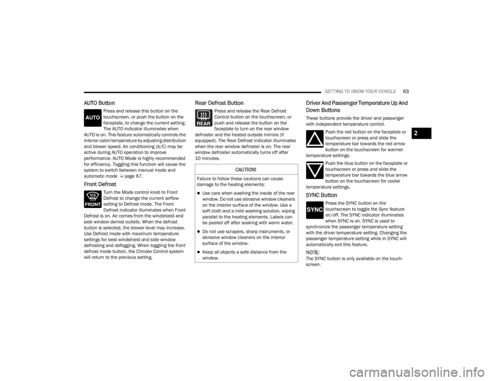
AUTO Button
Press and release this button on the
touchscreen, or push the button on the
faceplate, to change the current setting.
The AUTO indicator illuminates when
AUTO is on. This feature automatically controls the
interior cabin temperature by adjusting distribution
and blower speed. Air conditioning (A/C) may be
active during AUTO operation to improve
performance. AUTO Mode is highly recommended
for efficiency. Toggling this function will cause the
system to switch between manual mode and
automatic mode Ú page 67.
Front Defrost
Turn the Mode control knob to Front
Defrost to change the current airflow
setting to Defrost mode. The Front
Defrost indicator illuminates when Front
Defrost is on. Air comes from the windshield and
side window demist outlets. When the defrost
button is selected, the blower level may increase.
Use Defrost mode with maximum temperature
settings for best windshield and side window
defrosting and defogging. When toggling the front
defrost mode button, the Climate Control system
will return to the previous setting.
Rear Defrost Button
Press and release the Rear Defrost
Control button on the touchscreen, or
push and release the button on the
faceplate to turn on the rear window
defroster and the heated outside mirrors (if
equipped). The Rear Defrost indicator illuminates
when the rear window defroster is on. The rear
window defroster automatically turns off after
10 minutes.
Driver And Passenger Temperature Up And
Down Buttons
These buttons provide the driver and passenger
with independent temperature control.
Push the red button on the faceplate or
touchscreen or press and slide the
temperature bar towards the red arrow
button on the touchscreen for warmer
temperature settings.
Push the blue button on the faceplate or
touchscreen or press and slide the
temperature bar towards the blue arrow
button on the touchscreen for cooler
temperature settings.
SYNC Button
Press the SYNC button on the
touchscreen to toggle the Sync feature
on/off. The SYNC indicator illuminates
when SYNC is on. SYNC is used to
synchronize the passenger temperature setting
with the driver temperature setting. Changing the
passenger temperature setting while in SYNC will
automatically exit this feature.
NOTE:The SYNC button is only available on the touch-
screen.
CAUTION!
Failure to follow these cautions can cause
damage to the heating elements:
Use care when washing the inside of the rear
window. Do not use abrasive window cleaners
on the interior surface of the window. Use a
soft cloth and a mild washing solution, wiping
parallel to the heating elements. Labels can
be peeled off after soaking with warm water.
Do not use scrapers, sharp instruments, or
abrasive window cleaners on the interior
surface of the window.
Keep all objects a safe distance from the
window.
2
23_JT_OM_EN_USC_t.book Page 63
Page 66 of 448
64GETTING TO KNOW YOUR VEHICLE
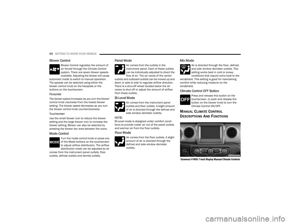
Blower Control
Blower Control regulates the amount of
air forced through the Climate Control
system. There are seven blower speeds
available. Adjusting the blower will cause
automatic mode to switch to manual operation.
The speeds can be selected using either the
blower control knob on the faceplate or the
buttons on the touchscreen.
Faceplate
The blower speed increases as you turn the blower
control knob clockwise from the lowest blower
setting. The blower speed decreases as you turn
the blower control knob counterclockwise.
Touchscreen
Use the small blower icon to reduce the blower
setting and the large blower icon to increase the
blower setting. Blower can also be selected by
pressing the blower bar area between the icons.
Mode Control
Turn the mode control knob or press one
of the Mode buttons on the touchscreen
to adjust airflow distribution. The airflow
distribution mode can be adjusted so air
comes from the instrument panel outlets, floor
outlets, defrost outlets and demist outlets.
Panel Mode
Air comes from the outlets in the
instrument panel. Each of these outlets
can be individually adjusted to direct the
flow of air. The air vanes of the center
outlets and outboard outlets can be moved up and
down or side to side to regulate airflow direction.
There is a shut-off wheel located below the air
vanes to shut off or adjust the amount of airflow
from these outlets.
Bi-Level Mode
Air comes from the instrument panel
outlets and floor outlets. A slight amount
of air is directed through the defrost and
side window demister outlets.
NOTE:Bi-Level mode is designed under comfort condi -
tions to provide cooler air out of the panel outlets
and warmer air from the floor outlets.
Floor Mode
Air comes from the floor outlets. A slight
amount of air is directed through the
defrost and side window demister
outlets.
Mix Mode
Air is directed through the floor, defrost,
and side window demister outlets. This
setting works best in cold or snowy
conditions that require extra heat to the
windshield. This setting is good for maintaining
comfort while reducing moisture on the
windshield.
Climate Control OFF Button
Press and release this button on the
touchscreen, or push and release the
button on the blower knob to turn the
Climate Control ON/OFF.
MANUAL CLIMATE CONTROL
D
ESCRIPTIONS AND FUNCTIONS
Uconnect 4 With 7-inch Display Manual Climate Controls
23_JT_OM_EN_USC_t.book Page 64