height JEEP GLADIATOR 2023 Owners Manual
[x] Cancel search | Manufacturer: JEEP, Model Year: 2023, Model line: GLADIATOR, Model: JEEP GLADIATOR 2023Pages: 448, PDF Size: 17.37 MB
Page 46 of 448
44GETTING TO KNOW YOUR VEHICLE
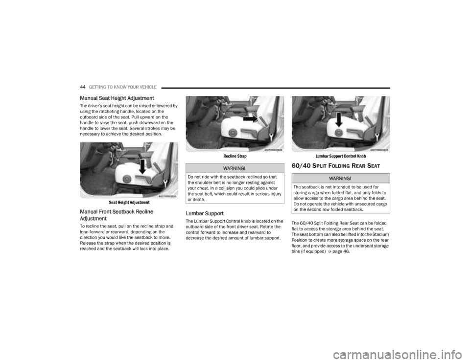
Manual Seat Height Adjustment
The driver's seat height can be raised or lowered by
using the ratcheting handle, located on the
outboard side of the seat. Pull upward on the
handle to raise the seat, push downward on the
handle to lower the seat. Several strokes may be
necessary to achieve the desired position.
Seat Height Adjustment
Manual Front Seatback Recline
Adjustment
To recline the seat, pull on the recline strap and
lean forward or rearward, depending on the
direction you would like the seatback to move.
Release the strap when the desired position is
reached and the seatback will lock into place.
Recline Strap
Lumbar Support
The Lumbar Support Control knob is located on the
outboard side of the front driver seat. Rotate the
control forward to increase and rearward to
decrease the desired amount of lumbar support.
Lumbar Support Control Knob
60/40 SPLIT FOLDING REAR SEAT
The 60/40 Split Folding Rear Seat can be folded
flat to access the storage area behind the seat.
The seat bottom can also be lifted into the Stadium
Position to create more storage space on the rear
floor, and provide access to the underseat storage
bins (if equipped) Ú
page 46.
WARNING!
Do not ride with the seatback reclined so that
the shoulder belt is no longer resting against
your chest. In a collision you could slide under
the seat belt, which could result in serious injury
or death.WARNING!
The seatback is not intended to be used for
storing cargo when folded flat, and only folds to
allow access to the cargo area behind the seat.
Do not operate the vehicle with unsecured cargo
on the second row folded seatback.
23_JT_OM_EN_USC_t.book Page 44
Page 50 of 448
48GETTING TO KNOW YOUR VEHICLE
HEAD RESTRAINTS
Head restraints are designed to reduce the risk of
injury by restricting head movement in the event of
a rear impact. Head restraints should be adjusted
so that the top of the head restraint is located
above the top of your ear.
Front Head Restraints
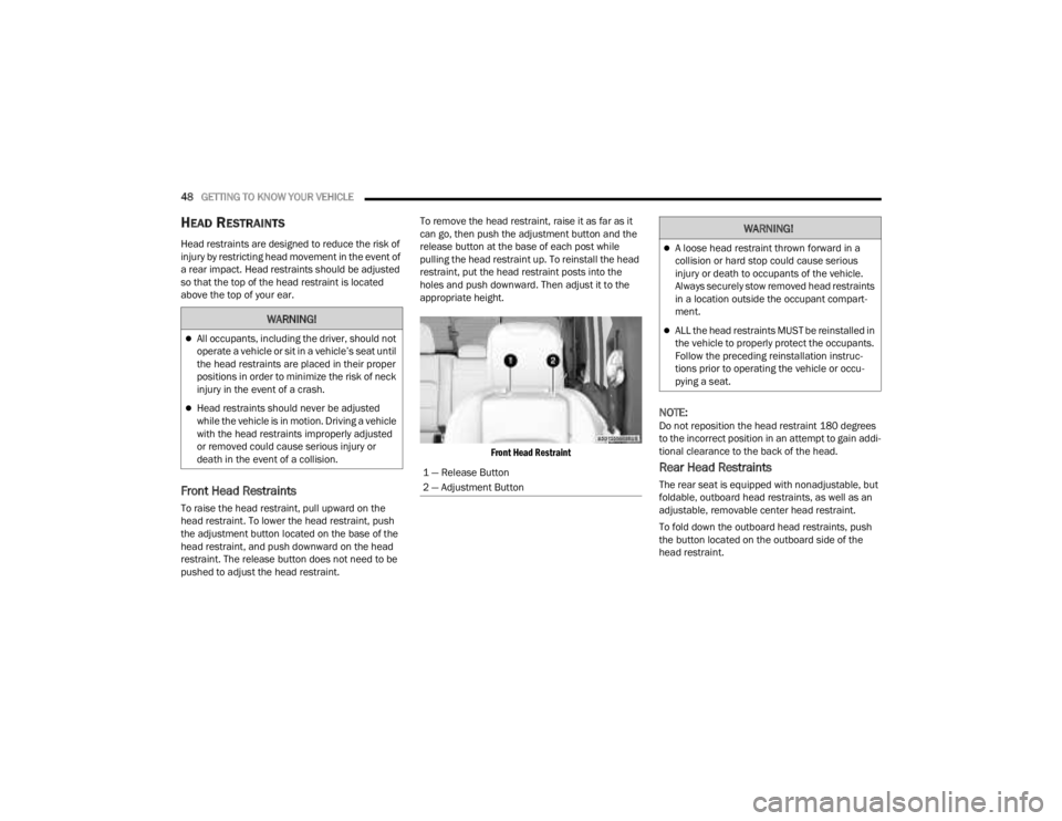
To raise the head restraint, pull upward on the
head restraint. To lower the head restraint, push
the adjustment button located on the base of the
head restraint, and push downward on the head
restraint. The release button does not need to be
pushed to adjust the head restraint. To remove the head restraint, raise it as far as it
can go, then push the adjustment button and the
release button at the base of each post while
pulling the head restraint up. To reinstall the head
restraint, put the head restraint posts into the
holes and push downward. Then adjust it to the
appropriate height.
Front Head Restraint
NOTE:Do not reposition the head restraint 180 degrees
to the incorrect position in an attempt to gain addi -
tional clearance to the back of the head.
Rear Head Restraints
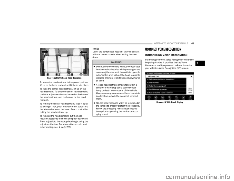
The rear seat is equipped with nonadjustable, but
foldable, outboard head restraints, as well as an
adjustable, removable center head restraint.
To fold down the outboard head restraints, push
the button located on the outboard side of the
head restraint.
WARNING!
All occupants, including the driver, should not
operate a vehicle or sit in a vehicle’s seat until
the head restraints are placed in their proper
positions in order to minimize the risk of neck
injury in the event of a crash.
Head restraints should never be adjusted
while the vehicle is in motion. Driving a vehicle
with the head restraints improperly adjusted
or removed could cause serious injury or
death in the event of a collision.
1 — Release Button
2 — Adjustment Button
WARNING!
A loose head restraint thrown forward in a
collision or hard stop could cause serious
injury or death to occupants of the vehicle.
Always securely stow removed head restraints
in a location outside the occupant compart -
ment.
ALL the head restraints MUST be reinstalled in
the vehicle to properly protect the occupants.
Follow the preceding reinstallation instruc -
tions prior to operating the vehicle or occu -
pying a seat.
23_JT_OM_EN_USC_t.book Page 48
Page 51 of 448
GETTING TO KNOW YOUR VEHICLE49
Rear Foldable Outboard Head Restraints
To return the head restraint to its upward position,
lift up on the head restraint until it locks into place.
To raise the center head restraint, lift up on the
head restraint. To lower the center head restraint,
push the adjustment button, located at the base of
the head restraint, and push down on the head
restraint.
To remove the center head restraint, raise it as far
as it can go. Then, push the adjustment button and
the release button at the base of each post while
pulling the head restraint up.
To reinstall the head restraint, put the head
restraint posts into the holes and push downward.
Then, adjust it to the appropriate height using the
adjustment button. For information on child seat
tether routing, see Ú page 299.
NOTE:Lower the center head restraint to avoid contact
with the center console when folding the seat
down.UCONNECT VOICE RECOGNITION
INTRODUCING VOICE RECOGNITION
Start using Uconnect Voice Recognition with these
helpful quick tips. It provides the key Voice
Commands and tips you need to know to control
your vehicle’s Voice Recognition (VR) system.
Uconnect 4 With 7-inch Display
WARNING!
Do not drive the vehicle without the rear seat
head restraints installed while passengers are
occupying the rear seat. In a collision, people
riding in this area without the head restraints
installed are more likely to be seriously injured
or killed.
A loose head restraint thrown forward in a
collision or hard stop could cause serious
injury or death to occupants of the vehicle.
Always securely stow removed head restraints
in a location outside the occupant compart -
ment.
ALL the head restraints MUST be reinstalled in
the vehicle to properly protect the occupants.
Follow the preceding reinstallation instruc -
tions prior to operating the vehicle or occu -
pying a seat.
2
23_JT_OM_EN_USC_t.book Page 49
Page 169 of 448
STARTING AND OPERATING167
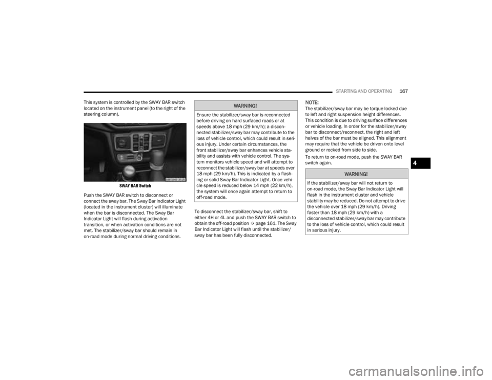
This system is controlled by the SWAY BAR switch
located on the instrument panel (to the right of the
steering column).
SWAY BAR Switch
Push the SWAY BAR switch to disconnect or
connect the sway bar. The Sway Bar Indicator Light
(located in the instrument cluster) will illuminate
when the bar is disconnected. The Sway Bar
Indicator Light will flash during activation
transition, or when activation conditions are not
met. The stabilizer/sway bar should remain in
on-road mode during normal driving conditions. To disconnect the stabilizer/sway bar, shift to
either 4H or 4L and push the SWAY BAR switch to
obtain the off-road position
Úpage 161. The Sway
Bar Indicator Light will flash until the stabilizer/
sway bar has been fully disconnected.
NOTE:The stabilizer/sway bar may be torque locked due
to left and right suspension height differences.
This condition is due to driving surface differences
or vehicle loading. In order for the stabilizer/sway
bar to disconnect/reconnect, the right and left
halves of the bar must be aligned. This alignment
may require that the vehicle be driven onto level
ground or rocked from side to side.
To return to on-road mode, push the SWAY BAR
switch again.WARNING!
Ensure the stabilizer/sway bar is reconnected
before driving on hard surfaced roads or at
speeds above 18 mph (29 km/h); a discon -
nected stabilizer/sway bar may contribute to the
loss of vehicle control, which could result in seri -
ous injury. Under certain circumstances, the
front stabilizer/sway bar enhances vehicle sta -
bility and assists with vehicle control. The sys-
tem monitors vehicle speed and will attempt to
reconnect the stabilizer/sway bar at speeds over
18 mph (29 km/h). This is indicated by a flash -
ing or solid Sway Bar Indicator Light. Once vehi -
cle speed is reduced below 14 mph (22 km/h),
the system will once again attempt to return to
off-road mode.
WARNING!
If the stabilizer/sway bar will not return to
on-road mode, the Sway Bar Indicator Light will
flash in the instrument cluster and vehicle
stability may be reduced. Do not attempt to drive
the vehicle over 18 mph (29 km/h). Driving
faster than 18 mph (29 km/h) with a
disconnected stabilizer/sway bar may contribute
to the loss of vehicle control, which could result
in serious injury.
4
23_JT_OM_EN_USC_t.book Page 167
Page 199 of 448
STARTING AND OPERATING197
TRAILER TOWING
In this section you will find safety tips and
information on limits to the type of towing you can
reasonably do with your vehicle. Before towing a
trailer, carefully review this information to tow your
load as efficiently and safely as possible.
To maintain the New Vehicle Limited Warranty
coverage, follow the requirements and
recommendations in this manual concerning
vehicles used for trailer towing.
COMMON TOWING DEFINITIONS
The following trailer towing related definitions will
assist you in understanding the following
information:
Gross Vehicle Weight Rating (GVWR)
The GVWR is the total allowable weight of your
vehicle. This includes driver, passengers, cargo
and tongue weight. The total load must be limited
so that you do not exceed the GVWR Ú page 195.
Gross Trailer Weight (GTW)
The GTW is the weight of the trailer plus the weight
of all cargo, consumables and equipment
(permanent or temporary) loaded in or on the trailer
in its "loaded and ready for operation" condition.
The recommended way to measure GTW is to put
your fully loaded trailer on a vehicle scale. The
entire weight of the trailer must be supported by
the scale.
Gross Combination Weight Rating (GCWR)
The GCWR is the total permissible weight of your
vehicle and trailer when weighed in combination.
Gross Axle Weight Rating (GAWR)
The GAWR is the maximum capacity of the front
and rear axles. Distribute the load over the front
and rear axles evenly. Make sure that you do not
exceed either front or rear GAWR Úpage 195.
Tongue Weight (TW)
The TW is the downward force exerted on the hitch
ball by the trailer. You must consider this as part of
the load on your vehicle.
Frontal Area
The frontal area is the maximum height multiplied
by the maximum width of the front of a trailer.
Trailer Sway Control (TSC) — If Equipped
The TSC is a telescoping link that can be installed
between the hitch receiver and the trailer tongue.
It typically provides adjustable friction associated
with the telescoping motion to dampen any
unwanted trailer swaying motions while traveling.
Weight-Carrying Hitch
A weight-carrying hitch supports the trailer tongue
weight, just as if it were luggage located at a hitch
ball or some other connecting point of the vehicle.
These kinds of hitches are commonly used to tow
small and medium sized trailers.
Weight-Distributing Hitch
A Weight-Distributing Hitch system works by
applying leverage through spring (load) bars. They
are typically used for heavier loads to distribute
trailer tongue weight to the tow vehicle's front axle
and the trailer axle(s). When used in accordance
with the manufacturer's directions, it provides for a
more level ride, offering more consistent steering
and brake control thereby enhancing towing
safety. The addition of a friction/hydraulic sway
control also dampens sway caused by traffic and
crosswinds and contributes positively to tow
vehicle and trailer stability. Trailer sway control and
WARNING!
If the gross trailer weight is 2,000 lb (907 kg) or
more, it is recommended to use a weight-
distributing hitch to ensure stable handling of
your vehicle. If you use a standard weight-
carrying hitch, you could lose control of your
vehicle and cause a collision.
WARNING!
It is important that you do not exceed the
maximum front or rear GAWR. A dangerous
driving condition can result if either rating is
exceeded.
4
23_JT_OM_EN_USC_t.book Page 197
Page 200 of 448
198STARTING AND OPERATING
a Weight-Distributing (load equalizing) Hitch are
recommended for heavier Tongue Weights (TW)
and may be required depending on vehicle and
trailer configuration/loading to comply with Gross
Axle Weight Rating (GAWR) requirements.
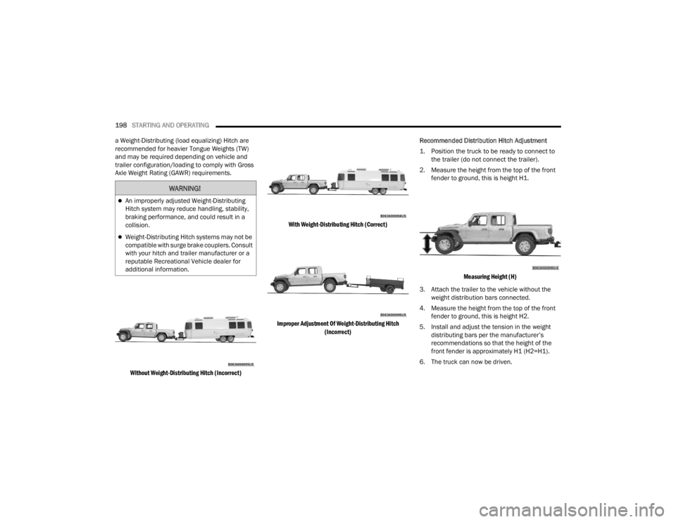
Without Weight-Distributing Hitch (Incorrect) With Weight-Distributing Hitch (Correct)
Improper Adjustment Of Weight-Distributing Hitch (Incorrect)
Recommended Distribution Hitch Adjustment
1. Position the truck to be ready to connect to
the trailer (do not connect the trailer).
2. Measure the height from the top of the front fender to ground, this is height H1.
Measuring Height (H)
3. Attach the trailer to the vehicle without the weight distribution bars connected.
4. Measure the height from the top of the front fender to ground, this is height H2.
5. Install and adjust the tension in the weight distributing bars per the manufacturer’s
recommendations so that the height of the
front fender is approximately H1 (H2=H1).
6. The truck can now be driven.
WARNING!
An improperly adjusted Weight-Distributing
Hitch system may reduce handling, stability,
braking performance, and could result in a
collision.
Weight-Distributing Hitch systems may not be
compatible with surge brake couplers. Consult
with your hitch and trailer manufacturer or a
reputable Recreational Vehicle dealer for
additional information.
23_JT_OM_EN_USC_t.book Page 198
Page 227 of 448
MULTIMEDIA225
Key Off Options/Engine Off Options
When the Key Off Options/Engine Off Options button is pressed on the touchscreen, the system displays the options related to vehicle shutoff. These settings
will only activate when the ignition is set to OFF.
NOTE:Depending on the vehicle’s options, feature settings may vary.
Setting Name Description
Easy Exit Seat This setting adjusts the seats to make exiting the vehicle easier.
Doors On Engine Off Power Delay This setting will keep certain electrical features running after the engine is
turned on. When any door is opened, the electronics will deactivate. The
available settings are “0 sec”, “45 sec”, “5 min”, and “10 min”.
Doors Off Engine Off Power Delay This setting will keep certain electrical features running after the engine is
turned off. When any door is opened, the electronics will deactivate. The
available settings are “0 sec”, “45 sec”, “5 min”, and “10 min”.
Headlight Off Delay This setting will allow you to set the amount of time the headlights remain on
after the vehicle has been turned off. The “+” will increase the amount of
time. The “-” will decrease the amount of time.
Auto Entry/Exit Suspension This setting will automatically lower the vehicle ride height for easier entry and
exit of the vehicle.
5
23_JT_OM_EN_USC_t.book Page 225
Page 279 of 448
MULTIMEDIA277
REGULATORY AND SAFETY
I
NFORMATION
US/CANADA
Exposure to Radio Frequency Radiation
The radiated output power of the internal wireless
radio is far below the FCC and IC radio frequency
exposure limits. Nevertheless, the wireless radio
will be used in such a manner that the radio is
8 inches (20 cm) or further from the human body.
The internal wireless radio operates within
guidelines found in radio frequency safety
standards and recommendations, which reflect
the consensus of the scientific community.
The radio manufacturer believes the internal
wireless radio is safe for use by consumers. The
level of energy emitted is far less than the
electromagnetic energy emitted by wireless
devices such as mobile phones. However, the use
of wireless radios may be restricted in some
situations or environments, such as aboard
airplanes. If you are unsure of restrictions, you are
encouraged to ask for authorization before turning
on the wireless radio Ú page 432.
OFF-ROAD PAGES — IF EQUIPPED
If your vehicle is equipped with Off-Road Pages, it
will provide you vehicle status while operating on
off-road conditions. It supplies information relating
to the vehicle ride height, the status of the transfer
case, the pitch and roll of the vehicle.
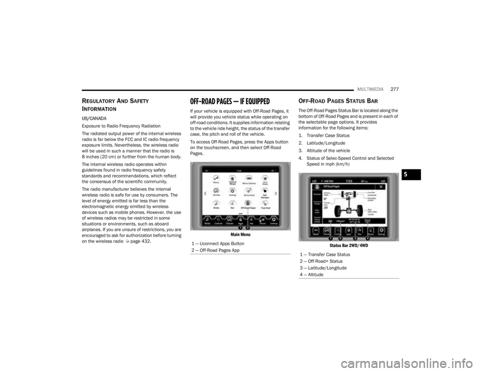
To access Off-Road Pages, press the Apps button
on the touchscreen, and then select Off-Road
Pages.
Main Menu
OFF-ROAD PAGES STATUS BAR
The Off-Road Pages Status Bar is located along the
bottom of Off-Road Pages and is present in each of
the selectable page options. It provides
information for the following items:
1. Transfer Case Status
2. Latitude/Longitude
3. Altitude of the vehicle
4. Status of Selec-Speed Control and Selected Speed in mph (km/h)
Status Bar 2WD/4WD
1 — Uconnect Apps Button
2 — Off-Road Pages App
1 — Transfer Case Status
2 — Off-Road+ Status
3 — Latitude/Longitude
4 — Altitude
5
23_JT_OM_EN_USC_t.book Page 277
Page 305 of 448
SAFETY303
5. Position the shoulder belt across the shoulder and chest with minimal, if any slack so that it
is comfortable and not resting on your neck.
The retractor will withdraw any slack in the
shoulder belt.
6. To release the seat belt, push the red button on the buckle. The seat belt will automatically
retract to its stowed position. If necessary,
slide the latch plate down the webbing to allow
the seat belt to retract fully.
Lap/Shoulder Belt Untwisting Procedure
Use the following procedure to untwist a twisted
lap/shoulder belt.
1. Position the latch plate as close as possible to the anchor point.
2. At about 6 to 12 inches (15 to 30 cm) above the latch plate, grab and twist the seat belt
webbing 180 degrees to create a fold that
begins immediately above the latch plate.
3. Slide the latch plate upward over the folded webbing. The folded webbing must enter the
slot at the top of the latch plate.
4. Continue to slide the latch plate up until it clears the folded webbing and the seat belt is
no longer twisted.
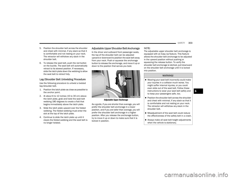
Adjustable Upper Shoulder Belt Anchorage
In the driver and outboard front passenger seats,
the top of the shoulder belt can be adjusted
upward or downward to position the seat belt away
from your neck. Push or squeeze the anchorage
button to release the anchorage, and move it up or
down to the position that serves you best.
Adjustable Upper Anchorage
As a guide, if you are shorter than average, you will
prefer the shoulder belt anchorage in a lower
position, and if you are taller than average, you will
prefer the shoulder belt anchorage in a higher
position. After you release the anchorage button,
try to move it up or down to make sure that it is
locked in position.
NOTE:The adjustable upper shoulder belt anchorage is
equipped with an Easy Up feature. This feature
allows the shoulder belt anchorage to be adjusted
in the upward position without pushing or
squeezing the release button. To verify the
shoulder belt anchorage is latched, pull downward
on the shoulder belt anchorage until it is locked
into position.
WARNING!
Wearing your seat belt incorrectly could make
your injuries in a collision much worse. You
might suffer internal injuries, or you could
even slide out of the seat belt. Follow these
instructions to wear your seat belt safely and
to keep your passengers safe, too.
Position the shoulder belt across the shoulder
and chest with minimal, if any slack so that it
is comfortable and not resting on your neck.
The retractor will withdraw any slack in the
shoulder belt.
Misadjustment of the seat belt could reduce
the effectiveness of the safety belt in a crash.
Always make all seat belt height adjustments
when the vehicle is stationary.
6
23_JT_OM_EN_USC_t.book Page 303
Page 321 of 448
SAFETY319
There are different sizes and types of restraints for children from newborn size to the child almost large enough for an adult safety belt. Always check the child
seat Owner’s Manual to make sure you have the correct seat for your child. Carefully read and follow all the instructions and warnings in the child restraint
Owner’s Manual and on all the labels attached to the child restraint.
Before buying any restraint system, make sure that it has a label certifying that it meets all applicable Safety Standards. You should also make sure that you can
install it in the vehicle where you will use it.
NOTE:
For additional information, refer to http://www.nhtsa.gov/parents-and-caregivers or call: 1–888–327–4236
Canadian residents should refer to Transport Canada’s website for additional information: https://www.tc.gc.ca/en/services/road/child-car-seat-safety.html
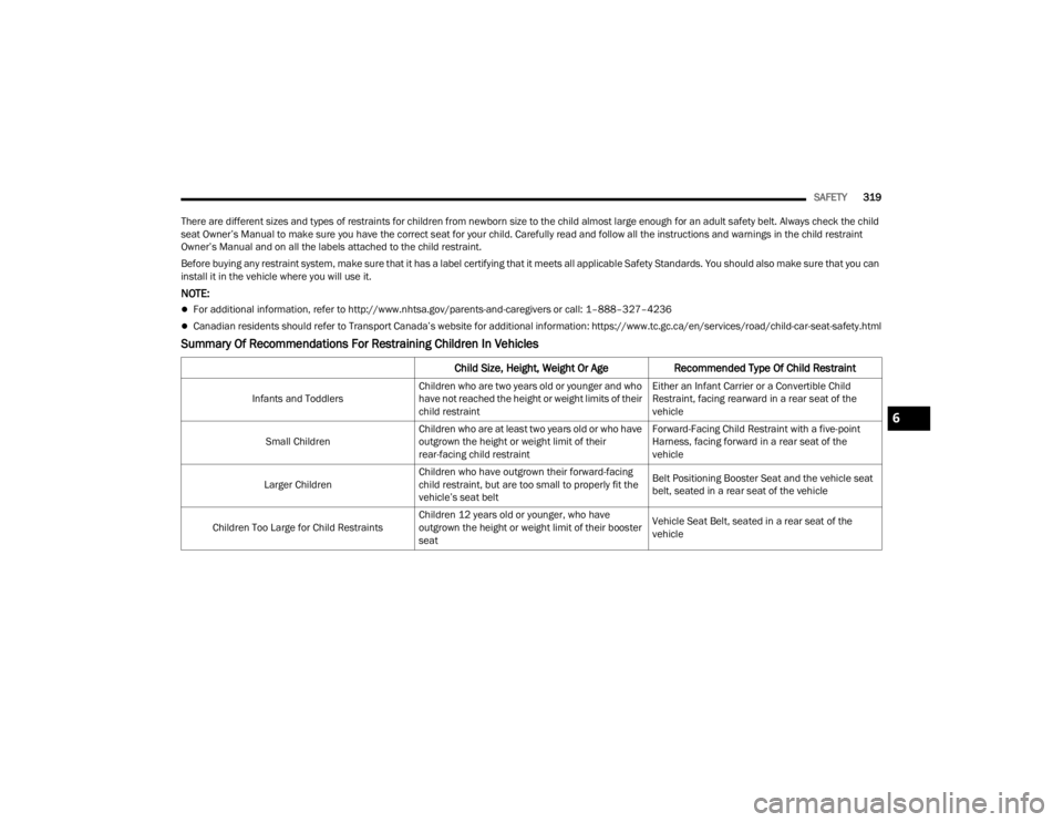
Summary Of Recommendations For Restraining Children In Vehicles
Child Size, Height, Weight Or Age Recommended Type Of Child Restraint
Infants and ToddlersChildren who are two years old or younger and who
have not reached the height or weight limits of their
child restraint Either an Infant Carrier or a Convertible Child
Restraint, facing rearward in a rear seat of the
vehicle
Small Children Children who are at least two years old or who have
outgrown the height or weight limit of their
rear-facing child restraint Forward-Facing Child Restraint with a five-point
Harness, facing forward in a rear seat of the
vehicle
Larger Children Children who have outgrown their forward-facing
child restraint, but are too small to properly fit the
vehicle’s seat belt Belt Positioning Booster Seat and the vehicle seat
belt, seated in a rear seat of the vehicle
Children Too Large for Child Restraints Children 12 years old or younger, who have
outgrown the height or weight limit of their booster
seat Vehicle Seat Belt, seated in a rear seat of the
vehicle
6
23_JT_OM_EN_USC_t.book Page 319