sensor JEEP GLADIATOR 2023 Owners Manual
[x] Cancel search | Manufacturer: JEEP, Model Year: 2023, Model line: GLADIATOR, Model: JEEP GLADIATOR 2023Pages: 448, PDF Size: 17.37 MB
Page 7 of 448

5
STOP/START SYSTEM — AUTOMATIC
TRANSMISSION (IF EQUIPPED) ........................ 169 Autostop Mode .............................................. 169Possible Reasons The Engine Does Not
Autostop ......................................................... 170
To Start The Engine While In Autostop
Mode .............................................................. 170
To Manually Turn Off The Stop/Start
System ........................................................... 171To Manually Turn On The Stop/Start
System ........................................................... 171System Malfunction ...................................... 171
STOP/START SYSTEM — MANUAL
TRANSMISSION (IF EQUIPPED) .........................171
Autostop Mode .............................................. 172Possible Reasons The Engine Does Not
Autostop ......................................................... 172
To Start The Engine While In Autostop
Mode .............................................................. 172
To Manually Turn Off The Stop/Start
System ........................................................... 173To Manually Turn On The Stop/Start
System ........................................................... 173System Malfunction ...................................... 173
CRUISE CONTROL SYSTEMS —
IF EQUIPPED ........................................................ 173
Cruise Control ............................................... 173
Adaptive Cruise Control (ACC) ...................... 175 PARKSENSE FRONT/REAR PARK ASSIST
SYSTEM — IF EQUIPPED .................................... 184
ParkSense Sensors ....................................... 184
ParkSense Warning Display ......................... 184
ParkSense Display ........................................ 184Enabling And Disabling ParkSense .............. 187Service The ParkSense Park Assist
System ........................................................... 187
Cleaning The ParkSense System ................. 187
ParkSense System Usage Precautions........ 188
PARKVIEW REAR BACK UP CAMERA............... 189
TRAILCAM SYSTEM — IF EQUIPPED ................ 190
REFUELING THE VEHICLE — GASOLINE
ENGINE (IF EQUIPPED) ....................................... 191 Fuel Filler Cap................................................ 191Loose Fuel Filler Cap Message ................... 192
REFUELING THE VEHICLE — DIESEL ENGINE
(IF EQUIPPED) ..................................................... 192
Avoid Using Contaminated Fuel ................... 193Bulk Fuel Storage — Diesel Fuel................... 193Diesel Exhaust Fluid ..................................... 193
VEHICLE LOADING .............................................. 195
Certification Label ......................................... 195
TRAILER TOWING ............................................... 197
Common Towing Definitions......................... 197
Trailer Hitch Classification ............................ 199
Trailer Towing Weights (Maximum Trailer
Weight Ratings) ............................................ 199
Trailer And Tongue Weight............................ 202
Towing Requirements ................................... 202Towing Tips .................................................... 204 RECREATIONAL TOWING (BEHIND
MOTORHOME) ...................................................... 205
Towing This Vehicle Behind Another
Vehicle ........................................................... 205
Recreational Towing — Four-Wheel Drive
Models ........................................................... 205
DRIVING TIPS ....................................................... 207
On-Road Driving Tips..................................... 207Off-Road Driving Tips .................................... 207
MULTIMEDIA
UCONNECT SYSTEMS ......................................... 214
CYBERSECURITY ................................................. 214
UCONNECT SETTINGS ......................................... 215 Customer Programmable Features ............. 215
UCONNECT INTRODUCTION................................ 230
System Overview .......................................... 230Drag & Drop Menu Bar ................................. 232
Safety And General Information................... 232
UCONNECT MODES ............................................. 233
Steering Wheel Audio Controls .................... 233
Radio Mode .................................................. 234Media Mode ................................................. 242
Phone Mode ................................................. 244
ANDROID AUTO™ & APPLE CARPLAY® —
IF EQUIPPED ......................................................... 254
Android Auto™
S
........................................ 254
Apple CarPlay®
S
....................................... 256
Android Auto™ And Apple CarPlay® Tips
And Tricks ...................................................... 258
23_JT_OM_EN_USC_t.book Page 5
Page 110 of 448
108GETTING TO KNOW YOUR VEHICLE
Adaptive Cruise Control (ACC)/Forward
Collision Warning (FCW) Sensor Protective
Cover — If Equipped
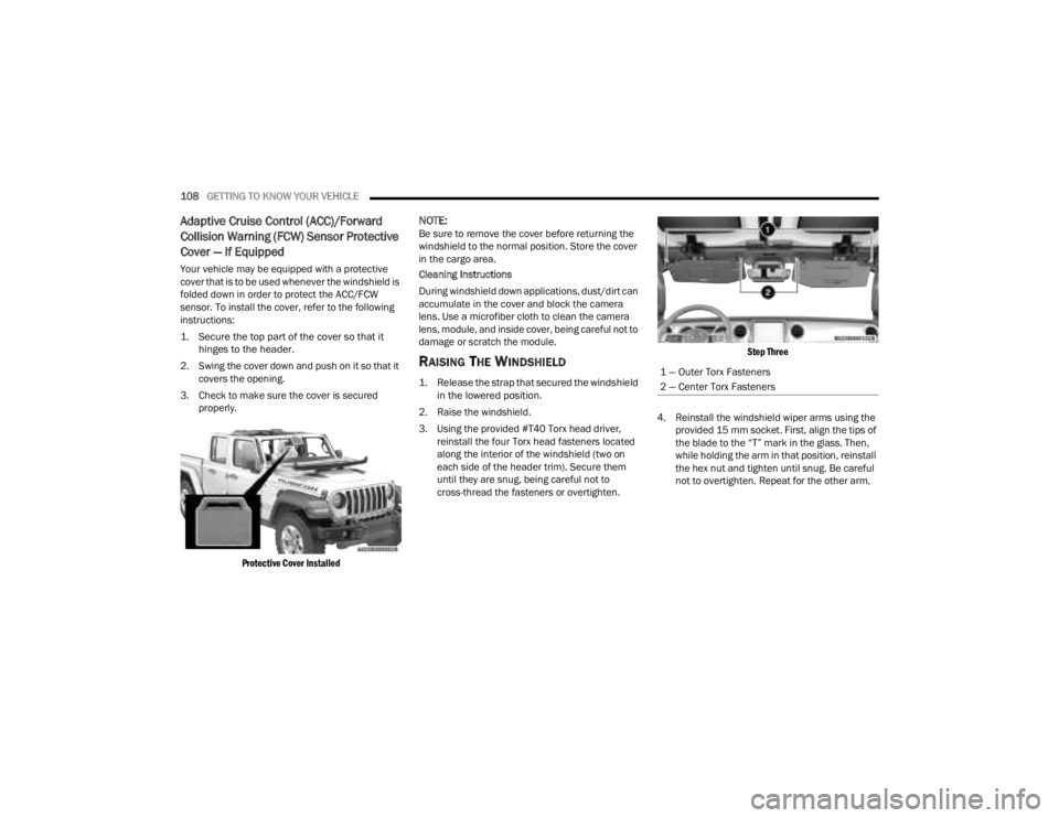
Your vehicle may be equipped with a protective
cover that is to be used whenever the windshield is
folded down in order to protect the ACC/FCW
sensor. To install the cover, refer to the following
instructions:
1. Secure the top part of the cover so that it
hinges to the header.
2. Swing the cover down and push on it so that it covers the opening.
3. Check to make sure the cover is secured properly.
Protective Cover Installed
NOTE:Be sure to remove the cover before returning the
windshield to the normal position. Store the cover
in the cargo area.
Cleaning Instructions
During windshield down applications, dust/dirt can
accumulate in the cover and block the camera
lens. Use a microfiber cloth to clean the camera
lens, module, and inside cover, being careful not to
damage or scratch the module.
RAISING THE WINDSHIELD
1. Release the strap that secured the windshield in the lowered position.
2. Raise the windshield.
3. Using the provided #T40 Torx head driver, reinstall the four Torx head fasteners located
along the interior of the windshield (two on
each side of the header trim). Secure them
until they are snug, being careful not to
cross-thread the fasteners or overtighten.
Step Three
4. Reinstall the windshield wiper arms using the provided 15 mm socket. First, align the tips of
the blade to the “T” mark in the glass. Then,
while holding the arm in that position, reinstall
the hex nut and tighten until snug. Be careful
not to overtighten. Repeat for the other arm.1 — Outer Torx Fasteners
2 — Center Torx Fasteners
23_JT_OM_EN_USC_t.book Page 108
Page 129 of 448

GETTING TO KNOW YOUR INSTRUMENT PANEL127
BATTERY SAVER ON, BATTERY SAVER
M
ODE MESSAGE, AND ELECTRICAL
L
OAD REDUCTION ACTIONS
(I
F EQUIPPED)
This vehicle is equipped with an Intelligent Battery
Sensor (IBS) to perform additional monitoring of
the electrical system and status of the vehicle
battery.
In cases when the IBS detects charging system
failure, or the vehicle battery conditions are
deteriorating, electrical load reduction actions will
take place to extend the driving time and distance
of the vehicle. This is done by reducing power to or
turning off non-essential electrical loads.
Load reduction is only active when the engine is
running. It will display a message if there is a risk
of battery depletion to the point where the vehicle
may stall due to lack of electrical supply, or will not
restart after the current drive cycle.
When load reduction is activated, the message
“Battery Saver On Some Systems May Have
Reduced Power” will appear in the instrument
cluster. These messages indicate the vehicle battery has a
low state of charge and continues to lose electrical
charge at a rate that the charging system cannot
sustain.
NOTE:
The charging system is independent from load
reduction. The charging system performs a diag
-
nostic on the charging system continuously.
If the Battery Charge Warning Light is on it may
indicate a problem with the charging system
Ú page 133.
The electrical loads that may be switched off (if
equipped), and vehicle functions which can be
affected by load reduction:
Heated Seat/Vented Seats/Heated Wheel
Rear Defroster And Heated Mirrors
HVAC System
115 Volt AC Power Inverter System
Audio and Telematics System
Loss of battery charge may indicate one or more of
the following conditions:
The charging system cannot deliver enough
electrical power to the vehicle system because
the electrical loads are larger than the capability
of the charging system. The charging system is
still functioning properly.
Turning on all possible vehicle electrical loads
(e.g. HVAC to max settings, exterior and interior
lights, overloaded power outlets +12 Volt,
115 Volt AC, USB ports) during certain driving
conditions (city driving, towing, frequent stop -
ping).
Installing options like additional lights, upfitter
electrical accessories, audio systems, alarms
and similar devices.
Unusual driving cycles (short trips separated by
long parking periods).
The vehicle was parked for an extended period
of time (weeks, months).
The battery was recently replaced and was not
charged completely.
The battery was discharged by an electrical load
left on when the vehicle was parked.
The battery was used for an extended period
with the engine not running to supply radio,
lights, chargers, +12 Volt portable appliances
like vacuum cleaners, game consoles and
similar devices.
3
23_JT_OM_EN_USC_t.book Page 127
Page 140 of 448
138GETTING TO KNOW YOUR INSTRUMENT PANEL
AdBlue® (UREA) Injection System Failure
Warning Light — If Equipped
This warning light will illuminate along
with a dedicated message on the display
(if equipped) if an unknown fluid not
conforming with acceptable
characteristics is inserted, or if an average
consumption of AdBlue® (UREA) over 50% is
detected. Contact an authorized dealer as soon as
possible. If the problem is not solved, a specific message will
appear on the Instrument Cluster Display
whenever a certain threshold is reached until it will
no longer be possible to start the engine.
When about 125 miles (200 km) are remaining
before the AdBlue® (UREA) tank is empty, a
continuous dedicated message will appear on the
instrument panel, accompanied by a buzzer sound
(if equipped).
YELLOW INDICATOR LIGHTS
4WD Indicator Light — If Equipped
This light alerts the driver that the vehicle
is in the four-wheel drive mode, and the
front and rear driveshafts are
mechanically locked together forcing the
front and rear wheels to rotate at the same speed.
4WD Low Indicator Light — If Equipped
This light alerts the driver that the vehicle
is in the 4WD Low mode. The front and
rear driveshafts are mechanically locked
together forcing the front and rear
wheels to rotate at the same speed. Low range
provides a greater gear reduction ratio to provide
increased torque at the wheels.
4WD Part Time Indicator Light —
If Equipped
This light alerts the driver that the vehicle
is in the four-wheel drive part time mode,
and the front and rear driveshafts are
mechanically locked together forcing the
front and rear wheels to rotate at the same speed.
Axle Locker Fault Indicator Light —
If Equipped
This light indicates when front and/or
rear axle locker fault has been detected.
Rear Axle Lock Indicator Light —
If Equipped
This light indicates when the rear axle
lock has been activated Ú page 161.
Front And Rear Axle Lock Indicator Light —
If Equipped
This light indicates when the front, rear,
or both axles have been locked. The
telltale will display the lock icon on the
front and rear axles to indicate the
current lock status.
CAUTION!
The TPMS has been optimized for the original
equipment tires and wheels. TPMS pressures
and warning have been established for the tire
size equipped on your vehicle. Undesirable
system operation or sensor damage may result
when using replacement equipment that is not
of the same size, type, and/or style. Aftermarket
wheels can cause sensor damage. Using
aftermarket tire sealants may cause the Tire
Pressure Monitoring System (TPMS) sensor to
become inoperable. After using an aftermarket
tire sealant it is recommended that you take
your vehicle to an authorized dealer to have your
sensor function checked.
23_JT_OM_EN_USC_t.book Page 138
Page 147 of 448
STARTING AND OPERATING145
however the ignition will remain in the ACC
position (NOT the OFF position). Never leave a
vehicle out of the PARK position, or it could roll.
3. If the gear selector is in NEUTRAL, and the vehicle speed is below 5 mph (8 km/h),
pushing the ENGINE START/STOP button once
will turn the engine off. The ignition will remain
in the ACC position.
4. If the vehicle speed is above 5 mph (8 km/h), the ENGINE START/STOP button must be held
for two seconds (or three short pushes in a
row) to turn the engine off. The ignition will
remain in the ACC position (NOT the OFF
position) if the engine is turned off when the
transmission is not in PARK.
NOTE:The system will automatically time out and the
ignition will cycle to the OFF position after
30 minutes of inactivity if the ignition is left in the
ACC or RUN (engine not running) position and the
transmission is in PARK.
ENGINE START/STOP Button Functions — With
Driver’s Foot Off The Brake Pedal (In PARK Or
NEUTRAL Position)
The ENGINE START/STOP button operates similar
to an ignition switch. It has three modes: OFF, ACC,
and RUN. To change the ignition modes without
starting the vehicle and use the accessories, follow
these steps:
1. Starting with the ignition in the OFF position.
2. Push the ENGINE START/STOP button once to
place the ignition to the ACC position
(instrument cluster will display “ACC”).
3. Push the ENGINE START/STOP button a second time to place the ignition to the RUN
position (instrument cluster will display “ON/
RUN”).
4. Push the ENGINE START/STOP button a third time to return the ignition to the OFF position
(instrument cluster will display “OFF”).
AUTOPARK
AutoPark is a supplemental feature to assist in
placing the vehicle in PARK should the situations
on the following pages occur. It is a back-up system
and should not be relied upon as the primary
method by which the driver shifts the vehicle into
PARK.
The conditions under which AutoPark will engage
are outlined on the following pages. If the vehicle is not in PARK and the driver turns off
the engine, the vehicle may AutoPark.
AutoPark will engage when all of these conditions
are met:
Vehicle is equipped with an 8-speed transmis
-
sion
Driver door is ajar or if the driver door is
removed and the driver is not on the seat (seat
pad sensor detects driver missing)
WARNING!
Driver inattention could lead to failure to place
the vehicle in PARK. ALWAYS DO A VISUAL
CHECK that your vehicle is in PARK by verifying
that a solid (not blinking) “P” is indicated in
the instrument cluster display and on the gear
selector. If the "P" indicator is blinking, your
vehicle is not in PARK. As an added precau -
tion, always apply the parking brake when
exiting the vehicle.
AutoPark is a supplemental feature. It is not
designed to replace the need to shift your
vehicle into PARK. It is a back-up system and
should not be relied upon as the primary
method by which the driver shifts the vehicle
into PARK.
4
23_JT_OM_EN_USC_t.book Page 145
Page 148 of 448
146STARTING AND OPERATING
Vehicle is not in PARK
Vehicle speed is 1.2 mph (1.9 km/h) or less
Ignition is switched from ON/RUN to OFF
NOTE:For Keyless Enter ‘n Go™ equipped vehicles, the
engine will turn off and the ignition will change to
ACC position. After 30 minutes the ignition
switches to OFF automatically, unless the driver
turns the ignition OFF.
If the vehicle is not in PARK and the driver exits the
vehicle with the engine running, the vehicle may
AutoPark.
AutoPark will engage when all of these conditions
are met:
Vehicle is equipped with an 8-speed transmis -
sion
Driver door is ajar or if the driver door is
removed and the driver is not on the seat (seat
pad sensor detects driver missing)
Vehicle is not in PARK
Vehicle speed is 1.2 mph (1.9 km/h) or less
Driver seat belt is unbuckled
Brake pedal is not pressed
The message “ AutoPark Engaged Shift To P Then
Shift To Gear ” will display in the instrument cluster.
NOTE:In some cases the ParkSense graphic will be
displayed in the instrument cluster. In these cases,
the gear selector must be returned to “P” to select
desired gear.
If the driver shifts into PARK while moving, the
vehicle may AutoPark.
AutoPark will engage ONLY when vehicle speed is
1.2 mph (1.9 km/h) or less.
The message “ Vehicle Speed Is Too High To Shift
To P ” will be displayed in the instrument cluster if
vehicle speed is above 1.2 mph (1.9 km/h).
4WD LOW
AutoPark will be disabled when operating the
vehicle in 4WD LOW.
The message “ AutoPark Disabled ” will be
displayed in the instrument cluster. Additional customer warnings will be given when
both of these conditions are met:
Vehicle is not in PARK
Driver’s door is ajar
The message “ AutoPark Not Engaged” will be
displayed in the instrument cluster. A warning
chime will continue until you shift the vehicle into
PARK or the driver’s door is closed.
ALWAYS DO A VISUAL CHECK
that your vehicle is in
PARK by looking for the “P” in the instrument
cluster display and on the gear selector. As an
added precaution, always apply the parking brake
when exiting the vehicle.
EXTREME COLD WEATHER
(B
ELOW –22°F OR −30°C)
To ensure reliable starting at these temperatures,
use of an externally powered electric engine block
heater (available from an authorized dealer) is
recommended.
EXTENDED PARK STARTING
NOTE:Extended Park condition occurs when the vehicle
has not been started or driven for at least 30 days.
1. Install a battery charger or jumper cables to
the battery to ensure a full battery charge
during the crank cycle.
WARNING!
If vehicle speed is above 1.2 mph (1.9 km/h), the
transmission will default to NEUTRAL until the
vehicle speed drops below 1.2 mph (1.9 km/h). A
vehicle left in the NEUTRAL position can roll. As
an added precaution, always apply the parking
brake when exiting the vehicle.
23_JT_OM_EN_USC_t.book Page 146
Page 177 of 448
STARTING AND OPERATING175
To Accelerate For Passing
While the Cruise Control is set, press the
accelerator to pass as you would normally. When
the pedal is released, the vehicle will return to the
set speed.
USING CRUISE CONTROL ON HILLS
The transmission may downshift on hills to
maintain the vehicle set speed.
The Cruise Control system maintains speed up and
down hills. A slight speed change on moderate hills
is normal. On steep hills, a greater speed loss or
gain may occur so it may be preferable to drive
without Cruise Control.
To Resume Speed
To resume a previously set speed, push the RES
button and release. Resume can be used at any
speed above 20 mph (32 km/h).
To Deactivate
A soft tap on the brake pedal, pushing the CANC
(cancel) button, or normal brake pressure while
slowing the vehicle will deactivate the Cruise
Control without erasing the set speed from
memory.
The following conditions will also deactivate the
Cruise Control without erasing the set speed from
memory:
Vehicle parking brake is applied
Stability event occurs
Gear selector is moved out of DRIVE
Engine overspeed occurs
Clutch pedal is pressed (manual transmission
only)
Vehicle is operating at a low RPM (manual trans -
mission only)
Pushing the on/off button or placing the ignition in
the OFF position, erases the set speed from
memory.
ADAPTIVE CRUISE CONTROL (ACC)
Adaptive Cruise Control (ACC) increases the driving
convenience provided by Cruise Control while
traveling on highways and major roadways.
However, it is not a safety system and not designed
to prevent collisions. The Cruise Control function
performs differently if your vehicle is not equipped
with ACC Ú page 173.
ACC will allow you to keep Cruise Control engaged
in light to moderate traffic conditions without the
constant need to reset your speed. ACC utilizes a
radar sensor and a forward-facing camera
designed to detect a vehicle directly ahead of you
to maintain a set speed.
NOTE:
If the ACC sensor detects a vehicle ahead, ACC
will apply limited braking or accelerate (not to
exceed the original set speed) automatically to
maintain a preset following distance, while
matching the speed of the vehicle ahead.
Any chassis/suspension or tire size modifica -
tions to the vehicle will affect the performance
of the Adaptive Cruise Control and Forward Colli -
sion Warning system.
Fixed Speed Cruise Control (ACC not enabled)
will not detect vehicles directly ahead of you.
Always be aware of the feature selected
Ú page 432.
WARNING!
Cruise Control can be dangerous where the
system cannot maintain a constant speed. Your
vehicle could go too fast for the conditions, and
you could lose control and have an accident. Do
not use Cruise Control in heavy traffic or on
roads that are winding, icy, snow-covered or
slippery.
4
23_JT_OM_EN_USC_t.book Page 175
Page 182 of 448
180STARTING AND OPERATING
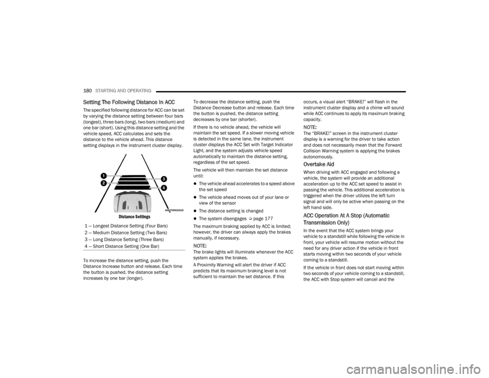
Setting The Following Distance In ACC
The specified following distance for ACC can be set
by varying the distance setting between four bars
(longest), three bars (long), two bars (medium) and
one bar (short). Using this distance setting and the
vehicle speed, ACC calculates and sets the
distance to the vehicle ahead. This distance
setting displays in the instrument cluster display.
Distance Settings
To increase the distance setting, push the
Distance Increase button and release. Each time
the button is pushed, the distance setting
increases by one bar (longer). To decrease the distance setting, push the
Distance Decrease button and release. Each time
the button is pushed, the distance setting
decreases by one bar (shorter).
If there is no vehicle ahead, the vehicle will
maintain the set speed. If a slower moving vehicle
is detected in the same lane, the instrument
cluster displays the ACC Set with Target Indicator
Light, and the system adjusts vehicle speed
automatically to maintain the distance setting,
regardless of the set speed.
The vehicle will then maintain the set distance
until:
The vehicle ahead accelerates to a speed above
the set speed
The vehicle ahead moves out of your lane or
view of the sensor
The distance setting is changed
The system disengages Ú
page 177
The maximum braking applied by ACC is limited;
however, the driver can always apply the brakes
manually, if necessary.
NOTE:The brake lights will illuminate whenever the ACC
system applies the brakes.
A Proximity Warning will alert the driver if ACC
predicts that its maximum braking level is not
sufficient to maintain the set distance. If this occurs, a visual alert “BRAKE!” will flash in the
instrument cluster display and a chime will sound
while ACC continues to apply its maximum braking
capacity.
NOTE:The “BRAKE!” screen in the instrument cluster
display is a warning for the driver to take action
and does not necessarily mean that the Forward
Collision Warning system is applying the brakes
autonomously.
Overtake Aid
When driving with ACC engaged and following a
vehicle, the system will provide an additional
acceleration up to the ACC set speed to assist in
passing the vehicle. This additional acceleration is
triggered when the driver utilizes the left turn
signal and will only be active when passing on the
left hand side.
ACC Operation At A Stop (Automatic
Transmission Only)
In the event that the ACC system brings your
vehicle to a standstill while following the vehicle in
front, your vehicle will resume motion without the
need for any driver action if the vehicle in front
starts moving within two seconds of your vehicle
coming to a standstill.
If the vehicle in front does not start moving within
two seconds of your vehicle coming to a standstill,
the ACC with Stop system will cancel and the
1 — Longest Distance Setting (Four Bars)
2 — Medium Distance Setting (Two Bars)
3 — Long Distance Setting (Three Bars)
4 — Short Distance Setting (One Bar)
23_JT_OM_EN_USC_t.book Page 180
Page 183 of 448
STARTING AND OPERATING181
brakes will release. A cancel message will display
on the instrument cluster display and produce a
warning chime. Driver intervention will be required
at this moment.
While ACC with Stop is holding your vehicle at a
standstill, if the driver seat belt is unbuckled or the
driver door is opened, the ACC with Stop system
will cancel and the brakes will release. A cancel
message will display on the instrument cluster
display and produce a warning chime. Driver
intervention will be required at this moment.
Display Warnings And Maintenance
“WIPE FRONT RADAR SENSOR IN FRONT OF
VEHICLE” WARNING
The “ACC/FCW Unavailable Wipe Front Radar
Sensor” warning will display and a chime will
sound when conditions temporarily limit system
performance. This most often occurs at times of poor visibility,
such as in snow or heavy rain. The ACC system may
also become temporarily blinded due to
obstructions, such as mud, dirt or ice. In these
cases, the instrument cluster display will display
the above message and the system will deactivate.
This message can sometimes be displayed while
driving in highly reflective areas (i.e. ice and snow,
or tunnels with reflective tiles). The ACC system will
recover after the vehicle has left these areas.
Under rare conditions, when the radar is not
tracking any vehicles or objects in its path this
warning may temporarily occur.
NOTE:If the “ACC/FCW Unavailable Wipe Front Radar
Sensor” warning is active, Fixed Speed Cruise
Control is still available.
If weather conditions are not a factor, the driver
should examine the sensor. It may require cleaning
or removal of an obstruction. The sensor is located
in the center of the vehicle behind the lower grille.
To keep the ACC system operating properly, it is
important to note the following maintenance
items:
Always keep the sensor clean. Carefully wipe the
sensor lens with a soft cloth. Be cautious not to
damage the sensor lens.
Do not remove any screws from the sensor.
Doing so could cause an ACC system malfunc
-
tion or failure and require a sensor realignment.
If the sensor or front end of the vehicle is
damaged due to a collision, see an authorized
dealer for service.
Do not attach or install any accessories near the
sensor, including transparent material or after -
market grilles. Doing so could cause an ACC
system failure or malfunction.
When the condition that deactivated the system is
no longer present, the system will return to the
“Adaptive Cruise Control Off” state and will resume
function by simply reactivating it.
NOTE:If the “ACC/FCW Unavailable Wipe Front Radar
Sensor” message occurs frequently (e.g. more
than once on every trip) without any snow, rain,
mud, or other obstruction, have the radar sensor
realigned at an authorized dealer.
WARNING!
When the ACC system is resumed, the driver
must ensure that there are no pedestrians,
vehicles or objects in the path of the vehicle.
Failure to follow these warnings can result in a
collision and death or serious personal injury.
4
23_JT_OM_EN_USC_t.book Page 181
Page 186 of 448
184STARTING AND OPERATING
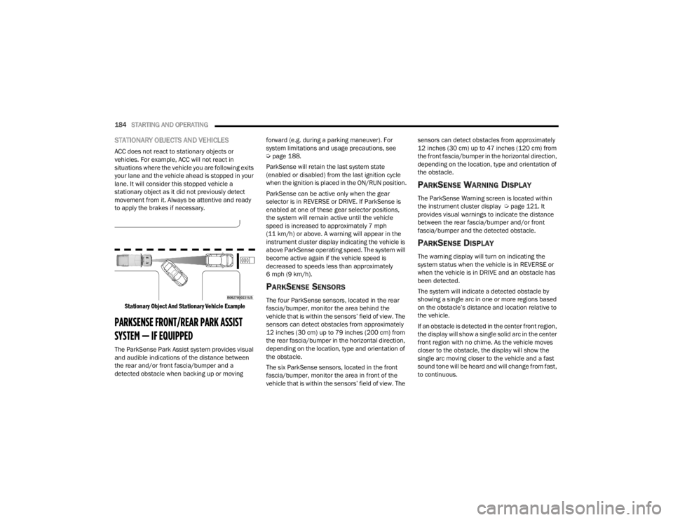
STATIONARY OBJECTS AND VEHICLES
ACC does not react to stationary objects or
vehicles. For example, ACC will not react in
situations where the vehicle you are following exits
your lane and the vehicle ahead is stopped in your
lane. It will consider this stopped vehicle a
stationary object as it did not previously detect
movement from it. Always be attentive and ready
to apply the brakes if necessary.
Stationary Object And Stationary Vehicle Example
PARKSENSE FRONT/REAR PARK ASSIST
SYSTEM — IF EQUIPPED
The ParkSense Park Assist system provides visual
and audible indications of the distance between
the rear and/or front fascia/bumper and a
detected obstacle when backing up or moving forward (e.g. during a parking maneuver). For
system limitations and usage precautions, see
Ú
page 188.
ParkSense will retain the last system state
(enabled or disabled) from the last ignition cycle
when the ignition is placed in the ON/RUN position.
ParkSense can be active only when the gear
selector is in REVERSE or DRIVE. If ParkSense is
enabled at one of these gear selector positions,
the system will remain active until the vehicle
speed is increased to approximately 7 mph
(11 km/h) or above. A warning will appear in the
instrument cluster display indicating the vehicle is
above ParkSense operating speed. The system will
become active again if the vehicle speed is
decreased to speeds less than approximately
6 mph (9 km/h).
PARKSENSE SENSORS
The four ParkSense sensors, located in the rear
fascia/bumper, monitor the area behind the
vehicle that is within the sensors’ field of view. The
sensors can detect obstacles from approximately
12 inches (30 cm) up to 79 inches (200 cm) from
the rear fascia/bumper in the horizontal direction,
depending on the location, type and orientation of
the obstacle.
The six ParkSense sensors, located in the front
fascia/bumper, monitor the area in front of the
vehicle that is within the sensors’ field of view. The sensors can detect obstacles from approximately
12 inches (30 cm) up to 47 inches (120 cm) from
the front fascia/bumper in the horizontal direction,
depending on the location, type and orientation of
the obstacle.
PARKSENSE WARNING DISPLAY
The ParkSense Warning screen is located within
the instrument cluster display Ú
page 121. It
provides visual warnings to indicate the distance
between the rear fascia/bumper and/or front
fascia/bumper and the detected obstacle.
PARKSENSE DISPLAY
The warning display will turn on indicating the
system status when the vehicle is in REVERSE or
when the vehicle is in DRIVE and an obstacle has
been detected.
The system will indicate a detected obstacle by
showing a single arc in one or more regions based
on the obstacle’s distance and location relative to
the vehicle.
If an obstacle is detected in the center front region,
the display will show a single solid arc in the center
front region with no chime. As the vehicle moves
closer to the obstacle, the display will show the
single arc moving closer to the vehicle and a fast
sound tone will be heard and will change from fast,
to continuous.
23_JT_OM_EN_USC_t.book Page 184