clutch JEEP GRAND CHEROKEE 2001 Owners Manual
[x] Cancel search | Manufacturer: JEEP, Model Year: 2001, Model line: GRAND CHEROKEE, Model: JEEP GRAND CHEROKEE 2001Pages: 993, PDF Size: 50.98 MB
Page 52 of 993

Fig. 40 Clutch Pack and Upper Side Gear
Page 582 of 993
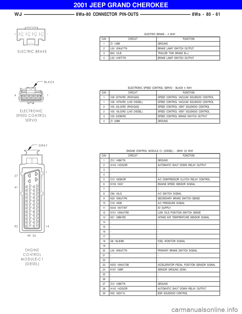
ELECTRONIC SPEED CONTROL SERVO - BLACK 4 WAY
CAV CIRCUIT FUNCTION
1 V36 20TN/RD (RHD/GAS) SPEED CONTROL VACUUM SOLENOID CONTROL
1 V36 18TN/RD (LHD DIESEL) SPEED CONTROL VACUUM SOLENOID CONTROL
2 V35 20LG/RD (RHD/GAS) SPEED CONTROL VENT SOLENOID CONTROL
2 V35 18LG/RD (LHD DIESEL) SPEED CONTROL VENT SOLENOID CONTROL
3 V30 20DB/RD SPEED CONTROL BRAKE SWITCH OUTPUT
4 Z1 20BK GROUND
ENGINE CONTROL MODULE C1 (DIESEL) - GRAY 52 WAY
CAV CIRCUIT FUNCTION
1 Z12 14BK/TN GROUND
2 A142 14DG/OR AUTOMATIC SHUT DOWN RELAY OUTPUT
3- -
4- -
5 C13 18DB/OR A/C COMPRESSOR CLUTCH RELAY CONTROL
6 K159 16GY ENGINE SPEED SENSOR SIGNAL
7- -
8 C90 18LG A/C SWITCH SIGNAL
9 K29 18WaT/PK SECONDARY BRAKE SWITCH SENSE
10 C18 18DB A/C PRESSURE SIGNAL
11 K440 18VT/WT 5V SUPPLY
12 K151 18WaT/RD LOW IDLE POSITION SWITCH SENSE
13 K21 18BK/RD INTAKE AIR TEMPERATURE SENSOR SIGNAL
14 - -
15 - -
16 - -
17 - -
18 G8 18LB/BK FUEL MONITOR SIGNAL
19 - -
20 L50 18WaT/TN PRIMARY BRAKE SWITCH SIGNAL
21 - -
22 - -
23 K255 18WaT/DB ACCELERATOR PEDAL POSITION SENSOR SIGNAL
24 K167 18BR SENSOR GROUND (ECM)
25 - -
26 - -
27 Z12 14BK/TN GROUND
28 A142 14DG/OR AUTOMATIC SHUT DOWN RELAY OUTPUT
29 K35 18GY/YL EGR SOLENOID CONTROL
WJ8Wa-80 CONNECTOR PIN-OUTS 8Wa - 80 - 61
Page 616 of 993
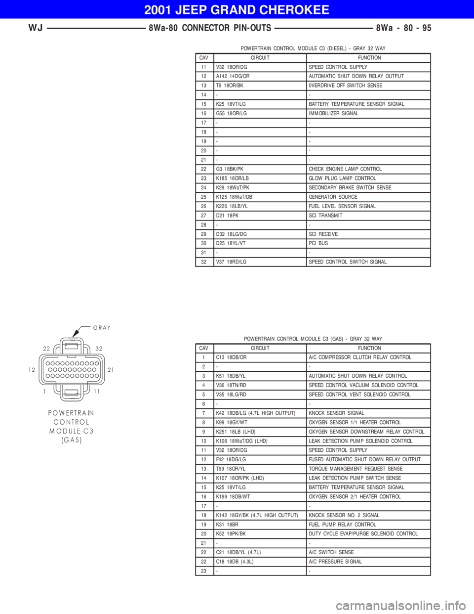
POWERTRAIN CONTROL MODULE C3 (GAS) - GRAY 32 WAY
CAV CIRCUIT FUNCTION
1 C13 18DB/OR A/C COMPRESSOR CLUTCH RELAY CONTROL
2- -
3 K51 18DB/YL AUTOMATIC SHUT DOWN RELAY CONTROL
4 V36 18TN/RD SPEED CONTROL VACUUM SOLENOID CONTROL
5 V35 18LG/RD SPEED CONTROL VENT SOLENOID CONTROL
6- -
7 K42 18DB/LG (4.7L HIGH OUTPUT) KNOCK SENSOR SIGNAL
8 K99 18GY/WT OXYGEN SENSOR 1/1 HEATER CONTROL
9 K251 18LB (LHD) OXYGEN SENSOR DOWNSTREAM RELAY CONTROL
10 K106 18WaT/DG (LHD) LEAK DETECTION PUMP SOLENOID CONTROL
11 V32 18OR/DG SPEED CONTROL SUPPLY
12 F42 18DG/LG FUSED AUTOMATIC SHUT DOWN RELAY OUTPUT
13 T99 18OR/YL TORQUE MANAGEMENT REQUEST SENSE
14 K107 18OR/PK (LHD) LEAK DETECTION PUMP SWITCH SENSE
15 K25 18VT/LG BATTERY TEMPERATURE SENSOR SIGNAL
16 K199 18DB/WT OXYGEN SENSOR 2/1 HEATER CONTROL
17 - -
18 K142 18GY/BK (4.7L HIGH OUTPUT) KNOCK SENSOR NO. 2 SIGNAL
19 K31 18BR FUEL PUMP RELAY CONTROL
20 K52 18PK/BK DUTY CYCLE EVAP/PURGE SOLENOID CONTROL
21 - -
22 C21 18DB/YL (4.7L) A/C SWITCH SENSE
22 C18 18DB (4.0L) A/C PRESSURE SIGNAL
23 - -
WJ8Wa-80 CONNECTOR PIN-OUTS 8Wa - 80 - 95
Page 631 of 993
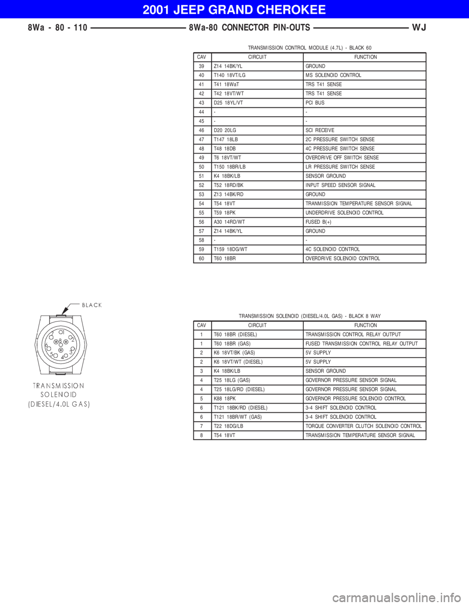
TRANSMISSION SOLENOID (DIESEL/4.0L GAS) - BLACK 8 WAY
CAV CIRCUIT FUNCTION
1 T60 18BR (DIESEL) TRANSMISSION CONTROL RELAY OUTPUT
1 T60 18BR (GAS) FUSED TRANSMISSION CONTROL RELAY OUTPUT
2 K6 18VT/BK (GAS) 5V SUPPLY
2 K6 18VT/WT (DIESEL) 5V SUPPLY
3 K4 18BK/LB SENSOR GROUND
4 T25 18LG (GAS) GOVERNOR PRESSURE SENSOR SIGNAL
4 T25 18LG/RD (DIESEL) GOVERNOR PRESSURE SENSOR SIGNAL
5 K88 18PK GOVERNOR PRESSURE SOLENOID CONTROL
6 T121 18BK/RD (DIESEL) 3-4 SHIFT SOLENOID CONTROL
6 T121 18BR/WT (GAS) 3-4 SHIFT SOLENOID CONTROL
7 T22 18DG/LB TORQUE CONVERTER CLUTCH SOLENOID CONTROL
8 T54 18VT TRANSMISSION TEMPERATURE SENSOR SIGNAL
8Wa - 80 - 110 8Wa-80 CONNECTOR PIN-OUTSWJ
Page 742 of 993
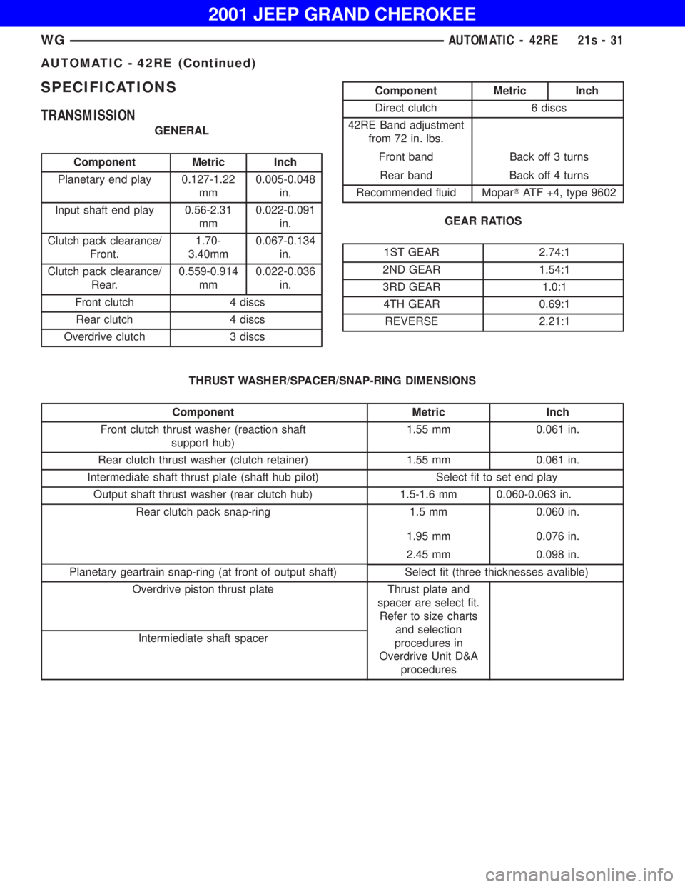
Component Metric Inch
Planetary end play 0.127-1.22
mm0.005-0.048
in.
Input shaft end play 0.56-2.31
mm0.022-0.091
in.
Clutch pack clearance/
Front.1.70-
3.40mm0.067-0.134
in.
Clutch pack clearance/
Rear.0.559-0.914
mm0.022-0.036
in.
Front clutch 4 discs
Rear clutch 4 discs
Overdrive clutch 3 discs
Component Metric Inch
Front clutch thrust washer (reaction shaft
support hub)1.55 mm 0.061 in.
Rear clutch thrust washer (clutch retainer) 1.55 mm 0.061 in.
Intermediate shaft thrust plate (shaft hub pilot) Select fit to set end play
Output shaft thrust washer (rear clutch hub) 1.5-1.6 mm 0.060-0.063 in.
Rear clutch pack snap-ring 1.5 mm 0.060 in.
1.95 mm 0.076 in.
2.45 mm 0.098 in.
Planetary geartrain snap-ring (at front of output shaft) Select fit (three thicknesses avalible)
Overdrive piston thrust plate Thrust plate and
spacer are select fit.
Refer to size charts
and selection
procedures in
Overdrive Unit D&A
procedures Intermiediate shaft spacer
WGAUTOMATIC - 42RE 21s - 31
Page 758 of 993
SHIFT
LEVER
POSITIONTRANSMISSION CLUTCHES AND BANDS OVERDRIVE CLUTCHES
FRONT
CLUTCHFRONT
BANDREAR
CLUTCHREAR
BANDOVER-
RUNNING
CLUTCHOVER-
DRIVE
CLUTCHDIRECT
CLUTCHOVER-
RUNNING
CLUTCH
Reverse X X X
Drive -
FirstXXXX
Drive -
SecondXX X X
Drive -
ThirdXX XX
Drive -
FourthXX X
Manual
SecondXXXXX
Manual
FirstXXX X X
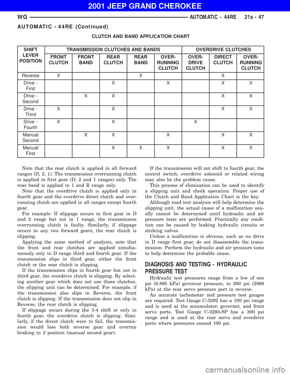
Note that the rear clutch is applied in all forward
ranges (D, 2, 1). The transmission overrunning clutch
is applied in first gear (D, 2 and 1 ranges) only. The
rear band is applied in 1 and R range only.
Note that the overdrive clutch is applied only in
fourth gear and the overdrive direct clutch and over-
running clutch are applied in all ranges except fourth
gear.
For example: If slippage occurs in first gear in D
and 2 range but not in 1 range, the transmission
overrunning clutch is faulty. Similarly, if slippage
occurs in any two forward gears, the rear clutch is
slipping.
Applying the same method of analysis, note that
the front and rear clutches are applied simulta-
neously only in D range third and fourth gear. If the
transmission slips in third gear, either the front
clutch or the rear clutch is slipping.
If the transmission slips in fourth gear but not in
third gear, the overdrive clutch is slipping. By select-
ing another gear which does not use these clutches,
the slipping unit can be determined. For example, if
the transmission also slips in Reverse, the front
clutch is slipping. If the transmission does not slip in
Reverse, the rear clutch is slipping.
If slippage occurs during the 3-4 shift or only in
fourth gear, the overdrive clutch is slipping. Simi-
larly, if the direct clutch were to fail, the transmis-
sion would lose both reverse gear and overrun
braking in 2 position (manual second gear).If the transmission will not shift to fourth gear, the
control switch, overdrive solenoid or related wiring
may also be the problem cause.
This process of elimination can be used to identify
a slipping unit and check operation. Proper use of
the Clutch and Band Application Chart is the key.
Although road test analysis will help determine the
slipping unit, the actual cause of a malfunction usu-
ally cannot be determined until hydraulic and air
pressure tests are performed. Practically any condi-
tion can be caused by leaking hydraulic circuits or
sticking valves.
Unless a malfunction is obvious, such as no drive
in D range first gear, do not disassemble the trans-
mission. Perform the hydraulic and air pressure tests
to help determine the probable cause.
DIAGNOSIS AND TESTING - HYDRAULIC
PRESSURE TEST
Hydraulic test pressures range from a low of one
psi (6.895 kPa) governor pressure, to 300 psi (2068
kPa) at the rear servo pressure port in reverse.
An accurate tachometer and pressure test gauges
are required. Test Gauge C-3292 has a 100 psi range
and is used at the accumulator, governor, and front
servo ports. Test Gauge C-3293-SP has a 300 psi
range and is used at the rear servo and overdrive
ports where pressures exceed 100 psi.
WGAUTOMATIC - 44RE 21s - 47
Page 763 of 993
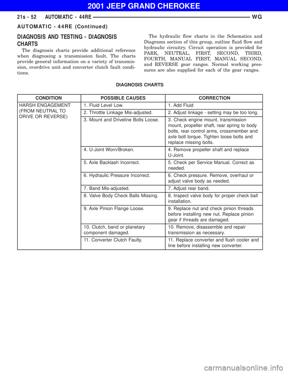
CONDITION POSSIBLE CAUSES CORRECTION
HARSH ENGAGEMENT
(FROM NEUTRAL TO
DRIVE OR REVERSE)1. Fluid Level Low. 1. Add Fluid
2. Throttle Linkage Mis-adjusted. 2. Adjust linkage - setting may be too long.
3. Mount and Driveline Bolts Loose. 3. Check engine mount, transmission
mount, propeller shaft, rear spring to body
bolts, rear control arms, crossmember and
axle bolt torque. Tighten loose bolts and
replace missing bolts.
4. U-Joint Worn/Broken. 4. Remove propeller shaft and replace
U-Joint.
5. Axle Backlash Incorrect. 5. Check per Service Manual. Correct as
needed.
6. Hydraulic Pressure Incorrect. 6. Check pressure. Remove, overhaul or
adjust valve body as needed.
7. Band Mis-adjusted. 7. Adjust rear band.
8. Valve Body Check Balls Missing. 8. Inspect valve body for proper check ball
installation.
9. Axle Pinion Flange Loose. 9. Replace nut and check pinion threads
before installing new nut. Replace pinion
gear if threads are damaged.
10. Clutch, band or planetary
component damaged.10. Remove, disassemble and repair
transmission as necessary.
11. Converter Clutch Faulty. 11. Replace converter and flush cooler and
line before installing new converter.
21s - 52 AUTOMATIC - 44REWG
AUTOMATIC - 44RE (Continued)
Page 805 of 993
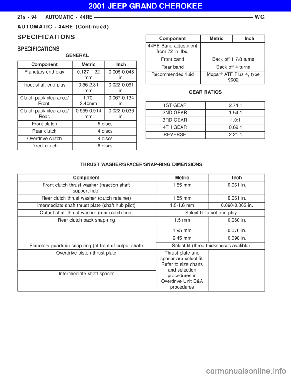
Component Metric Inch
Planetary end play 0.127-1.22
mm0.005-0.048
in.
Input shaft end play 0.56-2.31
mm0.022-0.091
in.
Clutch pack clearance/
Front.1.70-
3.40mm0.067-0.134
in.
Clutch pack clearance/
Rear.0.559-0.914
mm0.022-0.036
in.
Front clutch 5 discs
Rear clutch 4 discs
Overdrive clutch 4 discs
Direct clutch 8 discs
Component Metric Inch
Front clutch thrust washer (reaction shaft
support hub)1.55 mm 0.061 in.
Rear clutch thrust washer (clutch retainer) 1.55 mm 0.061 in.
Intermediate shaft thrust plate (shaft hub pilot) 1.5-1.6 mm 0.060-0.063 in.
Output shaft thrust washer (rear clutch hub) Select fit to set end play
Rear clutch pack snap-ring 1.5 mm 0.060 in.
1.95 mm 0.076 in.
2.45 mm 0.098 in.
Planetary geartrain snap-ring (at front of output shaft) Select fit (three thicknesses avalible)
Overdrive piston thrust plate Thrust plate and
spacer are select fit.
Refer to size charts
and selection
procedures in
Overdrive Unit D&A
procedures Intermiediate shaft spacer
21s - 94 AUTOMATIC - 44REWG
AUTOMATIC - 44RE (Continued)
Page 827 of 993
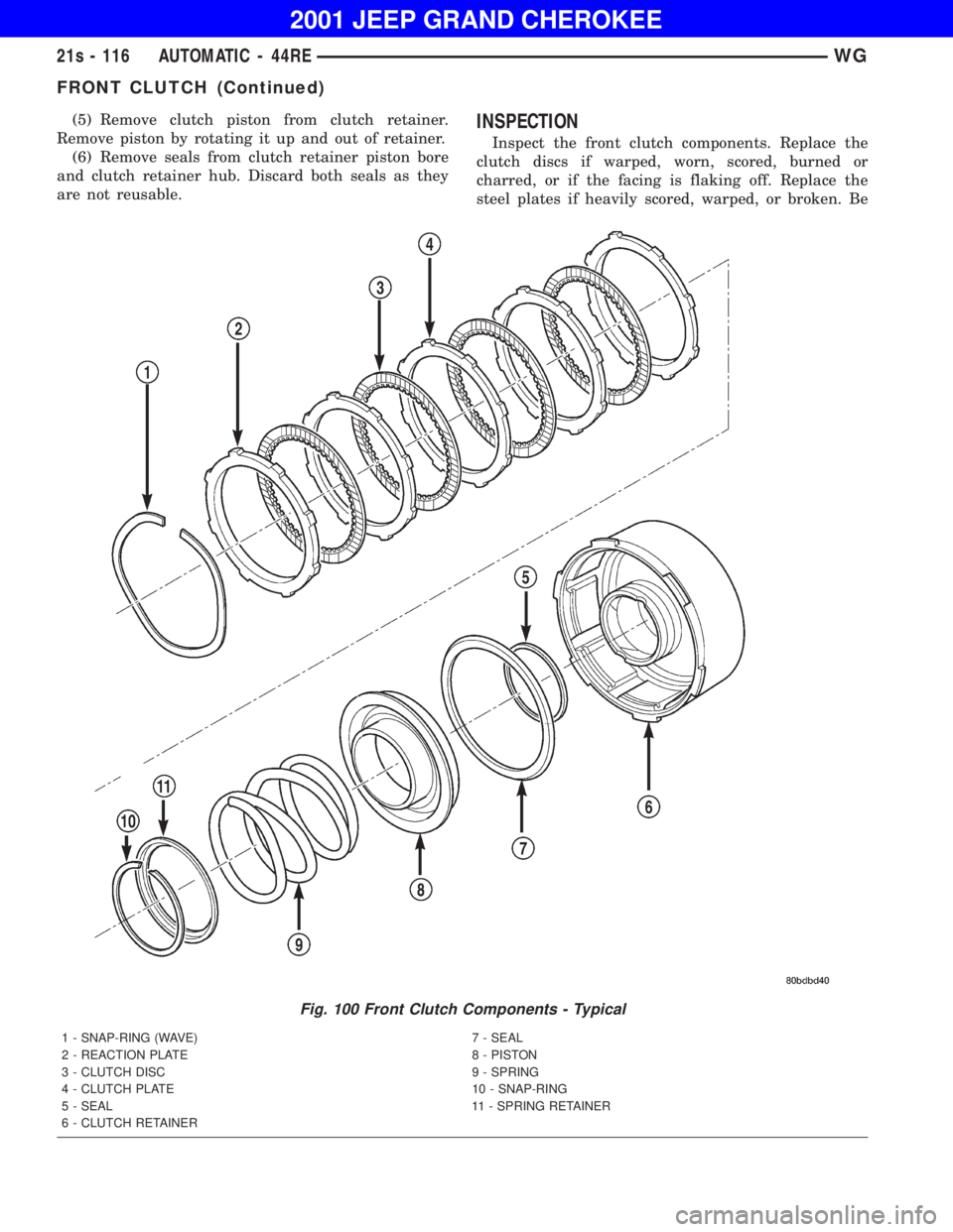
FRONT CLUTCH (Continued)
Page 829 of 993
FRONT CLUTCH (Continued)