Driver door JEEP GRAND CHEROKEE 2002 WJ / 2.G Workshop Manual
[x] Cancel search | Manufacturer: JEEP, Model Year: 2002, Model line: GRAND CHEROKEE, Model: JEEP GRAND CHEROKEE 2002 WJ / 2.GPages: 2199, PDF Size: 76.01 MB
Page 1181 of 2199
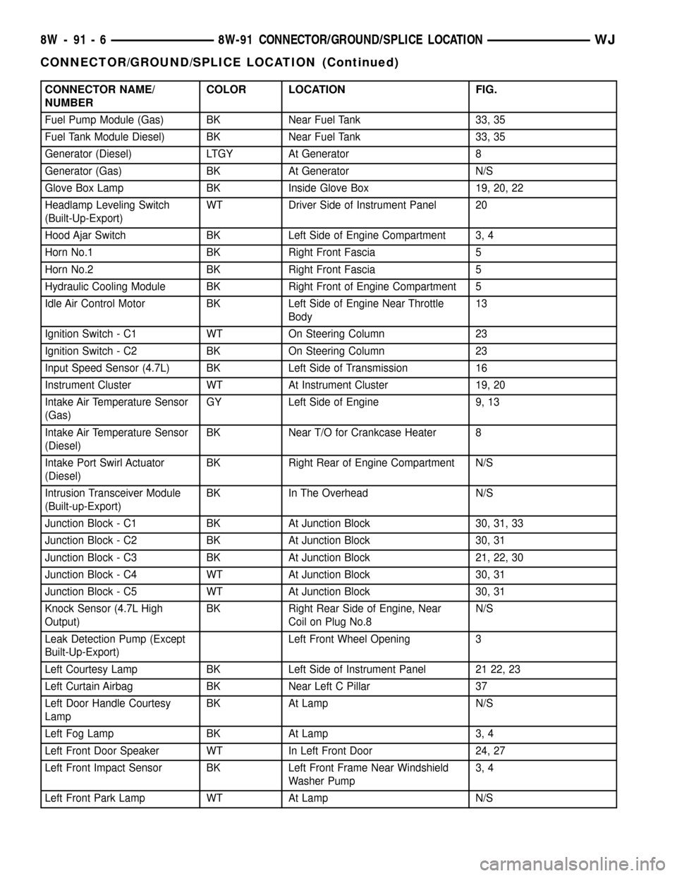
CONNECTOR NAME/
NUMBERCOLOR LOCATION FIG.
Fuel Pump Module (Gas) BK Near Fuel Tank 33, 35
Fuel Tank Module Diesel) BK Near Fuel Tank 33, 35
Generator (Diesel) LTGY At Generator 8
Generator (Gas) BK At Generator N/S
Glove Box Lamp BK Inside Glove Box 19, 20, 22
Headlamp Leveling Switch
(Built-Up-Export)WT Driver Side of Instrument Panel 20
Hood Ajar Switch BK Left Side of Engine Compartment 3, 4
Horn No.1 BK Right Front Fascia 5
Horn No.2 BK Right Front Fascia 5
Hydraulic Cooling Module BK Right Front of Engine Compartment 5
Idle Air Control Motor BK Left Side of Engine Near Throttle
Body13
Ignition Switch - C1 WT On Steering Column 23
Ignition Switch - C2 BK On Steering Column 23
Input Speed Sensor (4.7L) BK Left Side of Transmission 16
Instrument Cluster WT At Instrument Cluster 19, 20
Intake Air Temperature Sensor
(Gas)GY Left Side of Engine 9, 13
Intake Air Temperature Sensor
(Diesel)BK Near T/O for Crankcase Heater 8
Intake Port Swirl Actuator
(Diesel)BK Right Rear of Engine Compartment N/S
Intrusion Transceiver Module
(Built-up-Export)BK In The Overhead N/S
Junction Block - C1 BK At Junction Block 30, 31, 33
Junction Block - C2 BK At Junction Block 30, 31
Junction Block - C3 BK At Junction Block 21, 22, 30
Junction Block - C4 WT At Junction Block 30, 31
Junction Block - C5 WT At Junction Block 30, 31
Knock Sensor (4.7L High
Output)BK Right Rear Side of Engine, Near
Coil on Plug No.8N/S
Leak Detection Pump (Except
Built-Up-Export)Left Front Wheel Opening 3
Left Courtesy Lamp BK Left Side of Instrument Panel 21 22, 23
Left Curtain Airbag BK Near Left C Pillar 37
Left Door Handle Courtesy
LampBK At Lamp N/S
Left Fog Lamp BK At Lamp 3, 4
Left Front Door Speaker WT In Left Front Door 24, 27
Left Front Impact Sensor BK Left Front Frame Near Windshield
Washer Pump3, 4
Left Front Park Lamp WT At Lamp N/S
8W - 91 - 6 8W-91 CONNECTOR/GROUND/SPLICE LOCATIONWJ
CONNECTOR/GROUND/SPLICE LOCATION (Continued)
Page 1184 of 2199
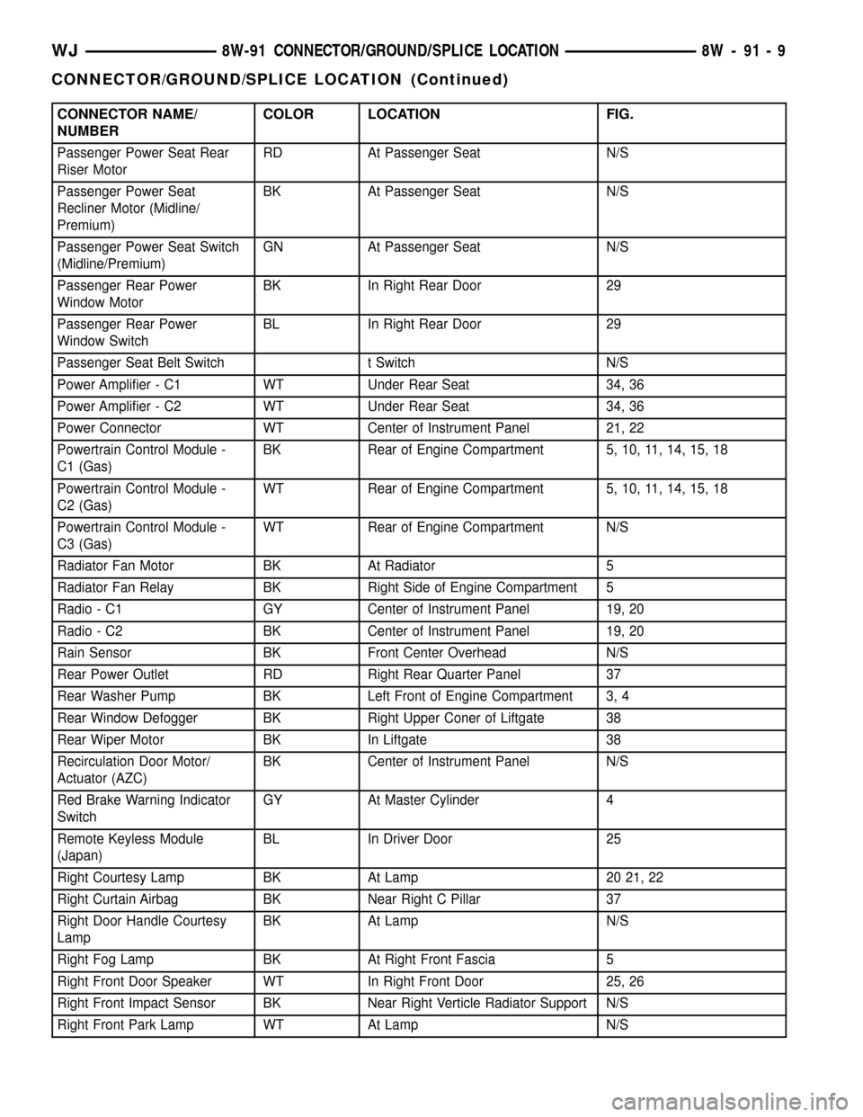
CONNECTOR NAME/
NUMBERCOLOR LOCATION FIG.
Passenger Power Seat Rear
Riser MotorRD At Passenger Seat N/S
Passenger Power Seat
Recliner Motor (Midline/
Premium)BK At Passenger Seat N/S
Passenger Power Seat Switch
(Midline/Premium)GN At Passenger Seat N/S
Passenger Rear Power
Window MotorBK In Right Rear Door 29
Passenger Rear Power
Window SwitchBL In Right Rear Door 29
Passenger Seat Belt Switch t Switch N/S
Power Amplifier - C1 WT Under Rear Seat 34, 36
Power Amplifier - C2 WT Under Rear Seat 34, 36
Power Connector WT Center of Instrument Panel 21, 22
Powertrain Control Module -
C1 (Gas)BK Rear of Engine Compartment 5, 10, 11, 14, 15, 18
Powertrain Control Module -
C2 (Gas)WT Rear of Engine Compartment 5, 10, 11, 14, 15, 18
Powertrain Control Module -
C3 (Gas)WT Rear of Engine Compartment N/S
Radiator Fan Motor BK At Radiator 5
Radiator Fan Relay BK Right Side of Engine Compartment 5
Radio - C1 GY Center of Instrument Panel 19, 20
Radio - C2 BK Center of Instrument Panel 19, 20
Rain Sensor BK Front Center Overhead N/S
Rear Power Outlet RD Right Rear Quarter Panel 37
Rear Washer Pump BK Left Front of Engine Compartment 3, 4
Rear Window Defogger BK Right Upper Coner of Liftgate 38
Rear Wiper Motor BK In Liftgate 38
Recirculation Door Motor/
Actuator (AZC)BK Center of Instrument Panel N/S
Red Brake Warning Indicator
SwitchGY At Master Cylinder 4
Remote Keyless Module
(Japan)BL In Driver Door 25
Right Courtesy Lamp BK At Lamp 20 21, 22
Right Curtain Airbag BK Near Right C Pillar 37
Right Door Handle Courtesy
LampBK At Lamp N/S
Right Fog Lamp BK At Right Front Fascia 5
Right Front Door Speaker WT In Right Front Door 25, 26
Right Front Impact Sensor BK Near Right Verticle Radiator Support N/S
Right Front Park Lamp WT At Lamp N/S
WJ8W-91 CONNECTOR/GROUND/SPLICE LOCATION 8W - 91 - 9
CONNECTOR/GROUND/SPLICE LOCATION (Continued)
Page 1185 of 2199
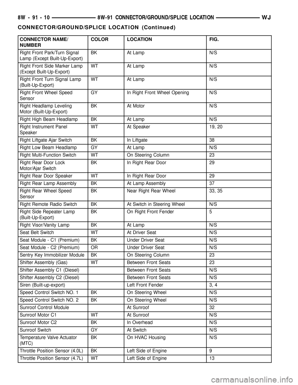
CONNECTOR NAME/
NUMBERCOLOR LOCATION FIG.
Right Front Park/Turn Signal
Lamp (Except Built-Up-Export)BK At Lamp N/S
Right Front Side Marker Lamp
(Except Built-Up-Export)WT At Lamp N/S
Right Front Turn Signal Lamp
(Built-Up-Export)WT At Lamp N/S
Right Front Wheel Speed
SensorGY In Right Front Wheel Opening N/S
Right Headlamp Leveling
Motor (Built-Up-Export)BK At Motor N/S
Right High Beam Headlamp BK At Lamp N/S
Right Instrument Panel
SpeakerWT At Speaker 19, 20
Right Liftgate Ajar Switch BK In Liftgate 38
Right Low Beam Headlamp GY At Lamp N/S
Right Multi-Function Switch WT On Steering Column 23
Right Rear Door Lock
Motor/Ajar SwitchBK In Right Rear Door 29
Right Rear Door Speaker WT In Right Rear Door 29
Right Rear Lamp Assembly BK At Lamp Assembly 37
Right Rear Wheel Speed
SensorBK Near Right Rear Wheel 33, 35
Right Remote Radio Switch BK At Switch in Steering Wheel N/S
Right Side Repeater Lamp
(Built-Up-Export)BK On Right Front Fender 5
Right Visor/Vanity Lamp BK At Lamp N/S
Seat Belt Switch WT At Driver Seat N/S
Seat Module - C1 (Premium) BK Under Driver Seat N/S
Seat Module - C2 (Premium) OR Under Driver Seat N/S
Sentry Key Immobilizer Module BK On Steering Column 23
Shifter Assembly (Gas) WT Between Front Seats 23
Shifter Assembly C1 (Diesel) Between Front Seats N/S
Shifter Assembly C2 (Diesel) Between Front Seats N/S
Siren (Built-up-export) Left Front Fender 3, 4
Speed Control Switch NO. 1 BK On Steering Wheel N/S
Speed Control Switch NO. 2 BK On Steering Wheel N/S
Sunroof Control Module At Sunroof 32
Sunroof Motor C1 WT At Sunroof N/S
Sunroof Motor C2 BK In Overhead N/S
Sunroof Switch GY At Switch N/S
Temperature Valve Actuator
(MTC)BK On HVAC Housing N/S
Throttle Position Sensor (4.0L) BK Left Side of Engine 9
Throttle Position Sensor (4.7L) WT Left Side of Engine 13
8W - 91 - 10 8W-91 CONNECTOR/GROUND/SPLICE LOCATIONWJ
CONNECTOR/GROUND/SPLICE LOCATION (Continued)
Page 1191 of 2199
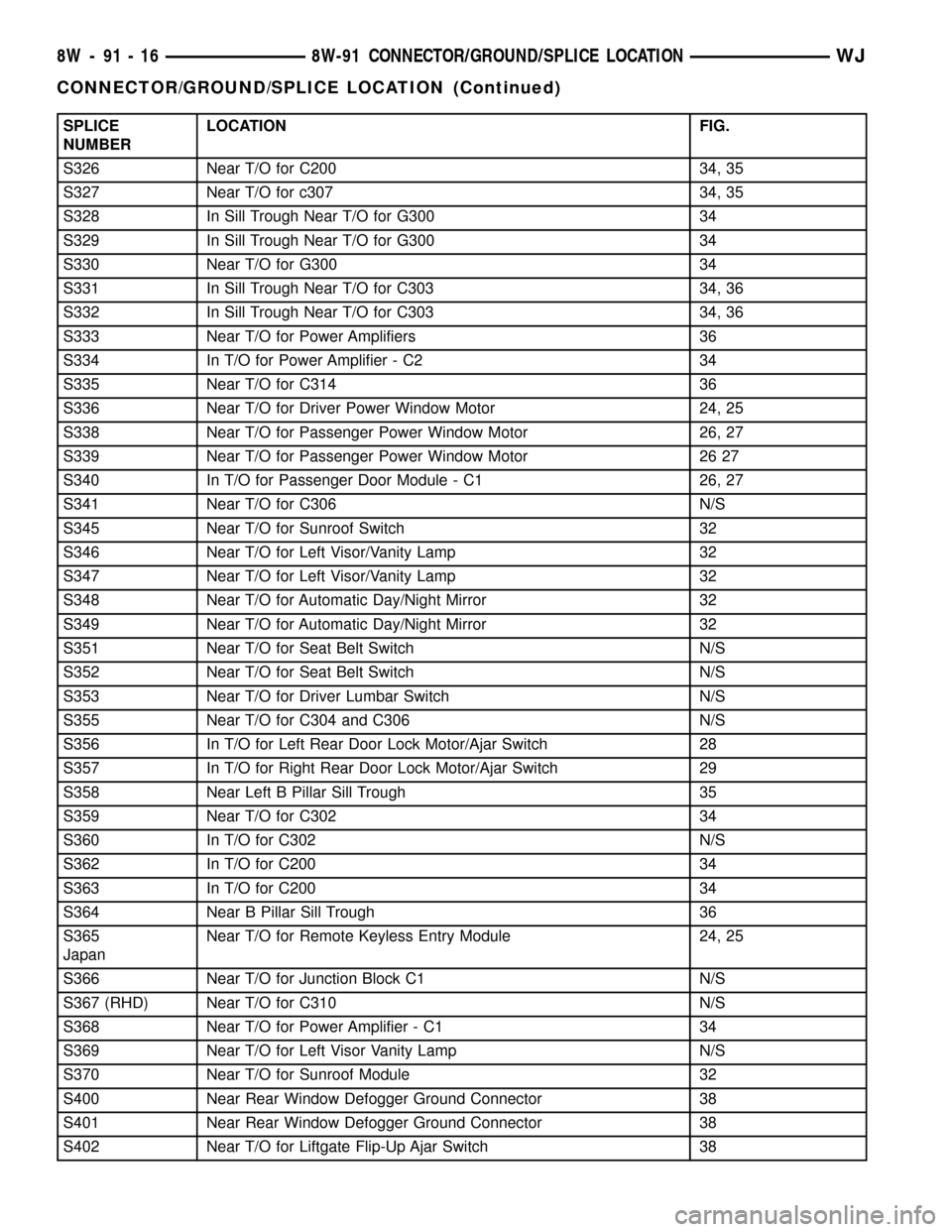
SPLICE
NUMBERLOCATION FIG.
S326 Near T/O for C200 34, 35
S327 Near T/O for c307 34, 35
S328 In Sill Trough Near T/O for G300 34
S329 In Sill Trough Near T/O for G300 34
S330 Near T/O for G300 34
S331 In Sill Trough Near T/O for C303 34, 36
S332 In Sill Trough Near T/O for C303 34, 36
S333 Near T/O for Power Amplifiers 36
S334 In T/O for Power Amplifier - C2 34
S335 Near T/O for C314 36
S336 Near T/O for Driver Power Window Motor 24, 25
S338 Near T/O for Passenger Power Window Motor 26, 27
S339 Near T/O for Passenger Power Window Motor 26 27
S340 In T/O for Passenger Door Module - C1 26, 27
S341 Near T/O for C306 N/S
S345 Near T/O for Sunroof Switch 32
S346 Near T/O for Left Visor/Vanity Lamp 32
S347 Near T/O for Left Visor/Vanity Lamp 32
S348 Near T/O for Automatic Day/Night Mirror 32
S349 Near T/O for Automatic Day/Night Mirror 32
S351 Near T/O for Seat Belt Switch N/S
S352 Near T/O for Seat Belt Switch N/S
S353 Near T/O for Driver Lumbar Switch N/S
S355 Near T/O for C304 and C306 N/S
S356 In T/O for Left Rear Door Lock Motor/Ajar Switch 28
S357 In T/O for Right Rear Door Lock Motor/Ajar Switch 29
S358 Near Left B Pillar Sill Trough 35
S359 Near T/O for C302 34
S360 In T/O for C302 N/S
S362 In T/O for C200 34
S363 In T/O for C200 34
S364 Near B Pillar Sill Trough 36
S365
JapanNear T/O for Remote Keyless Entry Module 24, 25
S366 Near T/O for Junction Block C1 N/S
S367 (RHD) Near T/O for C310 N/S
S368 Near T/O for Power Amplifier - C1 34
S369 Near T/O for Left Visor Vanity Lamp N/S
S370 Near T/O for Sunroof Module 32
S400 Near Rear Window Defogger Ground Connector 38
S401 Near Rear Window Defogger Ground Connector 38
S402 Near T/O for Liftgate Flip-Up Ajar Switch 38
8W - 91 - 16 8W-91 CONNECTOR/GROUND/SPLICE LOCATIONWJ
CONNECTOR/GROUND/SPLICE LOCATION (Continued)
Page 1214 of 2199

Fig. 23 STEERING COLUMN
Fig. 24 DRIVER DOOR LHD
WJ8W-91 CONNECTOR/GROUND/SPLICE LOCATION 8W - 91 - 39
CONNECTOR/GROUND/SPLICE LOCATION (Continued)
Page 1215 of 2199

Fig. 25 DRIVER DOOR RHD
Fig. 26 PASSENGER DOOR LHD
8W - 91 - 40 8W-91 CONNECTOR/GROUND/SPLICE LOCATIONWJ
CONNECTOR/GROUND/SPLICE LOCATION (Continued)
Page 1238 of 2199
outlet receptacle and a good ground. There should be
continuity. If OK, go to Step 4. If not OK, go to Step
5.
(4) Check for battery voltage at the insulated con-
tact located at the back of the power outlet recepta-
cle. If not OK, go to Step 5.
(5) Disconnect and isolate the battery negative
cable. Remove the instrument panel center lower
bezel. Check for continuity between the ground cir-
cuit cavity of the power outlet wire harness connector
and a good ground. There should be continuity. If
OK, go to Step 6. If not OK, repair the open ground
circuit to ground as required.
(6) Connect the battery negative cable. Check for
battery voltage at the fused B(+) circuit cavity of the
power outlet wire harness connector. If OK, replace
the faulty power outlet receptacle. If not OK, repair
the open fused B(+) circuit to the junction block fuse
as required.
REMOVAL
(1) Disconnect and isolate the battery negative
cable.
(2) Remove the center lower bezel from the instru-
ment panel. Refer toInstrument Panel Center
Lower Bezelin Body for the procedure.
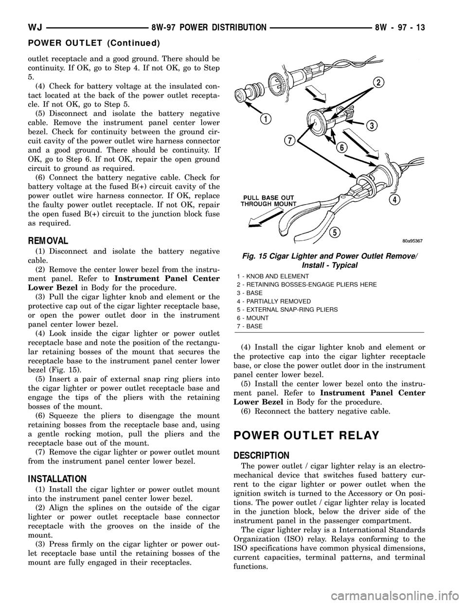
(3) Pull the cigar lighter knob and element or the
protective cap out of the cigar lighter receptacle base,
or open the power outlet door in the instrument
panel center lower bezel.
(4) Look inside the cigar lighter or power outlet
receptacle base and note the position of the rectangu-
lar retaining bosses of the mount that secures the
receptacle base to the instrument panel center lower
bezel (Fig. 15).
(5) Insert a pair of external snap ring pliers into
the cigar lighter or power outlet receptacle base and
engage the tips of the pliers with the retaining
bosses of the mount.
(6) Squeeze the pliers to disengage the mount
retaining bosses from the receptacle base and, using
a gentle rocking motion, pull the pliers and the
receptacle base out of the mount.
(7) Remove the cigar lighter or power outlet mount
from the instrument panel center lower bezel.
INSTALLATION
(1) Install the cigar lighter or power outlet mount
into the instrument panel center lower bezel.
(2) Align the splines on the outside of the cigar
lighter or power outlet receptacle base connector
receptacle with the grooves on the inside of the
mount.
(3) Press firmly on the cigar lighter or power out-
let receptacle base until the retaining bosses of the
mount are fully engaged in their receptacles.(4) Install the cigar lighter knob and element or
the protective cap into the cigar lighter receptacle
base, or close the power outlet door in the instrument
panel center lower bezel.
(5) Install the center lower bezel onto the instru-
ment panel. Refer toInstrument Panel Center
Lower Bezelin Body for the procedure.
(6) Reconnect the battery negative cable.
POWER OUTLET RELAY
DESCRIPTION
The power outlet / cigar lighter relay is an electro-
mechanical device that switches fused battery cur-
rent to the cigar lighter or power outlet when the
ignition switch is turned to the Accessory or On posi-
tions. The power outlet / cigar lighter relay is located
in the junction block, below the driver side of the
instrument panel in the passenger compartment.
The cigar lighter relay is a International Standards
Organization (ISO) relay. Relays conforming to the
ISO specifications have common physical dimensions,
current capacities, terminal patterns, and terminal
functions.
Fig. 15 Cigar Lighter and Power Outlet Remove/
Install - Typical
1 - KNOB AND ELEMENT
2 - RETAINING BOSSES-ENGAGE PLIERS HERE
3 - BASE
4 - PARTIALLY REMOVED
5 - EXTERNAL SNAP-RING PLIERS
6 - MOUNT
7 - BASE
WJ8W-97 POWER DISTRIBUTION 8W - 97 - 13
POWER OUTLET (Continued)
Page 1639 of 2199

INSPECTION
Replace the clutch discs if warped, worn, scored,
burned/charred, the lugs are damaged, or if the fac-
ing is flaking off. Replace the top and bottom pres-
sure plates if scored, warped, or cracked. Be sure the
driving lugs on the pressure and clutch plates are
also in good condition. The lugs must not be bent,
cracked or damaged in any way.
Replace the piston spring and wave spring if either
part is distorted, warped or broken.
Check the lug grooves in the clutch retainer. The
clutch and pressure plates should slide freely in the
slots. Replace the retainer if the grooves are worn or
damaged. Also check action of the check balls in the
retainer and piston. Each check ball must move
freely and not stick.
Replace the retainer bushing if worn, scored, or
doubt exists about bushing condition.
Inspect the piston and retainer seal surfaces for
nicks or scratches. Minor scratches can be removed
with crocus cloth. However, replace the piston and/or
retainer if the seal surfaces are seriously scored.
Check condition of the fiber thrust washer and
metal output shaft thrust washer. Replace either
washer if worn or damaged.
Check condition of the seal rings on the input shaft
and clutch retainer hub. Replace the seal rings only
if worn, distorted, or damaged. The input shaft front
seal ring is teflon with chamfered ends. The rear ring
is metal with interlocking ends.
Check the input shaft for wear, or damage. Replace
the shaft if worn, scored or damaged in any way.
ASSEMBLY
(1) Soak clutch discs in transmission fluid while
assembling other clutch parts.
(2) Install new seal rings on clutch retainer hub
and input shaft, if necessary, (Fig. 227) and (Fig.
228).
(a) Be sure clutch hub seal ring is fully seated in
groove and is not twisted.
(3) Lubricate splined end of input shaft and clutch
retainer with transmission fluid. Then press input
shaft into retainer (Fig. 229). Use a suitably sized
press tool to support retainer as close to input shaft
as possible.
(4) Install input shaft snap-ring (Fig. 226).
(5) Invert retainer and press input shaft in oppo-
site direction until snap-ring is seated.
(6) Install new seals on clutch piston. Be sure lip
of each seal faces interior of clutch retainer.
(7) Lubricate lip of piston seals with generous
quantity of MopartDoor Ease. Then lubricate
retainer hub and bore with light coat of transmission
fluid.
(8) Install clutch piston in retainer. Use twisting
motion to seat piston in bottom of retainer. A thin
strip of plastic (about 0.0209thick), can be used to
guide seals into place if necessary.
CAUTION: Never push the clutch piston straight in.
This will fold the seals over causing leakage and
clutch slip. In addition, never use any type of metal
tool to help ease the piston seals into place. Metal
tools will cut, shave, or score the seals.
(9) Install piston spring in retainer and on top of
piston (Fig. 230). Concave side of spring faces down-
ward (toward piston).
(10) Install wave spring in retainer (Fig. 230). Be
sure spring is completely seated in retainer groove.
(11) Install bottom pressure plate (Fig. 225).
Ridged side of plate faces downward (toward piston)
and flat side toward clutch pack.
(12) Install first clutch disc in retainer on top of
bottom pressure plate. Then install a clutch plate fol-
lowed by a clutch disc until entire clutch pack is
installed (4 discs and 3 plates are required) (Fig.
225).
(13) Install top pressure plate.
(14) Install selective snap-ring. Be sure snap-ring
is fully seated in retainer groove.
(15) Using a suitable gauge bar and dial indicator,
measure clutch pack clearance (Fig. 231).
(a) Position gauge bar across the clutch drum
with the dial indicator pointer on the pressure
plate (Fig. 231).
(b) Using two small screw drivers, lift the pres-
sure plate and release it.
Fig. 226 Removing Input Shaft Snap-Ring
1 - REAR CLUTCH RETAINER
2 - INPUT SHAFT SNAP-RING
3 - SNAP-RING PLIERS
21 - 120 AUTOMATIC TRANSMISSION - 42REWJ
REAR CLUTCH (Continued)
Page 1866 of 2199
²Unsatisfactory ride
²Vehicle drift
For proper tire pressure specification refer to the
Tire Inflation Pressure Chart provided with the vehi-
cles Owners Manual. A Certification Label on the
drivers side door pillar provides the minimum tire
and rim size for the vehicle. The label also list the
cold inflation pressure for these tires at full load
operation
Tire pressures have been chosen to provide safe
operation, vehicle stability, and a smooth ride. Tire
pressure should be checked cold once a month. Tire
pressure decreases as the ambient temperature
drops. Check tire pressure frequently when ambient
temperature varies widely.
Tire inflation pressures are cold inflation pressure.
The vehicle must sit for at least 3 hours to obtain the
correct cold inflation pressure reading. Or be drivenless than one mile after sitting for 3 hours. Tire
inflation pressures may increase from 2 to 6 pounds
per square inch (psi) during operation. Do not reduce
this normal pressure build-up.
WARNING: OVER OR UNDER INFLATED TIRES CAN
AFFECT VEHICLE HANDLING AND TREAD WEAR.
THIS MAY CAUSE THE TIRE TO FAIL SUDDENLY,
RESULTING IN LOSS OF VEHICLE CONTROL.
DESCRIPTION - TIRE PRESSURE FOR HIGH
SPEED
Where speed limits allow the vehicle to be driven
at high speeds, correct tire inflation pressure is very
important. For speeds up to and including 120 km/h
(75 mph), tires must be inflated to the pressures
shown on the tire placard. For continuous speeds in
excess of 120 km/h (75 mph), tires must be inflated
to the maximum pressure specified on the tire side-
wall.
Vehicles loaded to the maximum capacity should
not be driven at continuous speeds above 75 mph
(120 km/h).
For emergency vehicles that are driven at speeds
over 90 mph (144 km/h), special high speed tires
must be used. Consult tire manufacturer for correct
inflation pressure recommendations.
DESCRIPTION - REPLACEMENT TIRES
The original equipment tires provide a proper bal-
ance of many characteristics such as:
²Ride
²Noise
²Handling
²Durability
²Tread life
²Traction
²Rolling resistance
²Speed capability
It is recommended that tires equivalent to the orig-
inal equipment tires be used when replacement is
needed.
Failure to use equivalent replacement tires may
adversely affect the safety and handling of the vehi-
cle.
The use of oversize tires may cause interference
with vehicle components. Under extremes of suspen-
sion and steering travel, interference with vehicle
components may cause tire damage.
WARNING: FAILURE TO EQUIP THE VEHICLE WITH
TIRES HAVING ADEQUATE SPEED CAPABILITY
CAN RESULT IN SUDDEN TIRE FAILURE.
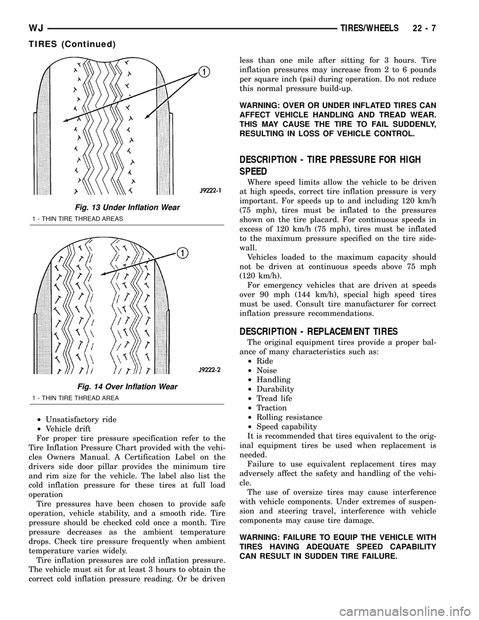
Fig. 13 Under Inflation Wear
1 - THIN TIRE THREAD AREAS
Fig. 14 Over Inflation Wear
1 - THIN TIRE THREAD AREA
WJTIRES/WHEELS 22 - 7
TIRES (Continued)
Page 1869 of 2199

SPARE TIRE
DESCRIPTION - SPARE / TEMPORARY TIRE
The temporary spare tire is designed for emer-
gency use only. The original tire should be repaired
or replaced at the first opportunity, then reinstalled.
Do not exceed speeds of 50 M.P.H. when using the
temporary spare tire. Refer to Owner's Manual for
complete details.
WHEELS
DESCRIPTION
The rim size is on the vehicle safety certification
label located on the drivers door shut face. The size
of the rim is determined by the drivetrain package.
Original equipment wheels/rims are designed for
operation up to the specified maximum vehicle capac-
ity.
All models use stamped steel, cast aluminum or
forged aluminum wheels. Every wheel has raised sec-
tions between the rim flanges and rim drop well
called safety humps (Fig. 18) .
Initial inflation of the tire forces the bead over
these raised sections. In case of rapid loss of air pres-
sure, the raised sections help hold the tire on the
wheel.
The wheel studs and nuts are designed for specific
applications. All aluminum and some steel wheels
have wheel stud nuts with an enlarged nose. This
enlarged nose is necessary to ensure proper retentionof the wheels. Do not use replacement studs or nuts
with a different design or lesser quality.
DIAGNOSIS AND TESTING - WHEEL
INSPECTION
Inspect wheels for:
²Excessive run out
²Dents or cracks
²Damaged wheel lug nut holes
²Air Leaks from any area or surface of the rim
NOTE: Do not attempt to repair a wheel by hammer-
ing, heating or welding.
If a wheel is damaged an original equipment
replacement wheel should be used. When obtaining
replacement wheels, they should be equivalent in
load carrying capacity. The diameter, width, offset,
pilot hole and bolt circle of the wheel should be the
same as the original wheel.
WARNING: FAILURE TO USE EQUIVALENT
REPLACEMENT WHEELS MAY ADVERSELY
AFFECT THE SAFETY AND HANDLING OF THE
VEHICLE. USED WHEELS ARE NOT RECOM-
MENDED. THE SERVICE HISTORY OF THE WHEEL
MAY HAVE INCLUDED SEVERE TREATMENT OR
VERY HIGH MILEAGE. THE RIM COULD FAIL WITH-
OUT WARNING.
STANDARD PROCEDURE - WHEEL
REPLACEMENT
The wheel studs and nuts are designed for specific
applications. They must be replaced with equivalent
parts. Do not use replacement parts of lesser quality
or a substitute design. All aluminum and some steel
wheels have wheel stud nuts which feature an
enlarged nose. This enlarged nose is necessary to
ensure proper retention of the aluminum wheels.
NOTE: Do not use chrome plated lug nuts with
chrome plated wheels.
Before installing the wheel, be sure to remove any
build up of corrosion on the wheel mounting surfaces.
Ensure wheels are installed with good metal-to-metal
contact. Improper installation could cause loosening
of wheel nuts. This could affect the safety and han-
dling of your vehicle.
To install the wheel, first position it properly on
the mounting surface. All wheel nuts should then be
tightened just snug. Gradually tighten them in
sequence to the proper torque specification.Never
use oil or grease on studs or nuts.
Wheels must be replaced if they have:
²Excessive runout
Fig. 18 Safety Rim
1 - FLANGE
2 - RIDGE
3 - WELL
22 - 10 TIRES/WHEELSWJ