left turn JEEP GRAND CHEROKEE 2002 WJ / 2.G Workshop Manual
[x] Cancel search | Manufacturer: JEEP, Model Year: 2002, Model line: GRAND CHEROKEE, Model: JEEP GRAND CHEROKEE 2002 WJ / 2.GPages: 2199, PDF Size: 76.01 MB
Page 1349 of 2199
(4) Remove the two spring retainer lock halves.
NOTE: the valve spring is under tension use care
when releasing the valve spring compressor.
(5) Remove the valve spring compressor.
(6) Remove the spring retainer, and the spring.
NOTE: Check for sharp edges on the keeper
grooves. Remove any burrs from the valve stem
before removing the valve from the cylinder head.
(7) Remove the valve from the cylinder head.
NOTE: The valve stem seals are common between
intake and exhaust.
(8) Remove the valve stem seal. Mark the valve for
proper installation.
TESTING VALVE SPRINGS
NOTE: Whenever the valves are removed from the
cylinder head it is recommended that the valve
springs be inspected and tested for reuse.
Inspect the valve springs for physical signs of wear
or damage. Turn table of tool C-647 until surface is
in line with the 40.69 mm (1.602 in.) mark on the
threaded stud and the zero mark on the front. Place
spring over the stud on the table and lift compress-
ing lever to set tone device. Pull on torque wrench
until Ping is heard. Take reading on torque wrench
at this instant. Multiply this reading by two. This
will give the spring load at test length. Fractional
measurements are indicated on the table for finer
adjustments. Refer to Specifications Section to obtain
specified height and allowable tensions. Replace any
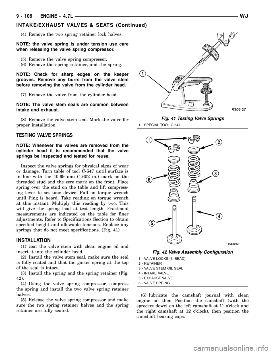
springs that do not meet specifications. (Fig. 41)
INSTALLATION
(1) coat the valve stem with clean engine oil and
insert it into the cylinder head.
(2) Install the valve stem seal. make sure the seal
is fully seated and that the garter spring at the top
of the seal is intact.
(3) Install the spring and the spring retainer (Fig.
42).
(4) Using the valve spring compressor, compress
the spring and install the two valve spring retainer
halves.
(5) Release the valve spring compressor and make
sure the two spring retainer halves and the spring
retainer are fully seated.(6) lubricate the camshaft journal with clean
engine oil then Position the camshaft (with the
sprocket dowel on the left camshaft at 11 o'clock and
the right camshaft at 12 o'clock), then position the
camshaft bearing caps.
Fig. 41 Testing Valve Springs
1 - SPECIAL TOOL C-647
Fig. 42 Valve Assembly Configuration
1 - VALVE LOCKS (3±BEAD)
2 - RETAINER
3 - VALVE STEM OIL SEAL
4 - INTAKE VALVE
5 - EXHAUST VALVE
6 - VALVE SPRING
9 - 106 ENGINE - 4.7LWJ
INTAKE/EXHAUST VALVES & SEATS (Continued)
Page 1421 of 2199

FUEL DELIVERY
DESCRIPTION
The fuel delivery system consists of:
²the fuel pump module containing the electric
fuel pump, fuel gauge sending unit (fuel level sensor)
and a separate fuel filter located at bottom of pump
module
²a separate combination fuel filter/fuel pressure
regulator
²fuel tubes/lines/hoses
²quick-connect fittings
²fuel injector rail
²fuel injectors
²fuel tank
²fuel tank filler/vent tube assembly
²fuel tank filler tube cap
²accelerator pedal
²throttle cable
OPERATION
The fuel tank assembly consists of: the fuel tank,
fuel tank shield, fuel tank straps, fuel pump module
assembly, fuel pump module locknut/gasket, and fuel
tank check valve (refer to Emission Control System
for fuel tank check valve information).
A fuel filler/vent tube assembly using a pressure/
vacuum, 1/4 turn fuel filler cap is used. The fuel
filler tube contains a flap door located below the fuel
fill cap.
Also to be considered part of the fuel system is the
evaporation control system. This is designed to
reduce the emission of fuel vapors into the atmo-
sphere. The description and function of the Evapora-
tive Control System is found in Emission Control
Systems.
Both fuel filters (at bottom of fuel pump module
and within fuel pressure regulator) are designed for
extended service. They do not require normal sched-
uled maintenance. Filters should only be replaced if
a diagnostic procedure indicates to do so.
DIAGNOSIS AND TESTING
FUEL PRESSURE LEAK DOWN TEST
Use this test in conjunction with the Fuel Pump
Pressure Test and Fuel Pump Capacity Test.
Check Valve Operation:The electric fuel pump
outlet contains a one-way check valve to prevent fuel
flow back into the tank and to maintain fuel supply
line pressure (engine warm) when pump is not oper-
ational. It is also used to keep the fuel supply line
full of gasoline when pump is not operational. After
the vehicle has cooled down, fuel pressure may drop
to 0 psi (cold fluid contracts), but liquid gasoline willremain in fuel supply line between the check valve
and fuel injectors.Fuel pressure that has
dropped to 0 psi on a cooled down vehicle
(engine off) is a normal condition.When the elec-
tric fuel pump is activated, fuel pressure should
immediately(1±2 seconds) rise to specification.
Abnormally long periods of cranking to restart a
hotengine that has been shut down for a short
period of time may be caused by:
²Fuel pressure bleeding past a fuel injector(s).
²Fuel pressure bleeding past the check valve in
the fuel pump module.
²A defective fuel filter/pressure regulator.
Two #6539, 5/16º, Fuel Line Pressure Test Adapter
Hose Tools are required for the following tests.
(1) Release fuel system pressure. Refer to Fuel
Pressure Release Procedure.
(2) Raise vehicle.
Fuel Line Identification:The fuel filter/pressure
regulator is located in front of the fuel tank and
above the rear axle. It is transversely mounted to a
chassis crossmember (left-to-right). The filter/regula-
tor is equipped with 3 fuel line fittings (2 at one end
and 1 at the other end). The single fitting facing the
left side of the vehicle is the supply line to the fuel
rail (Fig. 1) . The 2 fittings facing the right side of
the vehicle are connected to the fuel tank. Of these 2
fittings, the fitting towards thefrontis used for fuel
return to the fuel tank. The fitting towards therear
is a pressure line. Thisrearfitting must be discon-
nected for the following step.
(3) See previous step. Disconnect fuel pressure line
atrearof filter/regulator. This is a 5/169quick-con-
nect fitting (Fig. 1) . Refer to Quick-Connect Fittings
for procedures.
(4) Obtain correct Fuel Line Pressure Test Adapter
Hose Tool # 6539 for 5/16º fuel lines. Connect one
end of this Special Tool into the disconnected fuel
pressure line. Connect the other end of the Tool into
fitting on filter/regulator.
(5) Lower vehicle.
(6) Disconnect the fuel inlet line at fuel rail. Refer
to Quick-Connect Fittings for procedures. On some
engines, air cleaner housing removal may be neces-
sary before fuel line disconnection.
(7) Obtain a second Fuel Line Pressure Test
Adapter Hose Tool # 6539 for 5/16º fuel lines. Con-
nect this tool between disconnected fuel line and fuel
rail (Fig. 2) .
(8) Connect the 0-414 kPa (0-60 psi) fuel pressure
test gauge (from Gauge Set 5069) to the test port on
the appropriate Adaptor Tool.NOTE: The DRB III
Scan Tool along with the PEP module, the 500
psi pressure transducer, and the transducer-to-
test port adapter may also be used in place of
the fuel pressure gauge.
14 - 2 FUEL DELIVERYWJ
Page 1424 of 2199

SPECIAL TOOLS
FUEL SYSTEM
FUEL FILTER/PRESSURE
REGULATOR
DESCRIPTION
The combination fuel filter/pressure regulator is
located in front of the fuel tank and above the rear
axle (Fig. 3). It is transversely mounted to a chassis
crossmember (left-to-right).Fuel Line Identifica-
tion:The filter/regulator is equipped with 3 fuel line
fittings (2 at one end and 1 at the other end). The
single fitting facing the left side of the vehicle is the
supply line to the fuel rail (Fig. 3). The 2 fittings fac-
ing the right side of the vehicle are connected to the
fuel tank. Of these 2 fittings, the fitting towards the
frontis used for fuel return to the fuel tank. The fit-
ting towards therearis a pressure line.
OPERATION
Fuel Pressure Regulator Operation:The pres-
sure regulator is a mechanical device that is not con-
trolled by engine vacuum or the Powertrain Control
Module (PCM).
Spanner WrenchÐ6856
FITTING, AIR METERING - 6714
Adapters, Fuel Pressure TestÐ6539 and/or 6631
O2S (Oxygen Sensor) Remover/InstallerÐC-4907
Test Kit, Fuel PressureÐ5069
Test Kit, Fuel PressureÐC-4799-B
Fuel Line Removal ToolÐ6782
WJFUEL DELIVERY 14 - 5
FUEL DELIVERY (Continued)
Page 1439 of 2199

(19) Disconnect fuel return line at fuel filter/fuel
pressure regulator (Fig. 36). Refer to Quick-Connect
Fittings for procedures.
(20) Disconnect fuel pressure line at fuel filter/fuel
pressure regulator (Fig. 36). Refer to Quick-Connect
Fittings for procedures.
(21) Disconnect EVAP canister vent line near front
of tank (Fig. 36).
(22) Disconnect fuel pump module electrical con-
nector (pigtail harness) near front of tank (Fig. 36).
Harness connector is clipped to body.
(23) Remove left / front tank support bracket bolt
at frame (Fig. 37).
(24)WITHOUT TRAILER HITCH:Remove tank-
to-frame mounting bolts (Fig. 39). Remove rear tank
support bracket bolts at frame (Fig. 38). Carefully
lower tank until clear of vehicle. Place tank on floor.
(25)WITH TRAILER HITCH:Remove tank /
hitch mounting bolts (Fig. 40). Carefully lower tank
until clear of vehicle. Place tank on floor.
(26) If necessary, separate skid plate from fuel
tank by removing 2 fuel tank strap nuts (Fig. 39) and
remove 2 tank straps.
(27) If fuel pump module removal is necessary,
refer to Fuel Pump Module Removal/Installation.
(28) If hoses are to be removed at fuel tank end,
note painted alignment (indexing) markings on
hoses, and molded indexing tangs on tank before
removal. Remove hoses.
(29) If necessary, remove 3 fuel filler tube assem-
bly mounting bolts (Fig. 41) and remove fuel filler
tube.
INSTALLATION
CAUTION: HANDLE EVAP, LDP AND ORVR VAPOR /
VACUUM LINES VERY CAREFULLY. THESE LINES
AND HOSES MUST BE FIRMLY CONNECTED.
CHECK THE VAPOR/VACUUM LINES AT THE LDP,
LDP FILTER, EVAP CANISTER, EVAP CANISTER
PURGE SOLENOID AND ORVR COMPONENTS FOR
DAMAGE OR LEAKS. IF A LEAK IS PRESENT, A
DIAGNOSTIC TROUBLE CODE (DTC) MAY BE SET.
(1) If necessary, position fuel filler tube assembly
to body. Install 3 bolts and tighten to 2 N´m (15 in.
lbs.) torque.
(2) If necessary, connect quick-connect fittings to
fuel pump module.
(3) If fuel pump module is being installed, refer to
Fuel Pump Module Removal/Installation.
(4) Install fuel fill/vent hoses to tank fittings. To
prevent hoses from kinking, rotate each hose until
painted indexing mark on hose is aligned to molded
indexing tang on tank.
(5) Install hose clamps to hoses. Refer to Torque
Specifications.(6) If necessary, position fuel tank into skid plate.
Install 2 tank straps and 2 strap nuts (Fig. 39). Refer
to Torque Specifications.
(7) Position fuel tank / skid plate assembly to
hydraulic jack.
(8) Raise tank into position to frame.
(9)WITH TRAILER HITCH:Position trailer
hitch and tow hooks (Fig. 40) to bottom of fuel tank.
Install bolts and nuts loosely.
(10)WITHOUT TRAILER HITCH:Install 2 rear
tank support brackets and bolts (Fig. 38). Install
tank-to-frame bolts. Do not tighten bolts / nuts at
this time.
(11) Install 1 left / front tank support bracket and
bolts / nuts (Fig. 37). Do not tighten bolts / nuts at
this time.
(12) Be sure fuel tank is properly aligned to frame
and body. Tighten all tank, tow hook and trailer
hitch bolts / nuts except for 3 support brackets.
Tighten all 3 (2 rear and 1 left / front) support
bracket bolts / nuts last. Refer to Torque Specifica-
tions.
(13)
(14) Connect fuel pump module pigtail harness
electrical connector near front of tank.
(15) Connect both fuel lines to fuel filter/fuel pres-
sure regulator. Refer to Quick-Connect Fittings for
procedures.
(16) Connect EVAP hose near front of tank.
(17) Position rear axle vent hose and install new
tie strap (Fig. 32).
(18) Install heat shield nuts / bolts (Fig. 35). Refer
to Torque Specifications.
(19) Connect ORVR hose elbow (Fig. 33) to top of
EVAP canister.
(20) Connect fuel vent hose to fuel vent tube (Fig.
32).
(21) Install fuel fill hose and clamp to fuel fill tube
(Fig. 32).
(22) Install 3 LDP mounting bolts (Fig. 29).
(23) While raising support bracket, connect LDP
wiring clip (Fig. 31). Install front section of two-piece
support bracket to rear section with 3 attaching bolts
located on bottom of support bracket (Fig. 30).
(24) Install support bracket brace bolt (Fig. 30).
(25) Tighten 2 support bracket nuts at frame rail
(Fig. 29).
(26) Install fuel tank-to-rear bumper fascia clips
(Fig. 34).
(27) Using new plastic rivets, install stone shield
behind left/rear wheel (Fig. 28).
(28) Install left rear wheel/tire.
(29) Lower vehicle and connect negative battery
cable to battery.
(30) Fill tank with fuel and check for leaks.
14 - 20 FUEL DELIVERYWJ
FUEL TANK (Continued)
Page 1461 of 2199
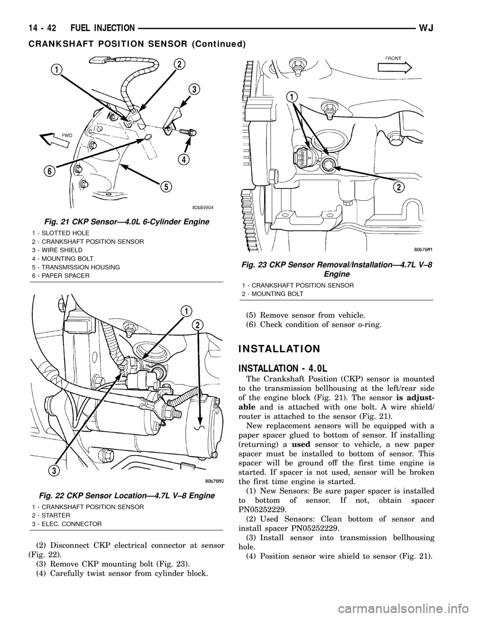
(2) Disconnect CKP electrical connector at sensor
(Fig. 22).
(3) Remove CKP mounting bolt (Fig. 23).
(4) Carefully twist sensor from cylinder block.(5) Remove sensor from vehicle.
(6) Check condition of sensor o-ring.
INSTALLATION
INSTALLATION - 4.0L
The Crankshaft Position (CKP) sensor is mounted
to the transmission bellhousing at the left/rear side
of the engine block (Fig. 21). The sensoris adjust-
ableand is attached with one bolt. A wire shield/
router is attached to the sensor (Fig. 21).
New replacement sensors will be equipped with a
paper spacer glued to bottom of sensor. If installing
(returning) ausedsensor to vehicle, a new paper
spacer must be installed to bottom of sensor. This
spacer will be ground off the first time engine is
started. If spacer is not used, sensor will be broken
the first time engine is started.
(1) New Sensors: Be sure paper spacer is installed
to bottom of sensor. If not, obtain spacer
PN05252229.
(2) Used Sensors: Clean bottom of sensor and
install spacer PN05252229.
(3) Install sensor into transmission bellhousing
hole.
(4) Position sensor wire shield to sensor (Fig. 21).
Fig. 21 CKP SensorÐ4.0L 6-Cylinder Engine
1 - SLOTTED HOLE
2 - CRANKSHAFT POSITION SENSOR
3 - WIRE SHIELD
4 - MOUNTING BOLT
5 - TRANSMISSION HOUSING
6 - PAPER SPACER
Fig. 22 CKP Sensor LocationÐ4.7L V±8 Engine
1 - CRANKSHAFT POSITION SENSOR
2-STARTER
3 - ELEC. CONNECTOR
Fig. 23 CKP Sensor Removal/InstallationÐ4.7L V±8
Engine
1 - CRANKSHAFT POSITION SENSOR
2 - MOUNTING BOLT
14 - 42 FUEL INJECTIONWJ
CRANKSHAFT POSITION SENSOR (Continued)
Page 1465 of 2199
INSTALLATION
INSTALLATION - 4.0L
The IAC motor is located on the throttle body.
(1) Install IAC motor to throttle body.
(2) Install and tighten two mounting bolts (screws)
to 7 N´m (60 in. lbs.) torque.
(3) Install electrical connector.
(4) Install air cleaner duct/air box to throttle body.
INSTALLATION - 4.7L
(1) Install IAC motor to throttle body.
(2) Install and tighten two mounting bolts (screws)
to 7 N´m (60 in. lbs.) torque.
(3) Install electrical connector.
(4) Install air duct/air box to throttle body.
INTAKE AIR TEMPERATURE
SENSOR
DESCRIPTION
The 2±wire Intake Manifold Air Temperature (IAT)
sensor is installed in the intake manifold with the
sensor element extending into the air stream.
The IAT sensor is a two-wire Negative Thermal
Coefficient (NTC) sensor. Meaning, as intake mani-
fold temperature increases, resistance (voltage) in the
sensor decreases. As temperature decreases, resis-
tance (voltage) in the sensor increases.
OPERATION
The IAT sensor provides an input voltage to the
Powertrain Control Module (PCM) indicating the
density of the air entering the intake manifold based
upon intake manifold temperature. At key-on, a
5±volt power circuit is supplied to the sensor from
the PCM. The sensor is grounded at the PCM
through a low-noise, sensor-return circuit.
The PCM uses this input to calculate the following:
²Injector pulse-width
²Adjustment of spark timing (to help prevent
spark knock with high intake manifold air-charge
temperatures)
The resistance values of the IAT sensor is the same
as for the Engine Coolant Temperature (ECT) sensor.
REMOVAL
REMOVAL - 4.0L
The Intake Manifold Air Temperature (IAT) sensor
is installed into the intake manifold plenum near the
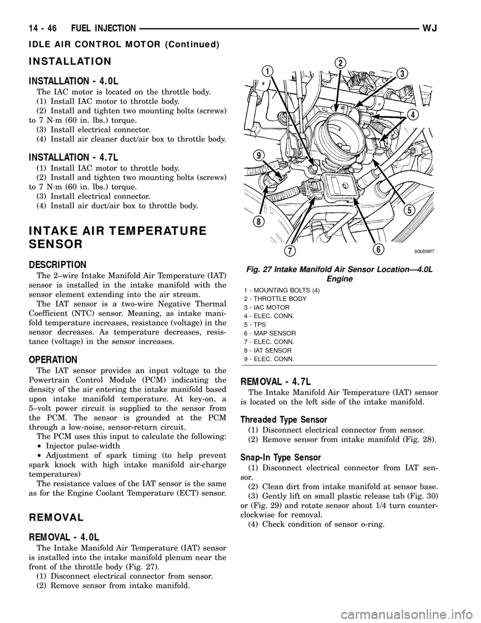
front of the throttle body (Fig. 27).
(1) Disconnect electrical connector from sensor.
(2) Remove sensor from intake manifold.
REMOVAL - 4.7L
The Intake Manifold Air Temperature (IAT) sensor
is located on the left side of the intake manifold.
Threaded Type Sensor
(1) Disconnect electrical connector from sensor.
(2) Remove sensor from intake manifold (Fig. 28).
Snap-In Type Sensor
(1) Disconnect electrical connector from IAT sen-
sor.
(2) Clean dirt from intake manifold at sensor base.
(3) Gently lift on small plastic release tab (Fig. 30)
or (Fig. 29) and rotate sensor about 1/4 turn counter-
clockwise for removal.
(4) Check condition of sensor o-ring.
Fig. 27 Intake Manifold Air Sensor LocationÐ4.0L
Engine
1 - MOUNTING BOLTS (4)
2 - THROTTLE BODY
3 - IAC MOTOR
4 - ELEC. CONN.
5 - TPS
6 - MAP SENSOR
7 - ELEC. CONN.
8 - IAT SENSOR
9 - ELEC. CONN.
14 - 46 FUEL INJECTIONWJ
IDLE AIR CONTROL MOTOR (Continued)
Page 1469 of 2199

The other two heater elements (downstream sen-
sors 1/2 and 2/2) are controlled by the downstream
heater relay through output signals from the PCM.
To avoid a large simultaneous current surge, power
is delayed to the 2 downstream heater elements by
the PCM for approximately 2 seconds.
REMOVAL
(1) Remove PDC cover.
(2) Remove relay from PDC.
(3) Check condition of relay terminals and PDC
connector terminals for damage or corrosion. Repair
if necessary before installing relay.
(4) Check for pin height (pin height should be the
same for all terminals within the PDC connector).
Repair if necessary before installing relay.
INSTALLATION
(1) Install relay to PDC.
(2) Install cover to PDC.
O2S SENSOR
DESCRIPTION
The Oxygen Sensors (O2S) are attached to, and
protrude into the vehicle exhaust system. Depending
on the emission package, the vehicle may use a total
of either 2 or 4 sensors.
Federal Emissions Package:Two sensors are
used: upstream (referred to as 1/1) and downstream
(referred to as 1/2). With this emission package, the
upstream sensor (1/1) is located just before the main
catalytic convertor. The downstream sensor (1/2) is
located just after the main catalytic convertor.
4.7L V-8 With California Emissions Package:
On this emissions package, 4 sensors are used: 2
upstream (referred to as 1/1 and 2/1) and 2 down-
stream (referred to as 1/2 and 2/2). With this emis-
sion package, the right upstream sensor (2/1) is
located in the right exhaust downpipe just before the
mini-catalytic convertor. The left upstream sensor
(1/1) is located in the left exhaust downpipe just
before the mini-catalytic convertor. The right down-
stream sensor (2/2) is located in the right exhaust
downpipe just after the mini-catalytic convertor, and
before the main catalytic convertor. The left down-
stream sensor (1/2) is located in the left exhaust
downpipe just after the mini-catalytic convertor, and
before the main catalytic convertor.
4.0L 6±Cylinder With California Emissions
Package:On this emissions package, 4 sensors are
used: 2 upstream (referred to as 1/1 and 2/1) and 2
downstream (referred to as 1/2 and 2/2). With this
emission package, the rear/upper upstream sensor
(2/1) is located in the exhaust downpipe just beforethe rear mini-catalytic convertor. The front/upper
upstream sensor (1/1) is located in the exhaust down-
pipe just before the front mini-catalytic convertor.
The rear/lower downstream sensor (2/2) is located in
the exhaust downpipe just after the rear mini-cata-
lytic convertor, and before the main catalytic conver-
tor. The front/lower downstream sensor (1/2) is
located in the exhaust downpipe just after the front
mini-catalytic convertor, and before the main cata-
lytic convertor.
OPERATION
An O2 sensor is a galvanic battery that provides
the PCM with a voltage signal (0-1 volt) inversely
proportional to the amount of oxygen in the exhaust.
In other words, if the oxygen content is low, the volt-
age output is high; if the oxygen content is high the
output voltage is low. The PCM uses this information
to adjust injector pulse-width to achieve the
14.7±to±1 air/fuel ratio necessary for proper engine
operation and to control emissions.
The O2 sensor must have a source of oxygen from
outside of the exhaust stream for comparison. Cur-
rent O2 sensors receive their fresh oxygen (outside
air) supply through the O2 sensor case housing.
Four wires (circuits) are used on each O2 sensor: a
12±volt feed circuit for the sensor heating element; a
ground circuit for the heater element; a low-noise
sensor return circuit to the PCM, and an input cir-
cuit from the sensor back to the PCM to detect sen-
sor operation.
Oxygen Sensor Heaters/Heater Relays:
Depending on the emissions package, the heating ele-
ments within the sensors will be supplied voltage
from either the ASD relay, or 2 separate oxygen sen-
sor relays. Refer to Wiring Diagrams to determine
which relays are used.
The O2 sensor uses a Positive Thermal Co-efficient
(PTC) heater element. As temperature increases,
resistance increases. At ambient temperatures
around 70ÉF, the resistance of the heating element is
approximately 4.5 ohms on 4.0L engines. It is
approximately 13.5 ohms on the 4.7L engine. As the
sensor's temperature increases, resistance in the
heater element increases. This allows the heater to
maintain the optimum operating temperature of
approximately 930É-1100ÉF (500É-600É C). Although
the sensors operate the same, there are physical dif-
ferences, due to the environment that they operate
in, that keep them from being interchangeable.
Maintaining correct sensor temperature at all
times allows the system to enter into closed loop
operation sooner. Also, it allows the system to remain
in closed loop operation during periods of extended
idle.
14 - 50 FUEL INJECTIONWJ
O2S HEATER RELAY (Continued)
Page 1482 of 2199
(8) Start engine and let idle long enough to circu-
late power steering fluid through flow/pressure test
gauge.
(9) Shut off the engine and check the fluid level,
add fluid as necessary. Start engine again and let
idle.
(10) The initial pressure reading should be
345-552 kPa (50-80 psi). If pressure is higher inspect
the hoses for restrictions and repair as necessary.
(11) Increase the engine speed to 1500 RPM and
read the flow meter. The reading should be 2.4 - 2.8
GPM, if the reading is below this specification the
pump should be replaced.
CAUTION: This next step involves testing maximum
pump pressure output and flow control valve oper-
ation. Do not leave valve closed for more than three
seconds as the pump could be damaged.
(12) Close valve fully three times for three seconds
and record highest pressure indicated each time.All
three readings must be at pump relief pressure
specifications and within 345 kPa (50 psi) of
each other.
²Pressures above specifications but not within
345 kPa (50 psi) of each other, replace pump.
²Pressures within 345 kPa (50 psi) of each other
but below specifications, replace pump.
CAUTION: Do not force the pump to operate against
the stops for more than 2 to 4 seconds at a time
because, pump damage will result.
(13) Open the test valve and turn the steering
wheel to the extreme left and right positions against
the stops. Record the highest pressure reading at
each position. Compare readings to the pump specifi-
cations chart. If pressures readings are not within 50
psi. of each other, the gear is leaking internally and
must be repaired.
GEAR INLET SPECIFICATIONS 4.0L & 4.7L
ENGINERELIEF
PRESSURE 50FLOW RATE
(GPM)
4.0L 9653 kPa (1400 psi)
1500 RPM 2.4 - 2.8
GPM
4.7L 9653 kPa (1450 psi)
PUMP MOTOR SPECIFICATIONS 4.7L
ENGINERELIEF
PRESSURE 50FLOW RATE
(GPM)
4.7L 9653 kPa (1900 psi)1100 RPM 2.4-2.8
GPM Minium
@ 200 psi
DIAGNOSIS AND TESTING - 4.7L -
HYDRAULIC
The following procedures are used to test the oper-
ation of the power steering and hydraulic fan sys-
tems on the vehicle. This test will provide the gallons
per minute (GPM) or flow rate of the power steering
pump along with any maximum relief pressure. Per-
form test anytime a power steering system problem
is present. This test will determine if the power
steering pump, hydraulic fan, and power steering
gear are not functioning properly. It will also deter-
mine if the flow coming out of the hydraulic fan
motor is sufficient for the power steering gear. The
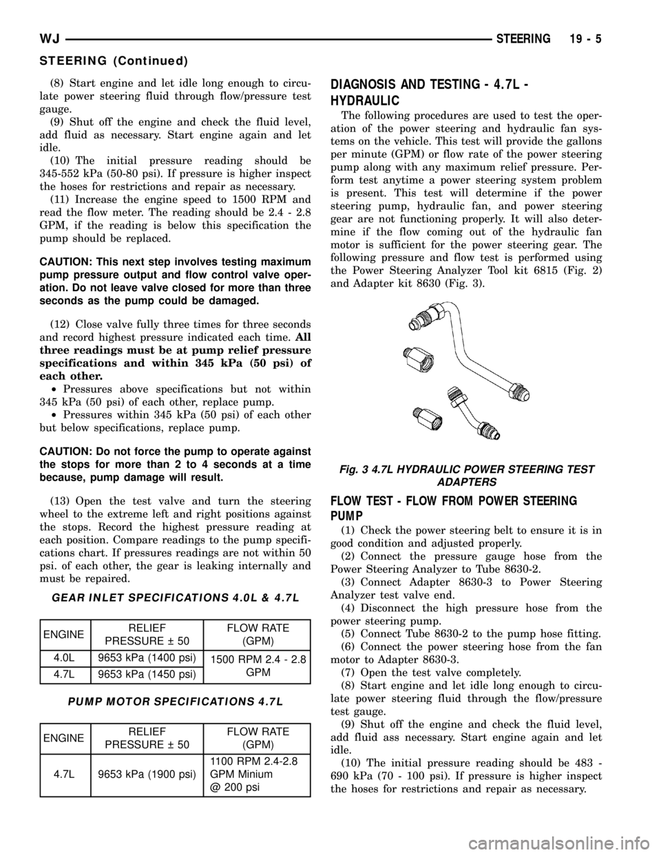
following pressure and flow test is performed using
the Power Steering Analyzer Tool kit 6815 (Fig. 2)
and Adapter kit 8630 (Fig. 3).
FLOW TEST - FLOW FROM POWER STEERING
PUMP
(1) Check the power steering belt to ensure it is in
good condition and adjusted properly.
(2) Connect the pressure gauge hose from the
Power Steering Analyzer to Tube 8630-2.
(3) Connect Adapter 8630-3 to Power Steering
Analyzer test valve end.
(4) Disconnect the high pressure hose from the
power steering pump.
(5) Connect Tube 8630-2 to the pump hose fitting.
(6) Connect the power steering hose from the fan
motor to Adapter 8630-3.
(7) Open the test valve completely.
(8) Start engine and let idle long enough to circu-
late power steering fluid through the flow/pressure
test gauge.
(9) Shut off the engine and check the fluid level,
add fluid ass necessary. Start engine again and let
idle.
(10) The initial pressure reading should be 483 -
690 kPa (70 - 100 psi). If pressure is higher inspect
the hoses for restrictions and repair as necessary.
Fig. 3 4.7L HYDRAULIC POWER STEERING TEST
ADAPTERS
WJSTEERING 19 - 5
STEERING (Continued)
Page 1483 of 2199
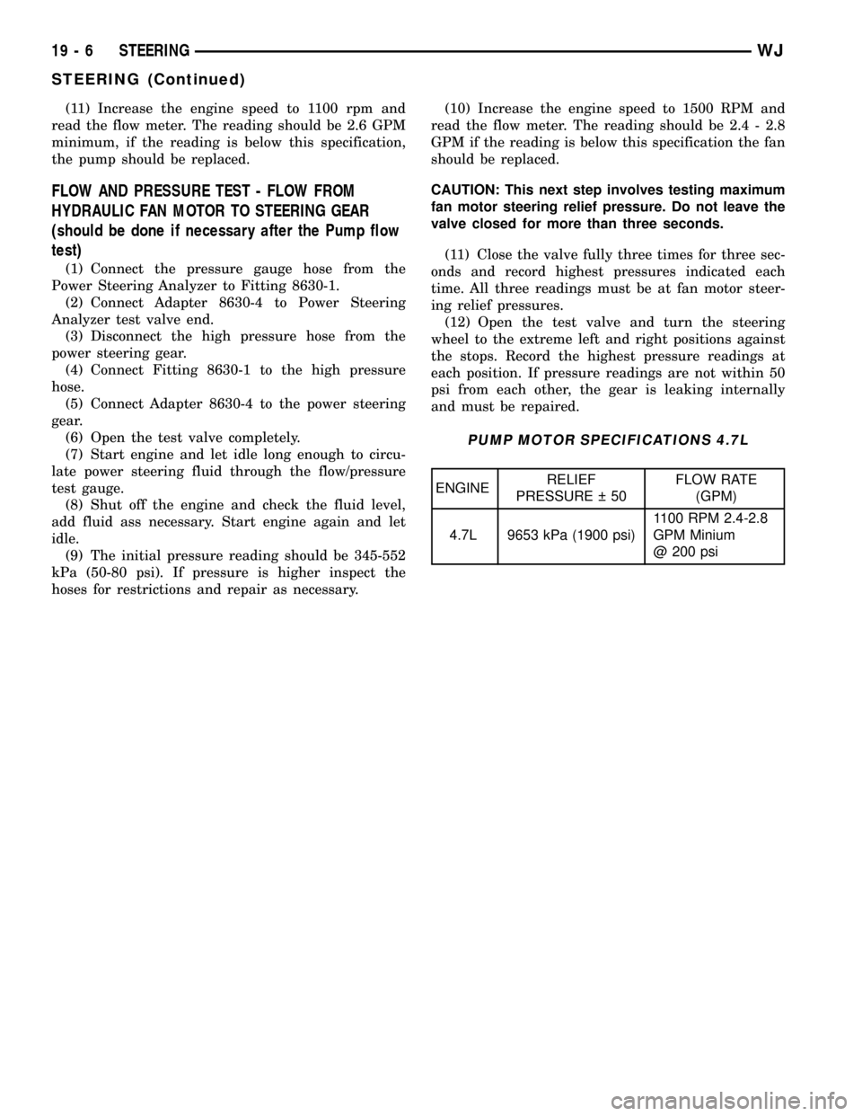
(11) Increase the engine speed to 1100 rpm and
read the flow meter. The reading should be 2.6 GPM
minimum, if the reading is below this specification,
the pump should be replaced.
FLOW AND PRESSURE TEST - FLOW FROM
HYDRAULIC FAN MOTOR TO STEERING GEAR
(should be done if necessary after the Pump flow
test)
(1) Connect the pressure gauge hose from the
Power Steering Analyzer to Fitting 8630-1.
(2) Connect Adapter 8630-4 to Power Steering
Analyzer test valve end.
(3) Disconnect the high pressure hose from the
power steering gear.
(4) Connect Fitting 8630-1 to the high pressure
hose.
(5) Connect Adapter 8630-4 to the power steering
gear.
(6) Open the test valve completely.
(7) Start engine and let idle long enough to circu-
late power steering fluid through the flow/pressure
test gauge.
(8) Shut off the engine and check the fluid level,
add fluid ass necessary. Start engine again and let
idle.
(9) The initial pressure reading should be 345-552
kPa (50-80 psi). If pressure is higher inspect the
hoses for restrictions and repair as necessary.(10) Increase the engine speed to 1500 RPM and
read the flow meter. The reading should be 2.4 - 2.8
GPM if the reading is below this specification the fan
should be replaced.
CAUTION: This next step involves testing maximum
fan motor steering relief pressure. Do not leave the
valve closed for more than three seconds.
(11) Close the valve fully three times for three sec-
onds and record highest pressures indicated each
time. All three readings must be at fan motor steer-
ing relief pressures.
(12) Open the test valve and turn the steering
wheel to the extreme left and right positions against
the stops. Record the highest pressure readings at
each position. If pressure readings are not within 50
psi from each other, the gear is leaking internally
and must be repaired.
PUMP MOTOR SPECIFICATIONS 4.7L
ENGINERELIEF
PRESSURE 50FLOW RATE
(GPM)
4.7L 9653 kPa (1900 psi)1100 RPM 2.4-2.8
GPM Minium
@ 200 psi
19 - 6 STEERINGWJ
STEERING (Continued)
Page 1493 of 2199

GEAR
TABLE OF CONTENTS
page page
GEAR
DESCRIPTION.........................16
OPERATION...........................16
REMOVAL.............................16
INSTALLATION.........................16
ADJUSTMENTS
STEERING GEAR.....................18
SPECIFICATIONS
POWER STEERING GEAR..............18
SPECIAL TOOLS
POWER STEERING GEAR..............19
PITMAN SHAFT
REMOVAL.............................20INSTALLATION.........................20
PITMAN SHAFT BEARING
REMOVAL.............................22
INSTALLATION.........................22
PITMAN SHAFT SEAL
REMOVAL.............................22
INSTALLATION.........................23
RACK PISTON/VALVE ASSEMBLY
REMOVAL.............................23
INSTALLATION.........................25
STUB SHAFT HOUSING
REMOVAL.............................25
INSTALLATION.........................25
GEAR
DESCRIPTION
The power steering gear is a recirculating ball type
gear (Fig. 1) .
The following gear components can be serviced:
²Pitman Shaft and Cover
²Pitman Shaft Bearings
²Pitman Shaft Oil Seal/Dust Seal
²Stud Shaft Housing with Seal
²O-Rings and Teflon Rings
NOTE: If rack piston assembly is damaged the gear
must be replaced.
OPERATION
The gear acts as a rolling thread between the
worm shaft and rack piston. The worm shaft is sup-
ported by a thrust bearing at the lower end and a
bearing assembly at the upper end. When the worm
shaft is turned the rack piston moves. The rack pis-
ton teeth mesh with the pitman shaft. Turning the
worm shaft turns the pitman shaft, which turns the
steering linkage.
REMOVAL
(1) Place the front wheels in the straight ahead
position with the steering wheel centered and locked.
(2) Remove the air cleaner housing,(Refer to 9 -
ENGINE/AIR INTAKE SYSTEM/AIR CLEANER
HOUSING - REMOVAL).
(3) Drain or siphon the power steering system.(4) Remove the pressure and return lines (Fig.
2)from the steering gear. Refer to hose removal in
this section.
(5) Remove the column coupler shaft bolt (Fig.
2)and remove the shaft from the gear.
(6) Raise and support the vehicle.
(7) Remove the left front wheel and tire assembly.
(8) Remove the pitman arm from gear with Puller
C-4150A.
(9) Remove the windshield washer reservoir,(Refer
to 8 - ELECTRICAL/WIPERS/WASHERS/WASHER
RESERVOIR - REMOVAL).
(10) Remove the steering gear mounting bolts.
Remove the steering gear out of the engine compart-
ment (Fig. 3).
INSTALLATION
(1) Position the steering gear on the frame rail and
install the bolts. Tighten the bolts to 108 N´m (80 ft.
lbs.) torque.
(2) Install the pitman arm and tighten nut to 251
N´m (185 ft. lbs.).
(3) Install windshield washer reservoir,(Refer to 8 -
ELECTRICAL/WIPERS/WASHERS/WASHER RES-
ERVOIR - INSTALLATION).
(4) Install the wheel and tire assembly.
(5) Remove the support and lower the vehicle.
(6) Install the pressure and return hoses to the
steering gear and tighten to 20-38 N´m (14-28 ft.
lbs.).
(7) Install the column coupler shaft.
(8) Install the air cleaner housing,(Refer to 9 -
ENGINE/AIR INTAKE SYSTEM/AIR CLEANER
HOUSING - INSTALLATION).
19 - 16 GEARWJ