Gear JEEP GRAND CHEROKEE 2002 WJ / 2.G Workshop Manual
[x] Cancel search | Manufacturer: JEEP, Model Year: 2002, Model line: GRAND CHEROKEE, Model: JEEP GRAND CHEROKEE 2002 WJ / 2.GPages: 2199, PDF Size: 76.01 MB
Page 1342 of 2199
(19) Remove the retaining bolt and the camshaft
drive gear.
CAUTION: Do not allow the engine to rotate. severe
damage to the valve train can occur.
CAUTION: Do not overlook the four smaller bolts at
the front of the cylinder head. Do not attempt to
remove the cylinder head without removing these
four bolts.
CAUTION: Do not hold or pry on the camshaft tar-
get wheel for any reason. A damaged target wheel
can result in a vehicle no start condition.
NOTE: The cylinder head is attached to the cylinder
block with fourteen bolts.
(20) Remove the cylinder head retaining bolts.
(21) Remove the cylinder head and gasket. Discard
the gasket.
CAUTION: Do not lay the cylinder head on its gas-
ket sealing surface, do to the design of the cylinder
head gasket any distortion to the cylinder head
sealing surface may prevent the gasket from prop-
erly sealing resulting in leaks.
CLEANING
To ensure engine gasket sealing, proper surface
preparation must be performed, especially with the
use of aluminum engine components. (Refer to 9 -
ENGINE - STANDARD PROCEDURE)
INSPECTION
(1) Inspect the cylinder head for out-of-flatness,
using a straightedge and a feeler gauge. If tolerances
exceed 0.0508 mm (0.002 in.) replace the cylinder
head.
(2) Inspect the valve seats for damage. Service the
valve seats as necessary.
(3) Inspect the valve guides for wear, cracks or
looseness. If either condition exist, replace the cylin-
der head.
INSTALLATION
NOTE: The cylinder head bolts are tightened using
a torque plus angle procedure. The bolts must be
examined BEFORE reuse. If the threads are necked
down the bolts should be replaced.
Necking can be checked by holding a straight edge
against the threads. If all the threads do not contact
the scale, the bolt should be replaced (Fig. 13).
CAUTION: When cleaning cylinder head and cylin-
der block surfaces, DO NOT use a metal scraper
because the surfaces could be cut or ground. Use
only a wooden or plastic scraper.
(1) Clean the cylinder head and cylinder block
mating surfaces (Refer to 9 - ENGINE - STANDARD
PROCEDURE).
(2) Position the new cylinder head gasket on the
locating dowels.
CAUTION: When installing cylinder head, use care
not damage the tensioner arm or the guide arm.
(3) Position the cylinder head onto the cylinder
block. Make sure the cylinder head seats fully over
the locating dowels.
NOTE: The four smaller cylinder head mounting
bolts require sealant to be added to them before
installing. Failure to do so may cause leaks.
(4) Lubricate the cylinder head bolt threads with
clean engine oil and install the ten M10 bolts.
(5) Coat the four M8 cylinder head bolts with
Mopar Lock and Seal Adhesivethen install the
bolts.
NOTE: The cylinder head bolts are tightened using
an angle torque procedure, however, the bolts are
not a torque-to-yield design.
(6) Tighten the bolts in sequence (Fig. 30) using
the following steps and torque values:
²Step 1: Tighten bolts 1±10, 27 N´m (20 ft. lbs.).
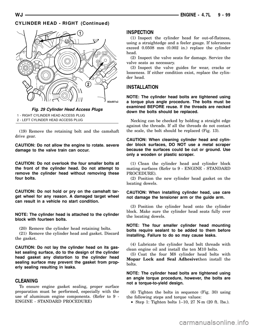
Fig. 29 Cylinder Head Access Plugs
1 - RIGHT CYLINDER HEAD ACCESS PLUG
2 - LEFT CYLINDER HEAD ACCESS PLUG
WJENGINE - 4.7L 9 - 99
CYLINDER HEAD - RIGHT (Continued)
Page 1345 of 2199
INSTALLATION
(1) Lubricate camshaft journals with clean engine
oil.
NOTE: Position the right side camshaft so that the
camshaft sprocket dowel is near the 10 o'clock
position, This will place the camshaft at the neutral
position easing the installation of the camshaft
bearing caps.
(2) Position the camshaft into the cylinder head.
(3) Install the camshaft bearing caps, hand tighten
the retaining bolts.
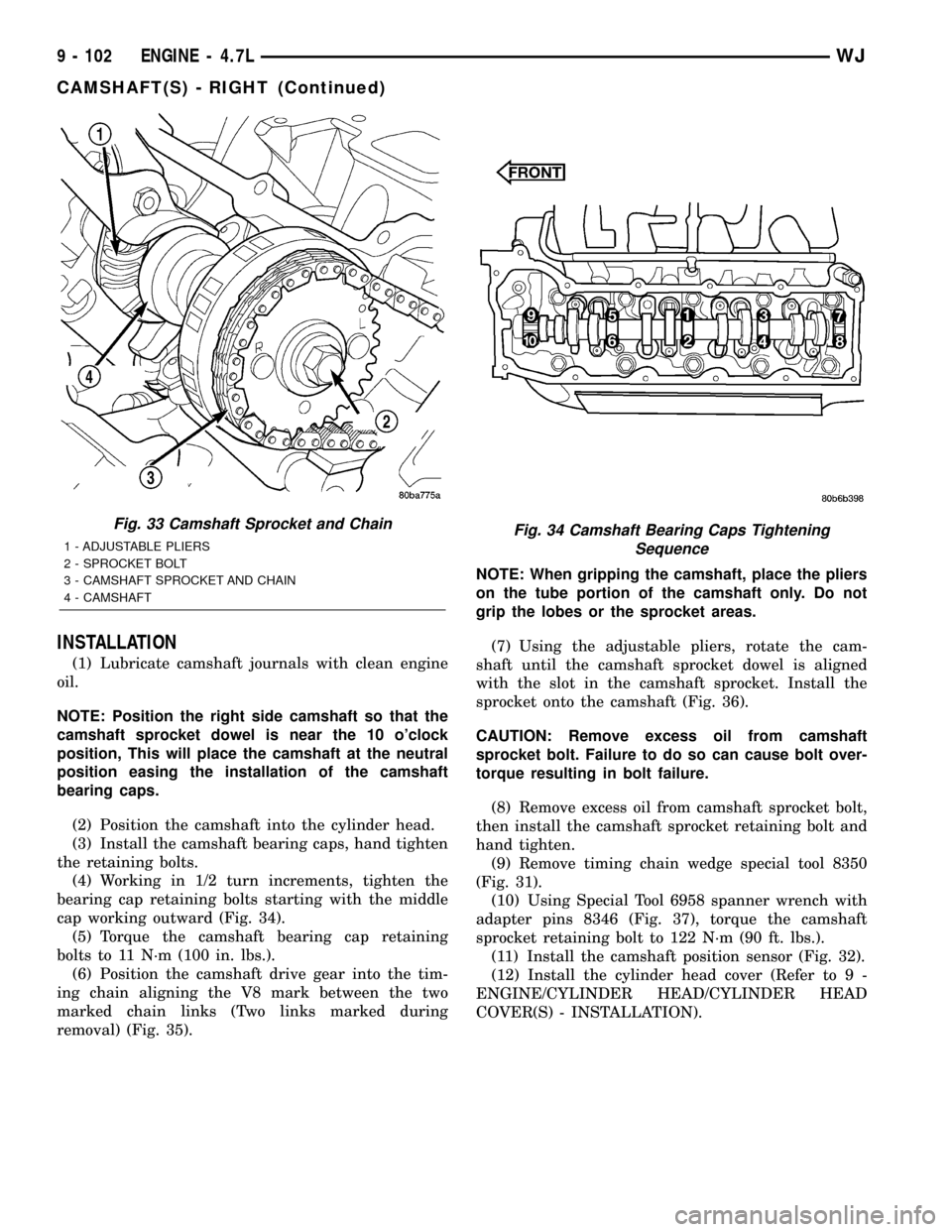
(4) Working in 1/2 turn increments, tighten the
bearing cap retaining bolts starting with the middle
cap working outward (Fig. 34).
(5) Torque the camshaft bearing cap retaining
bolts to 11 N´m (100 in. lbs.).
(6) Position the camshaft drive gear into the tim-
ing chain aligning the V8 mark between the two
marked chain links (Two links marked during
removal) (Fig. 35).NOTE: When gripping the camshaft, place the pliers
on the tube portion of the camshaft only. Do not
grip the lobes or the sprocket areas.
(7) Using the adjustable pliers, rotate the cam-
shaft until the camshaft sprocket dowel is aligned
with the slot in the camshaft sprocket. Install the
sprocket onto the camshaft (Fig. 36).
CAUTION: Remove excess oil from camshaft
sprocket bolt. Failure to do so can cause bolt over-
torque resulting in bolt failure.
(8) Remove excess oil from camshaft sprocket bolt,
then install the camshaft sprocket retaining bolt and
hand tighten.
(9) Remove timing chain wedge special tool 8350
(Fig. 31).
(10) Using Special Tool 6958 spanner wrench with
adapter pins 8346 (Fig. 37), torque the camshaft
sprocket retaining bolt to 122 N´m (90 ft. lbs.).
(11) Install the camshaft position sensor (Fig. 32).
(12) Install the cylinder head cover (Refer to 9 -
ENGINE/CYLINDER HEAD/CYLINDER HEAD
COVER(S) - INSTALLATION).
Fig. 33 Camshaft Sprocket and Chain
1 - ADJUSTABLE PLIERS
2 - SPROCKET BOLT
3 - CAMSHAFT SPROCKET AND CHAIN
4 - CAMSHAFTFig. 34 Camshaft Bearing Caps Tightening
Sequence
9 - 102 ENGINE - 4.7LWJ
CAMSHAFT(S) - RIGHT (Continued)
Page 1385 of 2199
NOTE: The blue link plates on the chains and the
dots on the camshaft drive sprockets may not line
up during the timing verification procedure. The
blue link plates are lined up with the sprocket dots
only when re-timing the complete timing drive.
Once the timing drive is rotated blue link-to-dot
alignment is no longer valid.
Engine base timing can be verified by the following
procedure:
(1) Remove the cylinder head covers (Refer to 9 -
ENGINE/CYLINDER HEAD/CYLINDER HEAD
COVER(S) - REMOVAL).
(2) Using a mirror, locate the TDC arrow on the
front cover (Fig. 110). Rotate the crankshaft until the
mark on the crankshaft damper is aligned with the
TDC arrow on the front cover. The engine is now at
TDC.(3) Note the location of the V8 mark stamped into
the camshaft drive gears (Fig. 111). If the V8 mark
on each camshaft drive gear is at the twelve o'clock
position, the engine is at TDC (cylinder #1) on the
exhaust stroke. If the V8 mark on each gear is at the
six o'clock position, the engine is at TDC (cylinder
#1) on the compression stroke.
(4) If both of the camshaft drive gears are off in
the same or opposite directions, the primary chain or
both secondary chains are at fault. Refer to Timing
Chain and Sprockets procedure in this section.
(5) If only one of the camshaft drive gears is off
and the other is correct, the problem is confined to
one secondary chain. Refer to Single camshaft tim-
ing, in this procedure.
(6) If both camshaft drive gear V8 marks are at
the twelve o'clock or the six o' clock position the
engine base timing is correct. Reinstall the cylinder
head covers.
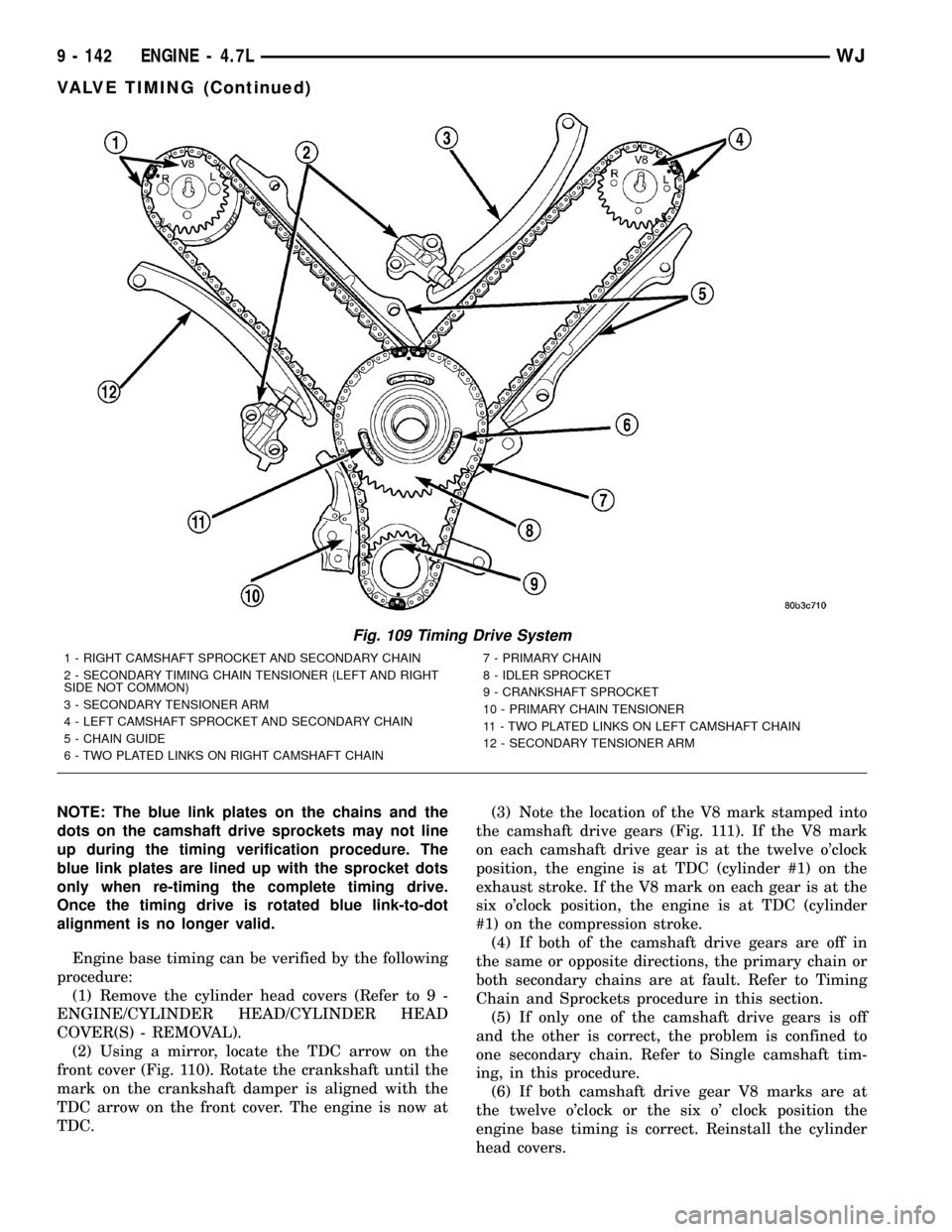
Fig. 109 Timing Drive System
1 - RIGHT CAMSHAFT SPROCKET AND SECONDARY CHAIN
2 - SECONDARY TIMING CHAIN TENSIONER (LEFT AND RIGHT
SIDE NOT COMMON)
3 - SECONDARY TENSIONER ARM
4 - LEFT CAMSHAFT SPROCKET AND SECONDARY CHAIN
5 - CHAIN GUIDE
6 - TWO PLATED LINKS ON RIGHT CAMSHAFT CHAIN7 - PRIMARY CHAIN
8 - IDLER SPROCKET
9 - CRANKSHAFT SPROCKET
10 - PRIMARY CHAIN TENSIONER
11 - TWO PLATED LINKS ON LEFT CAMSHAFT CHAIN
12 - SECONDARY TENSIONER ARM
9 - 142 ENGINE - 4.7LWJ
VALVE TIMING (Continued)
Page 1386 of 2199
SINGLE CAMSHAFT TIMING
NOTE: to adjust the timing on one camshaft, pre-
form the following procedure.
(1) Using Chain Tensioner Wedge, special tool
8350, stabilize the secondary chain drive (Fig. 112).
For reference purposes, mark the chain-to-sprocket
position (Fig. 112).
(2) Remove the camshaft drive gear retaining bolt.
(3) Carefully remove the camshaft drive gear from
the camshaft.
(4) Re-index the camshaft drive gear in the chain
until the V8 mark is at the same position as the V8
mark on the opposite camshaft drive gear.
NOTE: When gripping the camshaft, place the pliers
on the tube portion of the camshaft only. Do not
grip the lobes or the sprocket areas.
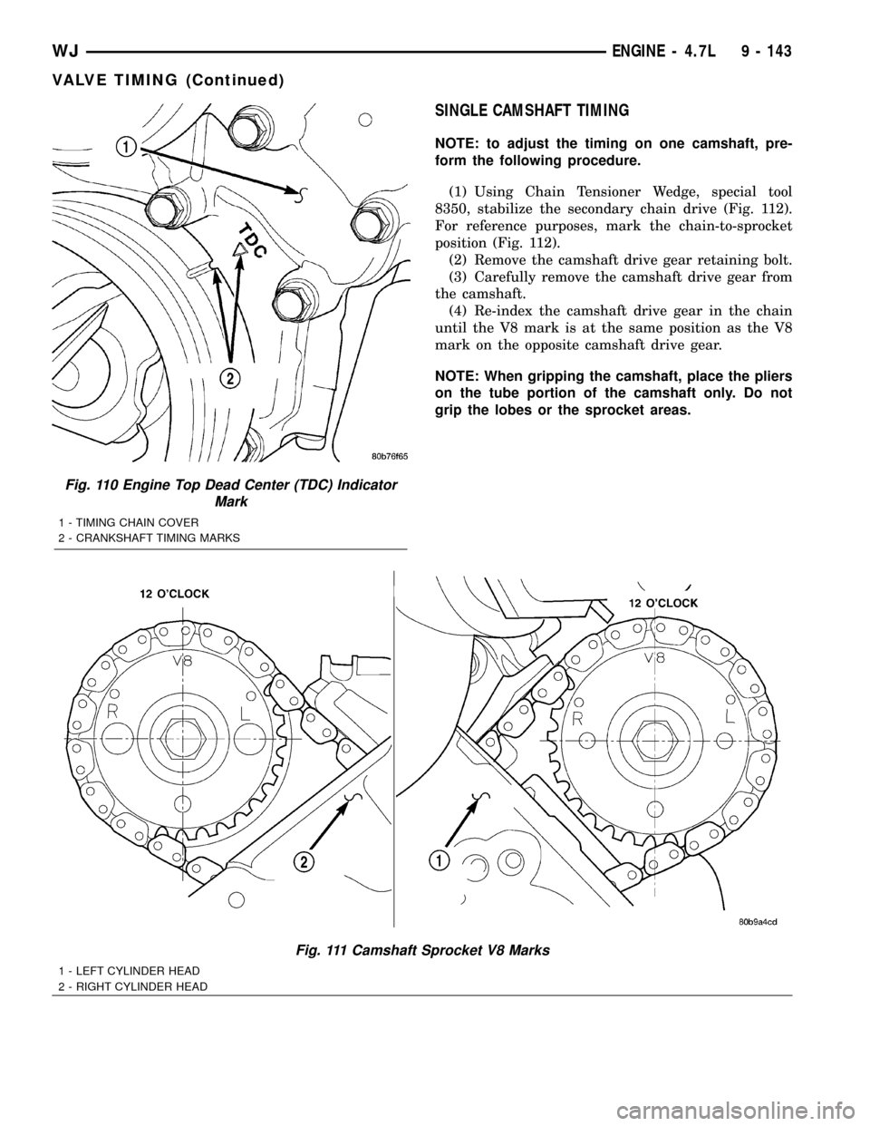
Fig. 110 Engine Top Dead Center (TDC) Indicator
Mark
1 - TIMING CHAIN COVER
2 - CRANKSHAFT TIMING MARKS
Fig. 111 Camshaft Sprocket V8 Marks
1 - LEFT CYLINDER HEAD
2 - RIGHT CYLINDER HEAD
WJENGINE - 4.7L 9 - 143
VALVE TIMING (Continued)
Page 1387 of 2199
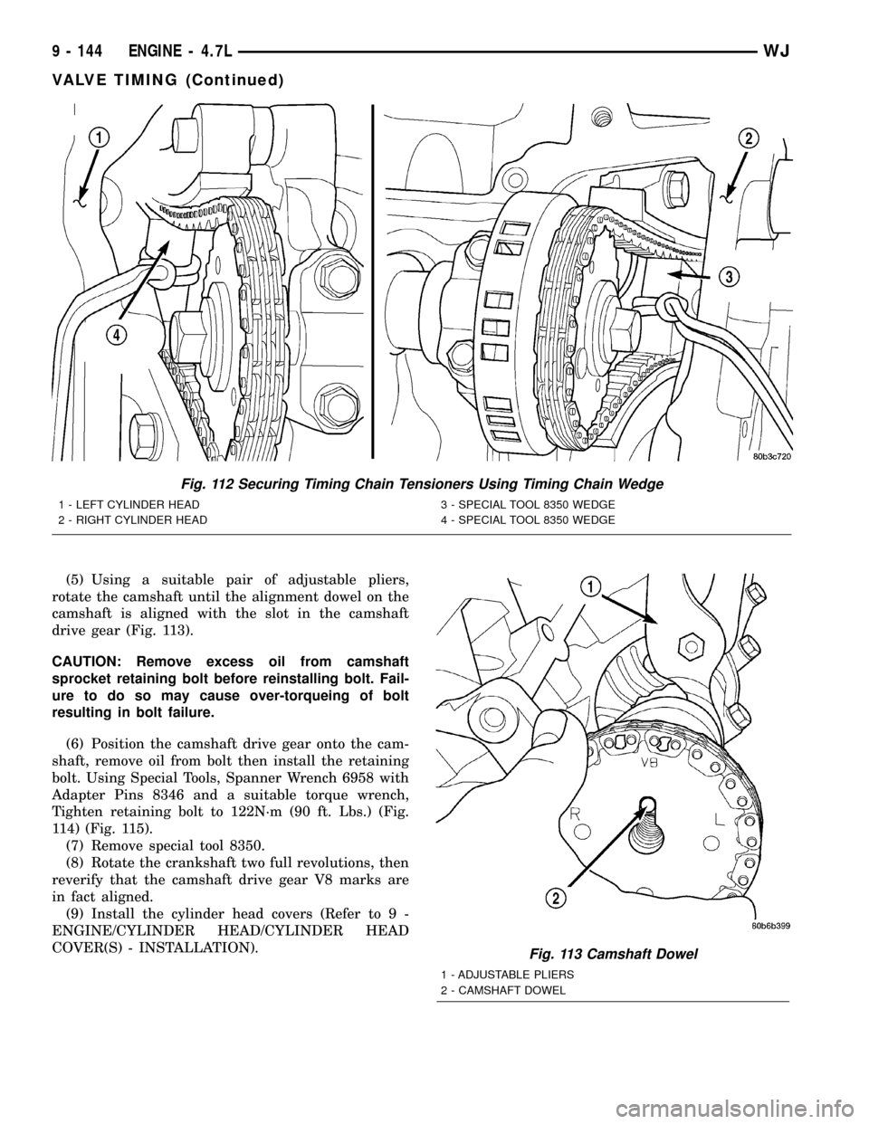
(5) Using a suitable pair of adjustable pliers,
rotate the camshaft until the alignment dowel on the
camshaft is aligned with the slot in the camshaft
drive gear (Fig. 113).
CAUTION: Remove excess oil from camshaft
sprocket retaining bolt before reinstalling bolt. Fail-
ure to do so may cause over-torqueing of bolt
resulting in bolt failure.
(6) Position the camshaft drive gear onto the cam-
shaft, remove oil from bolt then install the retaining
bolt. Using Special Tools, Spanner Wrench 6958 with
Adapter Pins 8346 and a suitable torque wrench,
Tighten retaining bolt to 122N´m (90 ft. Lbs.) (Fig.
114) (Fig. 115).
(7) Remove special tool 8350.
(8) Rotate the crankshaft two full revolutions, then
reverify that the camshaft drive gear V8 marks are
in fact aligned.
(9) Install the cylinder head covers (Refer to 9 -
ENGINE/CYLINDER HEAD/CYLINDER HEAD
COVER(S) - INSTALLATION).
Fig. 112 Securing Timing Chain Tensioners Using Timing Chain Wedge
1 - LEFT CYLINDER HEAD
2 - RIGHT CYLINDER HEAD3 - SPECIAL TOOL 8350 WEDGE
4 - SPECIAL TOOL 8350 WEDGE
Fig. 113 Camshaft Dowel
1 - ADJUSTABLE PLIERS
2 - CAMSHAFT DOWEL
9 - 144 ENGINE - 4.7LWJ
VALVE TIMING (Continued)
Page 1394 of 2199
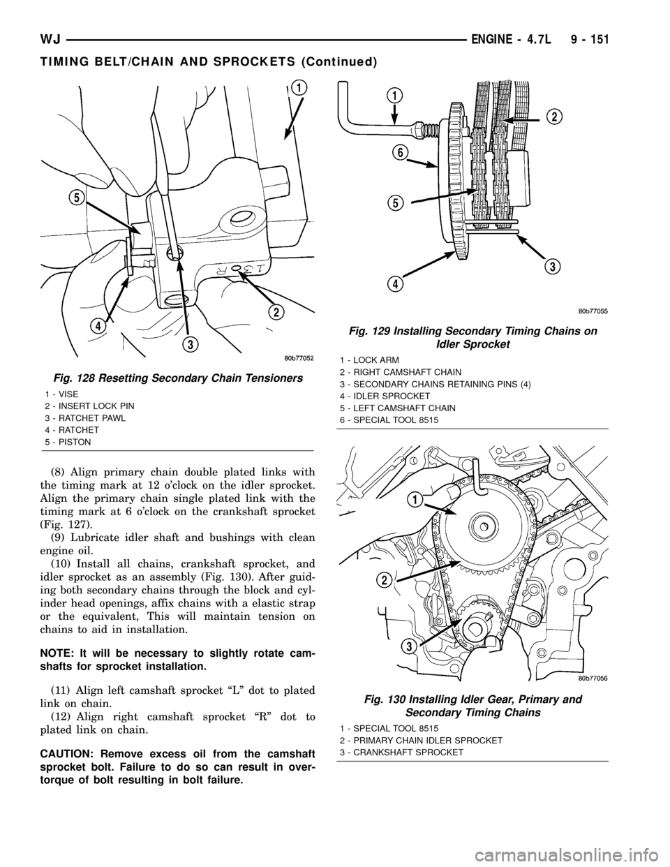
(8) Align primary chain double plated links with
the timing mark at 12 o'clock on the idler sprocket.
Align the primary chain single plated link with the
timing mark at 6 o'clock on the crankshaft sprocket
(Fig. 127).
(9) Lubricate idler shaft and bushings with clean
engine oil.
(10) Install all chains, crankshaft sprocket, and
idler sprocket as an assembly (Fig. 130). After guid-
ing both secondary chains through the block and cyl-
inder head openings, affix chains with a elastic strap
or the equivalent, This will maintain tension on
chains to aid in installation.
NOTE: It will be necessary to slightly rotate cam-
shafts for sprocket installation.
(11) Align left camshaft sprocket ªLº dot to plated
link on chain.
(12) Align right camshaft sprocket ªRº dot to
plated link on chain.
CAUTION: Remove excess oil from the camshaft
sprocket bolt. Failure to do so can result in over-
torque of bolt resulting in bolt failure.
Fig. 128 Resetting Secondary Chain Tensioners
1 - VISE
2 - INSERT LOCK PIN
3 - RATCHET PAWL
4 - RATCHET
5 - PISTON
Fig. 129 Installing Secondary Timing Chains on
Idler Sprocket
1 - LOCK ARM
2 - RIGHT CAMSHAFT CHAIN
3 - SECONDARY CHAINS RETAINING PINS (4)
4 - IDLER SPROCKET
5 - LEFT CAMSHAFT CHAIN
6 - SPECIAL TOOL 8515
Fig. 130 Installing Idler Gear, Primary and
Secondary Timing Chains
1 - SPECIAL TOOL 8515
2 - PRIMARY CHAIN IDLER SPROCKET
3 - CRANKSHAFT SPROCKET
WJENGINE - 4.7L 9 - 151
TIMING BELT/CHAIN AND SPROCKETS (Continued)
Page 1395 of 2199
(13) Remove Special Tool 8515, then attach both
sprockets to camshafts. Remove excess oil from bolts,
then Install sprocket bolts, but do not tighten at this
time.
(14) Verify that all plated links are aligned with
the marks on all sprockets and the ªV8º marks on
camshaft sprockets are at the 12 o'clock position (Fig.
127).
CAUTION: Ensure the plate between the left sec-
ondary chain tensioner and block is correctly
installed.
(15) Install both secondary chain tensioners.
Tighten bolts to 28 N´m (250 in. lbs.).
NOTE: Left and right secondary chain tensioners
are not common.
(16) Before installing idler sprocket bolt, lubricate
washer with oil, and tighten idler sprocket assembly
retaining bolt to 34 N´m (25 ft. lbs.).
(17) Remove all locking pins (3) from tensioners.
CAUTION: After pulling locking pins out of each
tensioner, DO NOT manually extend the tensioner(s)
ratchet. Doing so will over tension the chains,
resulting in noise and/or high timing chain loads.
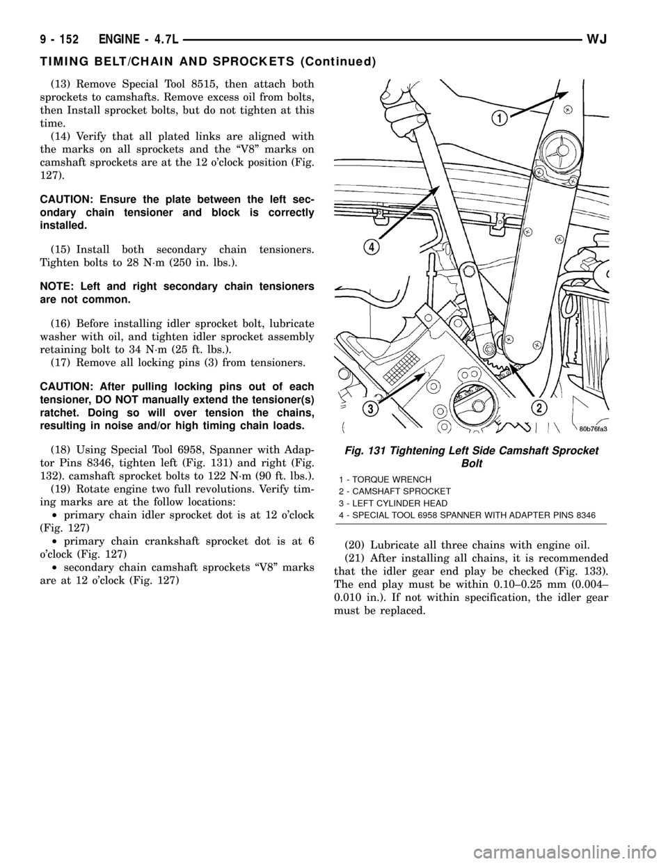
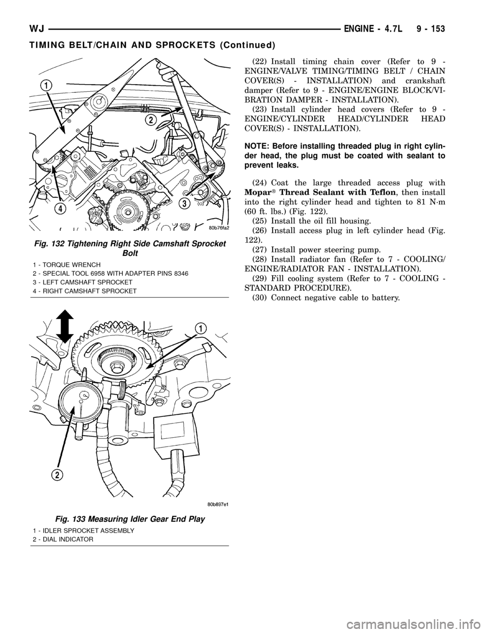
(18) Using Special Tool 6958, Spanner with Adap-
tor Pins 8346, tighten left (Fig. 131) and right (Fig.
132). camshaft sprocket bolts to 122 N´m (90 ft. lbs.).
(19) Rotate engine two full revolutions. Verify tim-
ing marks are at the follow locations:
²primary chain idler sprocket dot is at 12 o'clock
(Fig. 127)
²primary chain crankshaft sprocket dot is at 6
o'clock (Fig. 127)
²secondary chain camshaft sprockets ªV8º marks
are at 12 o'clock (Fig. 127)(20) Lubricate all three chains with engine oil.
(21) After installing all chains, it is recommended
that the idler gear end play be checked (Fig. 133).
The end play must be within 0.10±0.25 mm (0.004±
0.010 in.). If not within specification, the idler gear
must be replaced.
Fig. 131 Tightening Left Side Camshaft Sprocket
Bolt
1 - TORQUE WRENCH
2 - CAMSHAFT SPROCKET
3 - LEFT CYLINDER HEAD
4 - SPECIAL TOOL 6958 SPANNER WITH ADAPTER PINS 8346
9 - 152 ENGINE - 4.7LWJ
TIMING BELT/CHAIN AND SPROCKETS (Continued)
Page 1396 of 2199
(22) Install timing chain cover (Refer to 9 -
ENGINE/VALVE TIMING/TIMING BELT / CHAIN
COVER(S) - INSTALLATION) and crankshaft
damper (Refer to 9 - ENGINE/ENGINE BLOCK/VI-
BRATION DAMPER - INSTALLATION).
(23) Install cylinder head covers (Refer to 9 -
ENGINE/CYLINDER HEAD/CYLINDER HEAD
COVER(S) - INSTALLATION).
NOTE: Before installing threaded plug in right cylin-
der head, the plug must be coated with sealant to
prevent leaks.
(24) Coat the large threaded access plug with
MopartThread Sealant with Teflon, then install
into the right cylinder head and tighten to 81 N´m
(60 ft. lbs.) (Fig. 122).
(25) Install the oil fill housing.
(26) Install access plug in left cylinder head (Fig.
122).
(27) Install power steering pump.
(28) Install radiator fan (Refer to 7 - COOLING/
ENGINE/RADIATOR FAN - INSTALLATION).
(29) Fill cooling system (Refer to 7 - COOLING -
STANDARD PROCEDURE).
(30) Connect negative cable to battery.
Fig. 132 Tightening Right Side Camshaft Sprocket
Bolt
1 - TORQUE WRENCH
2 - SPECIAL TOOL 6958 WITH ADAPTER PINS 8346
3 - LEFT CAMSHAFT SPROCKET
4 - RIGHT CAMSHAFT SPROCKET
Fig. 133 Measuring Idler Gear End Play
1 - IDLER SPROCKET ASSEMBLY
2 - DIAL INDICATOR
WJENGINE - 4.7L 9 - 153
TIMING BELT/CHAIN AND SPROCKETS (Continued)
Page 1428 of 2199
OPERATION
Voltage to operate the electric pump is supplied
through the fuel pump relay.
Fuel is drawn in through a filter at the bottom of
the module and pushed through the electric motor
gearset to the pump outlet.
Check Valve Operation:The pump outlet con-
tains a one-way check valve to prevent fuel flow back
into the tank and to maintain fuel supply line pres-
sure (engine warm) when pump is not operational. It
is also used to keep the fuel supply line full of gaso-
line when pump is not operational. After the vehicle
has cooled down, fuel pressure may drop to 0 psi
(cold fluid contracts), but liquid gasoline will remain
in fuel supply line between the check valve and fuel
injectors.Fuel pressure that has dropped to 0
psi on a cooled down vehicle (engine off) is a
normal condition.Refer to the Fuel Pressure Leak
Down Test for more information.
The electric fuel pump is not a separate, service-
able component.
DIAGNOSIS AND TESTING
DIAGNOSIS AND TESTING - FUEL PUMP
CAPACITY TEST
Before performing this test, verify fuel pump
pressure. Refer to Fuel Pump Pressure Test.
Use this test in conjunction with the Fuel Pres-
sure Leak Down Test.
(1) Release fuel system pressure. Refer to Fuel
Pressure Release Procedure.
(2) Disconnect fuel supply line at fuel rail. Refer to
Quick-Connect Fittings. Some engines may require
air cleaner housing removal before line disconnection.
(3) Obtain correct Fuel Line Pressure Test Adapter
Tool Hose. Tool number 6539 is used for 5/16º fuel
lines and tool number 6631 is used for 3/8º fuel lines.
(4) Connect correct Fuel Line Pressure Test
Adapter Tool Hose into disconnected fuel supply line.
Insert other end of Adaptor Tool Hose into a gradu-
ated container.
(5) Remove fuel fill cap.
(6) To activate fuel pump and pressurize system,
obtain DRBtscan tool and actuate ASD Fuel System
Test.
(7) A good fuel pump will deliver at least 1/4 liter
of fuel in 7 seconds. Do not operate fuel pump for
longer than 7 seconds with fuel line disconnected as
fuel pump module reservoir may run empty.
(a) If capacity is lower than specification, but
fuel pump can be heard operating through fuel fill
cap opening, check for a kinked/damaged fuel sup-
ply line somewhere between fuel rail and fuel
pump module.(b) If line is not kinked/damaged, and fuel pres-
sure is OK, but capacity is low, replace fuel filter/
fuel pressure regulator. The filter/regulator may be
serviced separately on certain applications. Refer
to Fuel Filter/Fuel Pressure Regulator Removal/In-
stallation for additional information.
(c) If both fuel pressure and capacity are low,
replace fuel pump module assembly. Refer to Fuel
Pump Module Removal/Installation.
DIAGNOSIS AND TESTING - FUEL PUMP
AMPERAGE TEST
This amperage (current draw) test is to be done in
conjunction with the Fuel Pump Pressure Test, Fuel
Pump Capacity Test and Fuel Pressure Leak Down
Test. Before performing the amperage test, be sure
the temperature of the fuel tank is above 50É F (10É
C).
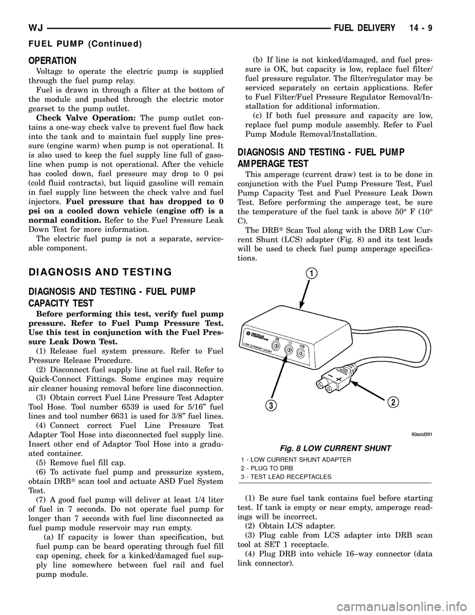
The DRBtScan Tool along with the DRB Low Cur-
rent Shunt (LCS) adapter (Fig. 8) and its test leads
will be used to check fuel pump amperage specifica-
tions.
(1) Be sure fuel tank contains fuel before starting
test. If tank is empty or near empty, amperage read-
ings will be incorrect.
(2) Obtain LCS adapter.
(3) Plug cable from LCS adapter into DRB scan
tool at SET 1 receptacle.
(4) Plug DRB into vehicle 16±way connector (data
link connector).
Fig. 8 LOW CURRENT SHUNT
1 - LOW CURRENT SHUNT ADAPTER
2 - PLUG TO DRB
3 - TEST LEAD RECEPTACLES
WJFUEL DELIVERY 14 - 9
FUEL PUMP (Continued)
Page 1478 of 2199
STEERING
TABLE OF CONTENTS
page page
STEERING
DESCRIPTION - POWER STEERING SYSTEM . . 1
OPERATION - POWER STEERING SYSTEM . . . 1
DIAGNOSIS AND TESTING
DIAGNOSIS AND TESTING - POWER
STEERING SYSTEM....................2
DIAGNOSIS AND TESTING - STEERING
FLOW AND PRESSURE.................4DIAGNOSIS AND TESTING - 4.7L -
HYDRAULIC..........................5
COLUMN...............................7
GEAR.................................16
LINKAGE..............................26
PUMP.................................31
STEERING
DESCRIPTION - POWER STEERING SYSTEM
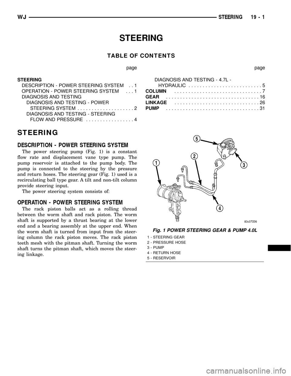
The power steering pump (Fig. 1) is a constant
flow rate and displacement vane type pump. The
pump reservoir is attached to the pump body. The
pump is connected to the steering by the pressure
and return hoses. The steering gear (Fig. 1) used is a
recirculating ball type gear. A tilt and non-tilt column
provide steering input.
The power steering system consists of:
OPERATION - POWER STEERING SYSTEM
The rack piston balls act as a rolling thread
between the worm shaft and rack piston. The worm
shaft is supported by a thrust bearing at the lower
end and a bearing assembly at the upper end. When
the worm shaft is turned from input from the steer-
ing column the rack piston moves. The rack piston
teeth mesh with the pitman shaft. Turning the worm
shaft turns the pitman shaft, which moves the steer-
ing linkage.
Fig. 1 POWER STEERING GEAR & PUMP 4.0L
1 - STEERING GEAR
2 - PRESSURE HOSE
3 - PUMP
4 - RETURN HOSE
5 - RESERVOIR
WJSTEERING 19 - 1