Starting systems JEEP GRAND CHEROKEE 2002 WJ / 2.G User Guide
[x] Cancel search | Manufacturer: JEEP, Model Year: 2002, Model line: GRAND CHEROKEE, Model: JEEP GRAND CHEROKEE 2002 WJ / 2.GPages: 2199, PDF Size: 76.01 MB
Page 661 of 2199

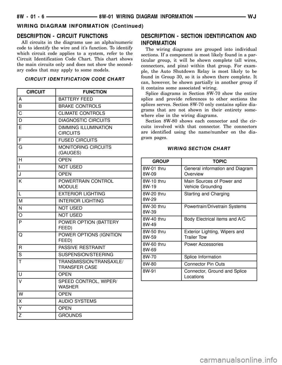
DESCRIPTION - CIRCUIT FUNCTIONS
All circuits in the diagrams use an alpha/numeric
code to identify the wire and it's function. To identify
which circuit code applies to a system, refer to the
Circuit Identification Code Chart. This chart shows
the main circuits only and does not show the second-
ary codes that may apply to some models.
CIRCUIT IDENTIFICATION CODE CHART
CIRCUIT FUNCTION
A BATTERY FEED
B BRAKE CONTROLS
C CLIMATE CONTROLS
D DIAGNOSTIC CIRCUITS
E DIMMING ILLUMINATION
CIRCUITS
F FUSED CIRCUITS
G MONITORING CIRCUITS
(GAUGES)
H OPEN
I NOT USED
J OPEN
K POWERTRAIN CONTROL
MODULE
L EXTERIOR LIGHTING
M INTERIOR LIGHTING
N NOT USED
O NOT USED
P POWER OPTION (BATTERY
FEED)
Q POWER OPTIONS (IGNITION
FEED)
R PASSIVE RESTRAINT
S SUSPENSION/STEERING
T TRANSMISSION/TRANSAXLE/
TRANSFER CASE
U OPEN
V SPEED CONTROL, WIPER/
WASHER
W OPEN
X AUDIO SYSTEMS
Y OPEN
Z GROUNDS
DESCRIPTION - SECTION IDENTIFICATION AND
INFORMATION
The wiring diagrams are grouped into individual
sections. If a component is most likely found in a par-
ticular group, it will be shown complete (all wires,
connectors, and pins) within that group. For exam-
ple, the Auto Shutdown Relay is most likely to be
found in Group 30, so it is shown there complete. It
can, however, be shown partially in another group if
it contains some associated wiring.
Splice diagrams in Section 8W-70 show the entire
splice and provide references to other sections the
splices serves. Section 8W-70 only contains splice dia-
grams that are not shown in their entirety some-
where else in the wiring diagrams.
Section 8W-80 shows each connector and the cir-
cuits involved with that connector. The connectors
are identified using the name/number on the dia-
gram pages.
WIRING SECTION CHART
GROUP TOPIC
8W-01 thru
8W-09General information and Diagram
Overview
8W-10 thru
8W-19Main Sources of Power and
Vehicle Grounding
8W-20 thru
8W-29Starting and Charging
8W-30 thru
8W-39Powertrain/Drivetrain Systems
8W-40 thru
8W-49Body Electrical items and A/C
8W-50 thru
8W-59Exterior Lighting, Wipers and
Trailer Tow
8W-60 thru
8W-69Power Accessories
8W-70 Splice Information
8W-80 Connector Pin Outs
8W-91 Connector, Ground and Splice
Locations
8W - 01 - 6 8W-01 WIRING DIAGRAM INFORMATIONWJ
WIRING DIAGRAM INFORMATION (Continued)
Page 669 of 2199

DIODE
REMOVAL
(1) Disconnect the battery.
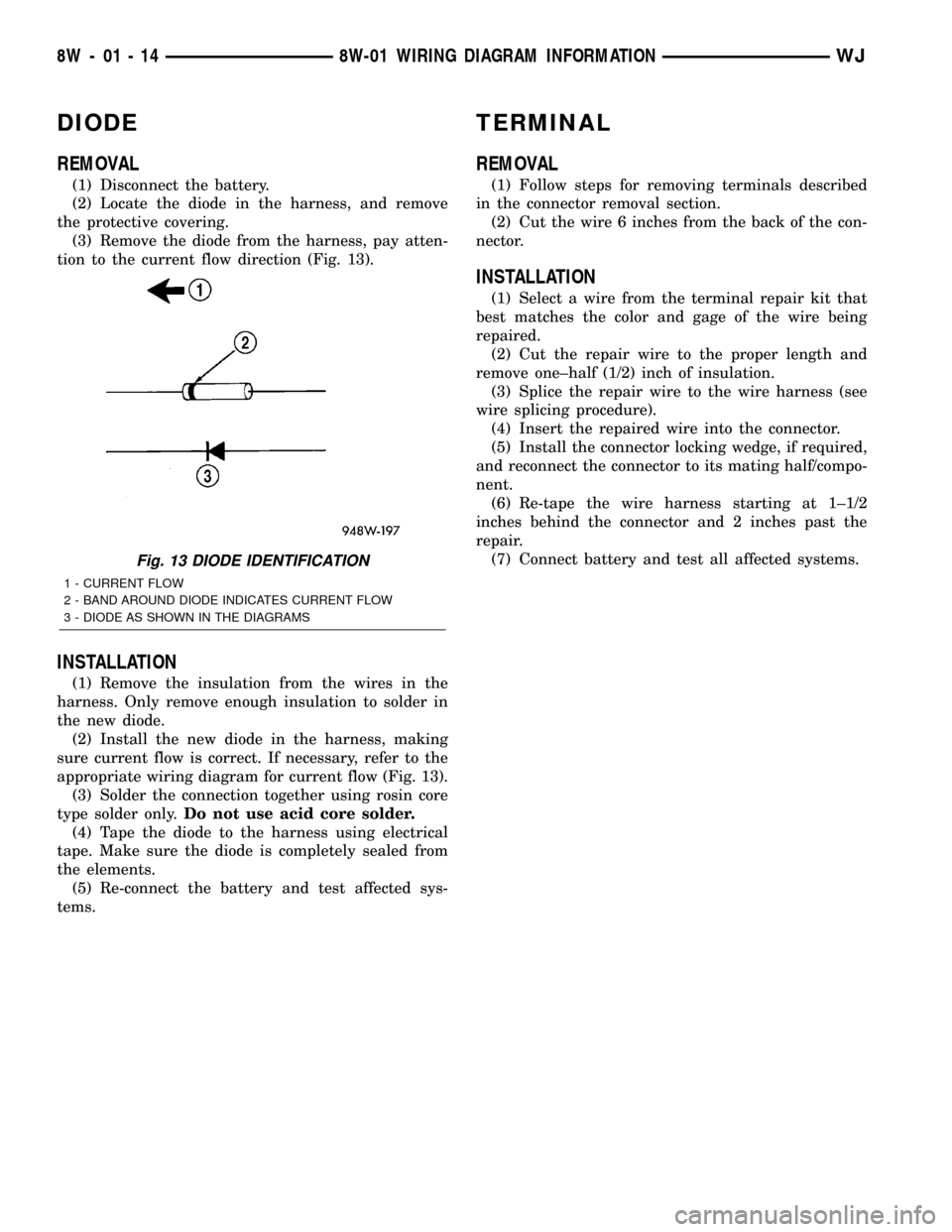
(2) Locate the diode in the harness, and remove
the protective covering.
(3) Remove the diode from the harness, pay atten-
tion to the current flow direction (Fig. 13).
INSTALLATION
(1) Remove the insulation from the wires in the
harness. Only remove enough insulation to solder in
the new diode.
(2) Install the new diode in the harness, making
sure current flow is correct. If necessary, refer to the
appropriate wiring diagram for current flow (Fig. 13).
(3) Solder the connection together using rosin core
type solder only.Do not use acid core solder.
(4) Tape the diode to the harness using electrical
tape. Make sure the diode is completely sealed from
the elements.
(5) Re-connect the battery and test affected sys-
tems.
TERMINAL
REMOVAL
(1) Follow steps for removing terminals described
in the connector removal section.
(2) Cut the wire 6 inches from the back of the con-
nector.
INSTALLATION
(1) Select a wire from the terminal repair kit that
best matches the color and gage of the wire being
repaired.
(2) Cut the repair wire to the proper length and
remove one±half (1/2) inch of insulation.
(3) Splice the repair wire to the wire harness (see
wire splicing procedure).
(4) Insert the repaired wire into the connector.
(5) Install the connector locking wedge, if required,
and reconnect the connector to its mating half/compo-
nent.
(6) Re-tape the wire harness starting at 1±1/2
inches behind the connector and 2 inches past the
repair.
(7) Connect battery and test all affected systems.
Fig. 13 DIODE IDENTIFICATION
1 - CURRENT FLOW
2 - BAND AROUND DIODE INDICATES CURRENT FLOW
3 - DIODE AS SHOWN IN THE DIAGRAMS
8W - 01 - 14 8W-01 WIRING DIAGRAM INFORMATIONWJ
Page 1384 of 2199

INSPECTION
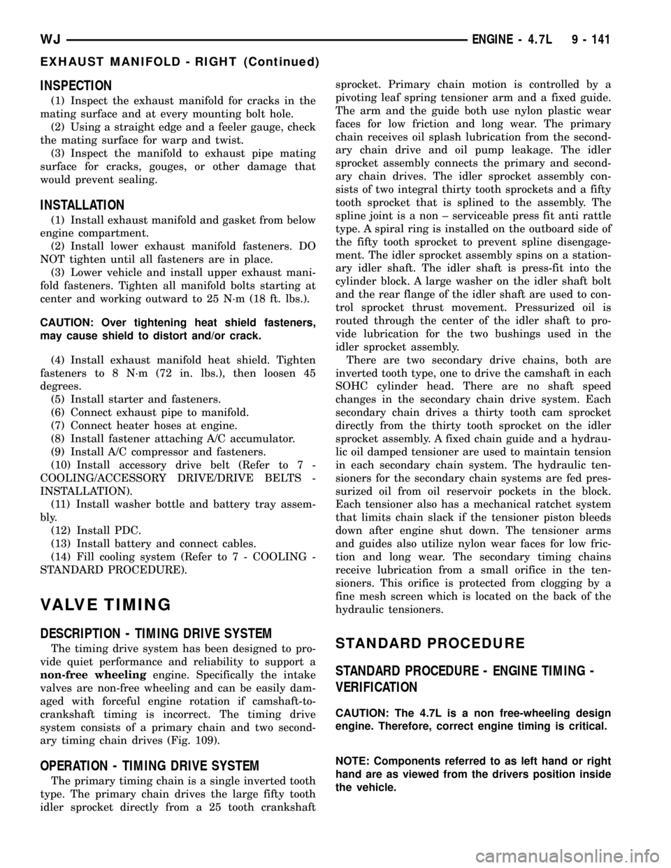
(1) Inspect the exhaust manifold for cracks in the
mating surface and at every mounting bolt hole.
(2) Using a straight edge and a feeler gauge, check
the mating surface for warp and twist.
(3) Inspect the manifold to exhaust pipe mating
surface for cracks, gouges, or other damage that
would prevent sealing.
INSTALLATION
(1) Install exhaust manifold and gasket from below
engine compartment.
(2) Install lower exhaust manifold fasteners. DO
NOT tighten until all fasteners are in place.
(3) Lower vehicle and install upper exhaust mani-
fold fasteners. Tighten all manifold bolts starting at
center and working outward to 25 N´m (18 ft. lbs.).
CAUTION: Over tightening heat shield fasteners,
may cause shield to distort and/or crack.
(4) Install exhaust manifold heat shield. Tighten
fasteners to 8 N´m (72 in. lbs.), then loosen 45
degrees.
(5) Install starter and fasteners.
(6) Connect exhaust pipe to manifold.
(7) Connect heater hoses at engine.
(8) Install fastener attaching A/C accumulator.
(9) Install A/C compressor and fasteners.
(10) Install accessory drive belt (Refer to 7 -
COOLING/ACCESSORY DRIVE/DRIVE BELTS -
INSTALLATION).
(11) Install washer bottle and battery tray assem-
bly.
(12) Install PDC.
(13) Install battery and connect cables.
(14) Fill cooling system (Refer to 7 - COOLING -
STANDARD PROCEDURE).
VALVE TIMING
DESCRIPTION - TIMING DRIVE SYSTEM
The timing drive system has been designed to pro-
vide quiet performance and reliability to support a
non-free wheelingengine. Specifically the intake
valves are non-free wheeling and can be easily dam-
aged with forceful engine rotation if camshaft-to-
crankshaft timing is incorrect. The timing drive
system consists of a primary chain and two second-
ary timing chain drives (Fig. 109).
OPERATION - TIMING DRIVE SYSTEM
The primary timing chain is a single inverted tooth
type. The primary chain drives the large fifty tooth
idler sprocket directly from a 25 tooth crankshaftsprocket. Primary chain motion is controlled by a
pivoting leaf spring tensioner arm and a fixed guide.
The arm and the guide both use nylon plastic wear
faces for low friction and long wear. The primary
chain receives oil splash lubrication from the second-
ary chain drive and oil pump leakage. The idler
sprocket assembly connects the primary and second-
ary chain drives. The idler sprocket assembly con-
sists of two integral thirty tooth sprockets and a fifty
tooth sprocket that is splined to the assembly. The
spline joint is a non ± serviceable press fit anti rattle
type. A spiral ring is installed on the outboard side of
the fifty tooth sprocket to prevent spline disengage-
ment. The idler sprocket assembly spins on a station-
ary idler shaft. The idler shaft is press-fit into the
cylinder block. A large washer on the idler shaft bolt
and the rear flange of the idler shaft are used to con-
trol sprocket thrust movement. Pressurized oil is
routed through the center of the idler shaft to pro-
vide lubrication for the two bushings used in the
idler sprocket assembly.
There are two secondary drive chains, both are
inverted tooth type, one to drive the camshaft in each
SOHC cylinder head. There are no shaft speed
changes in the secondary chain drive system. Each
secondary chain drives a thirty tooth cam sprocket
directly from the thirty tooth sprocket on the idler
sprocket assembly. A fixed chain guide and a hydrau-
lic oil damped tensioner are used to maintain tension
in each secondary chain system. The hydraulic ten-
sioners for the secondary chain systems are fed pres-
surized oil from oil reservoir pockets in the block.
Each tensioner also has a mechanical ratchet system
that limits chain slack if the tensioner piston bleeds
down after engine shut down. The tensioner arms
and guides also utilize nylon wear faces for low fric-
tion and long wear. The secondary timing chains
receive lubrication from a small orifice in the ten-
sioners. This orifice is protected from clogging by a
fine mesh screen which is located on the back of the
hydraulic tensioners.
STANDARD PROCEDURE
STANDARD PROCEDURE - ENGINE TIMING -
VERIFICATION
CAUTION: The 4.7L is a non free-wheeling design
engine. Therefore, correct engine timing is critical.
NOTE: Components referred to as left hand or right
hand are as viewed from the drivers position inside
the vehicle.
WJENGINE - 4.7L 9 - 141
EXHAUST MANIFOLD - RIGHT (Continued)