ad blue JEEP GRAND CHEROKEE 2002 WJ / 2.G User Guide
[x] Cancel search | Manufacturer: JEEP, Model Year: 2002, Model line: GRAND CHEROKEE, Model: JEEP GRAND CHEROKEE 2002 WJ / 2.GPages: 2199, PDF Size: 76.01 MB
Page 449 of 2199

WARNING: ON VEHICLES EQUIPPED WITH AIR-
BAGS, DISABLE THE SUPPLEMENTAL RESTRAINT
SYSTEM BEFORE ATTEMPTING ANY STEERING
WHEEL, STEERING COLUMN, DRIVER AIRBAG,
PASSENGER AIRBAG, SIDE CURTAIN AIRBAG,
FRONT IMPACT SENSOR, SIDE IMPACT SENSOR,
OR INSTRUMENT PANEL COMPONENT DIAGNOSIS
OR SERVICE. DISCONNECT AND ISOLATE THE
BATTERY NEGATIVE (GROUND) CABLE, THEN
WAIT TWO MINUTES FOR THE SYSTEM CAPACI-
TOR TO DISCHARGE BEFORE PERFORMING FUR-
THER DIAGNOSIS OR SERVICE. THIS IS THE ONLY
SURE WAY TO DISABLE THE SUPPLEMENTAL
RESTRAINT SYSTEM. FAILURE TO TAKE THE
PROPER PRECAUTIONS COULD RESULT IN ACCI-
DENTAL AIRBAG DEPLOYMENT AND POSSIBLE
PERSONAL INJURY.
(1) Disconnect and isolate the battery negative
cable. Remove the instrument cluster from the
instrument panel and disconnect the instrument
panel wire harness for the instrument cluster from
the cluster connector receptacle.
(2) Reconnect the battery negative cable. Activate
the hazard warning system by moving the hazard
warning switch button to the On position. Check for
battery voltage at the inoperative (right or left) turn
signal circuit cavity of the instrument panel wire
harness connector for the instrument cluster. There
should be a switching (on and off) battery voltage sig-
nal present. If OK, replace the faulty (right or left)
turn signal indicator bulb. If not OK, repair the open
(right or left) turn signal circuit between the instru-
ment cluster and the combination flasher in the
Junction Block (JB) as required.
VOLTAGE GAUGE
DESCRIPTION
A voltage gauge is standard equipment on all
instrument clusters. The voltage gauge is located in
the upper left corner of the instrument cluster, to the
left of the tachometer. The voltage gauge consists of a
movable gauge needle or pointer controlled by the
instrument cluster circuitry and a fixed 90 degree
scale on the gauge dial face that reads left-to-right
from 9 volts to 19 volts. An International Control and
Display Symbol icon for ªBattery Charging Condi-
tionº is located on the gauge dial face.
The voltage gauge graphics are either white, gray
and orange against a black gauge dial face (base
cluster) or black, gray and red against a taupe gauge
dial face (premium cluster), making them clearly vis-
ible within the instrument cluster in daylight. When
illuminated from behind by the panel lamps dimmer
controlled cluster illumination lighting with the exte-rior lamps turned On, the base cluster white gauge
graphics appear blue-green and the orange graphics
still appear orange, while the premium cluster taupe
gauge dial face appears blue-green with the black
graphics silhouetted against the illuminated back-
ground and the red graphics still appear red. The
gray gauge graphics for both versions of the cluster
are not illuminated. The orange gauge needle in the
base cluster gauge is internally illuminated, while
the black gauge needle in the premium cluster gauge
is not.
Base cluster gauge illumination is provided by
replaceable incandescent bulb and bulb holder units
located on the instrument cluster electronic circuit
board. Premium cluster gauge illumination is pro-
vided by an integral electro-luminescent lamp that is
serviced as a unit with the instrument cluster. The
voltage gauge is serviced as a unit with the instru-
ment cluster.
OPERATION
The voltage gauge gives an indication to the vehi-
cle operator of the electrical system voltage. This
gauge is controlled by the instrument cluster circuit
board based upon cluster programming and elec-
tronic messages received by the cluster from the
Powertrain Control Module (PCM) over the Program-
mable Communications Interface (PCI) data bus. The
voltage gauge is an air core magnetic unit that
receives battery current on the instrument cluster
electronic circuit board through the fused ignition
switch output (run-start) circuit whenever the igni-
tion switch is in the On or Start positions. The clus-
ter is programmed to move the gauge needle back to
the low end of the scale after the ignition switch is
turned to the Off position. The instrument cluster
circuitry controls the gauge needle position and pro-
vides the following features:
²System Voltage Message- Each time the clus-
ter receives a message from the PCM indicating the
system voltage, the cluster moves the gauge needle to
the relative voltage level position on the gauge scale.
²System Voltage Low Message- Each time the
cluster receives a message from the PCM indicating
the system voltage is low (system voltage is about
eleven volts or lower), the gauge needle is moved to
the relative voltage position in the red zone of the
gauge scale and the check gauges indicator is illumi-
nated. The gauge needle remains in the red zone and
the check gauges indicator remains illuminated until
the cluster receives a message from the PCM indicat-
ing there is no low system voltage condition (system
voltage is above about eleven volts, but lower than
about sixteen volts).
²System Voltage High Message- Each time
the cluster receives a message from the PCM indicat-
8J - 34 INSTRUMENT CLUSTERWJ
TURN SIGNAL INDICATOR (Continued)
Page 660 of 2199
TERMINOLOGY
This is a list of terms and definitions used in the
wiring diagrams.
LHD .................Left Hand Drive Vehicles
RHD................Right Hand Drive Vehicles
ATX . . Automatic Transmissions-Front Wheel Drive
MTX....Manual Transmissions-Front Wheel Drive
AT ....Automatic Transmissions-Rear Wheel Drive
MT .....Manual Transmissions-Rear Wheel Drive
SOHC...........Single Over Head Cam Engine
DOHC..........Double Over Head Cam Engine
Built-Up-Export........ Vehicles Built For Sale In
Markets Other Than North America
Except Built-Up-Export . . Vehicles Built For Sale In
North America
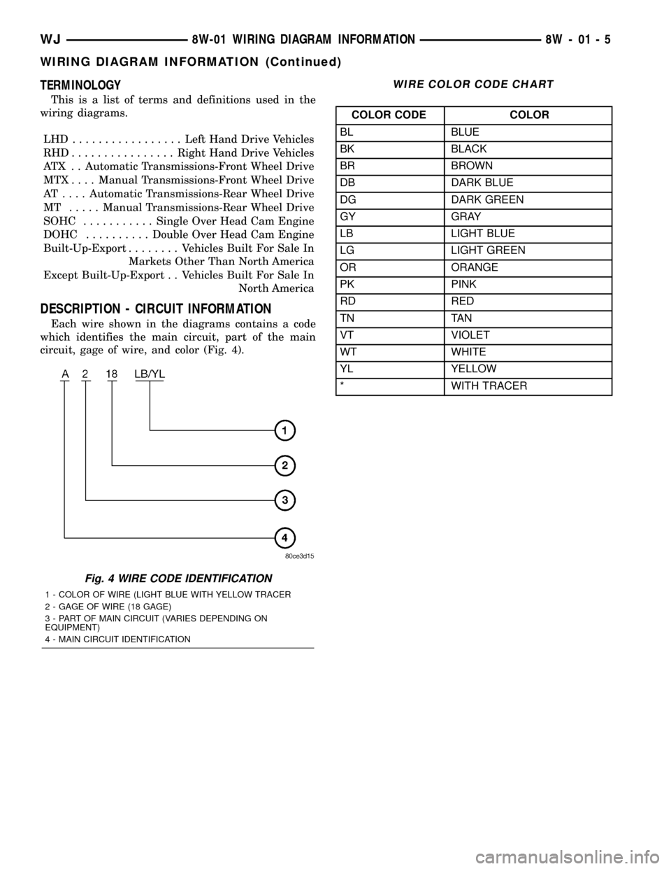
DESCRIPTION - CIRCUIT INFORMATION
Each wire shown in the diagrams contains a code
which identifies the main circuit, part of the main
circuit, gage of wire, and color (Fig. 4).
WIRE COLOR CODE CHART
COLOR CODE COLOR
BL BLUE
BK BLACK
BR BROWN
DB DARK BLUE
DG DARK GREEN
GY GRAY
LB LIGHT BLUE
LG LIGHT GREEN
OR ORANGE
PK PINK
RD RED
TN TAN
VT VIOLET
WT WHITE
YL YELLOW
* WITH TRACER
Fig. 4 WIRE CODE IDENTIFICATION
1 - COLOR OF WIRE (LIGHT BLUE WITH YELLOW TRACER
2 - GAGE OF WIRE (18 GAGE)
3 - PART OF MAIN CIRCUIT (VARIES DEPENDING ON
EQUIPMENT)
4 - MAIN CIRCUIT IDENTIFICATION
WJ8W-01 WIRING DIAGRAM INFORMATION 8W - 01 - 5
WIRING DIAGRAM INFORMATION (Continued)
Page 1120 of 2199
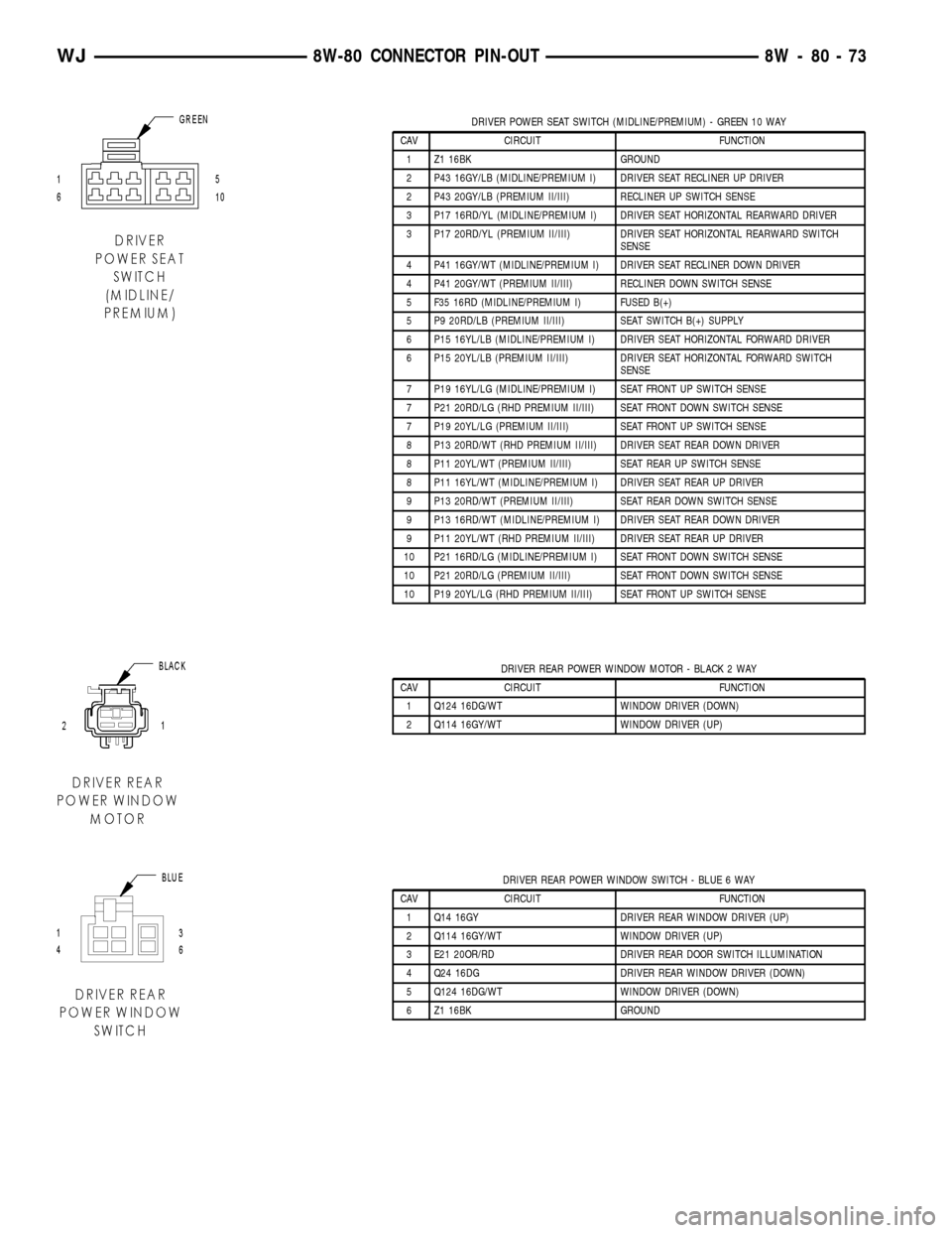
DRIVER POWER SEAT SWITCH (MIDLINE/PREMIUM) - GREEN 10 WAY
CAV CIRCUIT FUNCTION
1 Z1 16BK GROUND
2 P43 16GY/LB (MIDLINE/PREMIUM I) DRIVER SEAT RECLINER UP DRIVER
2 P43 20GY/LB (PREMIUM II/III) RECLINER UP SWITCH SENSE
3 P17 16RD/YL (MIDLINE/PREMIUM I) DRIVER SEAT HORIZONTAL REARWARD DRIVER
3 P17 20RD/YL (PREMIUM II/III) DRIVER SEAT HORIZONTAL REARWARD SWITCH
SENSE
4 P41 16GY/WT (MIDLINE/PREMIUM I) DRIVER SEAT RECLINER DOWN DRIVER
4 P41 20GY/WT (PREMIUM II/III) RECLINER DOWN SWITCH SENSE
5 F35 16RD (MIDLINE/PREMIUM I) FUSED B(+)
5 P9 20RD/LB (PREMIUM II/III) SEAT SWITCH B(+) SUPPLY
6 P15 16YL/LB (MIDLINE/PREMIUM I) DRIVER SEAT HORIZONTAL FORWARD DRIVER
6 P15 20YL/LB (PREMIUM II/III) DRIVER SEAT HORIZONTAL FORWARD SWITCH
SENSE
7 P19 16YL/LG (MIDLINE/PREMIUM I) SEAT FRONT UP SWITCH SENSE
7 P21 20RD/LG (RHD PREMIUM II/III) SEAT FRONT DOWN SWITCH SENSE
7 P19 20YL/LG (PREMIUM II/III) SEAT FRONT UP SWITCH SENSE
8 P13 20RD/WT (RHD PREMIUM II/III) DRIVER SEAT REAR DOWN DRIVER
8 P11 20YL/WT (PREMIUM II/III) SEAT REAR UP SWITCH SENSE
8 P11 16YL/WT (MIDLINE/PREMIUM I) DRIVER SEAT REAR UP DRIVER
9 P13 20RD/WT (PREMIUM II/III) SEAT REAR DOWN SWITCH SENSE
9 P13 16RD/WT (MIDLINE/PREMIUM I) DRIVER SEAT REAR DOWN DRIVER
9 P11 20YL/WT (RHD PREMIUM II/III) DRIVER SEAT REAR UP DRIVER
10 P21 16RD/LG (MIDLINE/PREMIUM I) SEAT FRONT DOWN SWITCH SENSE
10 P21 20RD/LG (PREMIUM II/III) SEAT FRONT DOWN SWITCH SENSE
10 P19 20YL/LG (RHD PREMIUM II/III) SEAT FRONT UP SWITCH SENSE
DRIVER REAR POWER WINDOW MOTOR - BLACK 2 WAY
CAV CIRCUIT FUNCTION
1 Q124 16DG/WT WINDOW DRIVER (DOWN)
2 Q114 16GY/WT WINDOW DRIVER (UP)
DRIVER REAR POWER WINDOW SWITCH - BLUE 6 WAY
CAV CIRCUIT FUNCTION
1 Q14 16GY DRIVER REAR WINDOW DRIVER (UP)
2 Q114 16GY/WT WINDOW DRIVER (UP)
3 E21 20OR/RD DRIVER REAR DOOR SWITCH ILLUMINATION
4 Q24 16DG DRIVER REAR WINDOW DRIVER (DOWN)
5 Q124 16DG/WT WINDOW DRIVER (DOWN)
6 Z1 16BK GROUND
WJ8W-80 CONNECTOR PIN-OUT 8W - 80 - 73
Page 1121 of 2199
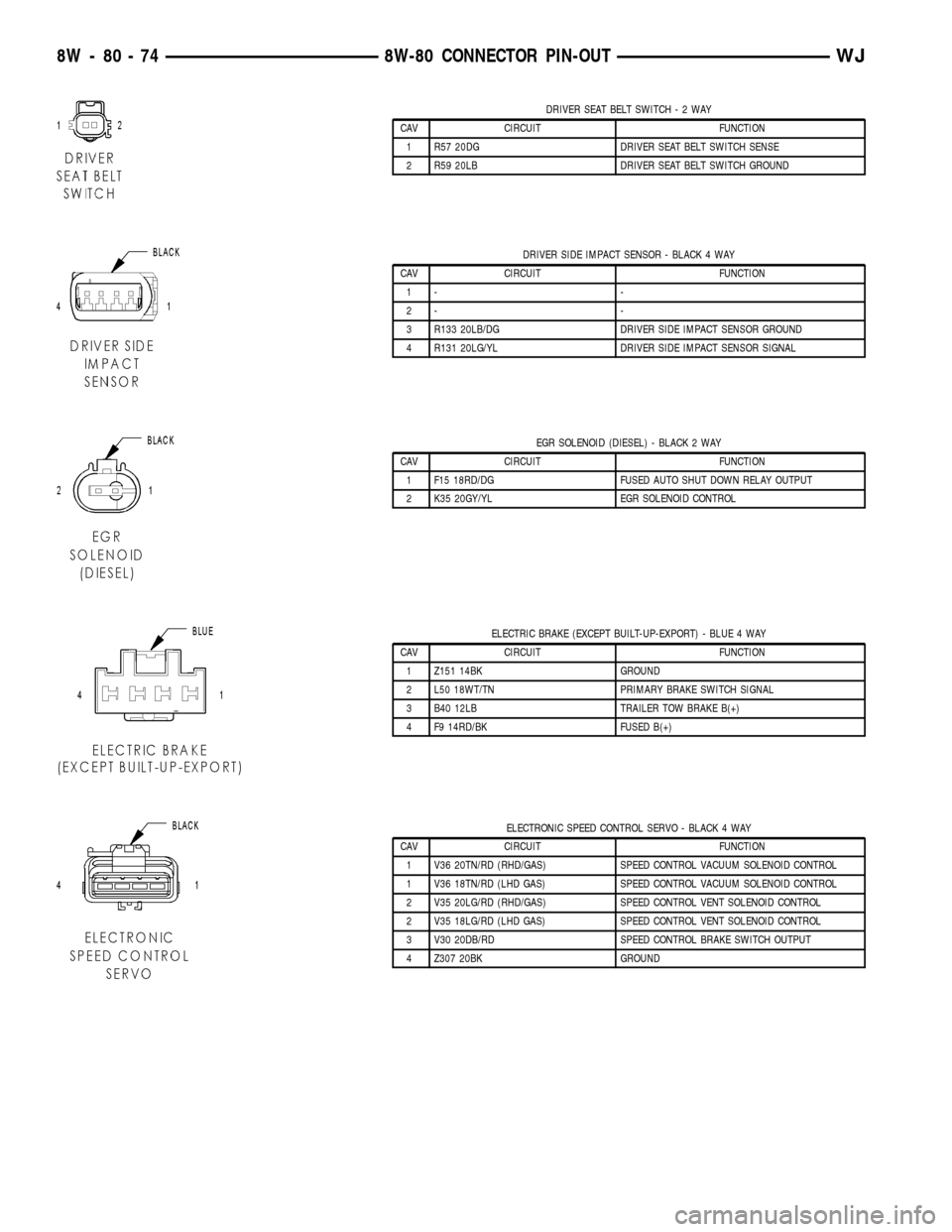
DRIVER SEAT BELT SWITCH-2WAY
CAV CIRCUIT FUNCTION
1 R57 20DG DRIVER SEAT BELT SWITCH SENSE
2 R59 20LB DRIVER SEAT BELT SWITCH GROUND
DRIVER SIDE IMPACT SENSOR - BLACK 4 WAY
CAV CIRCUIT FUNCTION
1- -
2- -
3 R133 20LB/DG DRIVER SIDE IMPACT SENSOR GROUND
4 R131 20LG/YL DRIVER SIDE IMPACT SENSOR SIGNAL
EGR SOLENOID (DIESEL) - BLACK 2 WAY
CAV CIRCUIT FUNCTION
1 F15 18RD/DG FUSED AUTO SHUT DOWN RELAY OUTPUT
2 K35 20GY/YL EGR SOLENOID CONTROL
ELECTRIC BRAKE (EXCEPT BUILT-UP-EXPORT) - BLUE 4 WAY
CAV CIRCUIT FUNCTION
1 Z151 14BK GROUND
2 L50 18WT/TN PRIMARY BRAKE SWITCH SIGNAL
3 B40 12LB TRAILER TOW BRAKE B(+)
4 F9 14RD/BK FUSED B(+)
ELECTRONIC SPEED CONTROL SERVO - BLACK 4 WAY
CAV CIRCUIT FUNCTION
1 V36 20TN/RD (RHD/GAS) SPEED CONTROL VACUUM SOLENOID CONTROL
1 V36 18TN/RD (LHD GAS) SPEED CONTROL VACUUM SOLENOID CONTROL
2 V35 20LG/RD (RHD/GAS) SPEED CONTROL VENT SOLENOID CONTROL
2 V35 18LG/RD (LHD GAS) SPEED CONTROL VENT SOLENOID CONTROL
3 V30 20DB/RD SPEED CONTROL BRAKE SWITCH OUTPUT
4 Z307 20BK GROUND
8W - 80 - 74 8W-80 CONNECTOR PIN-OUTWJ
Page 1153 of 2199
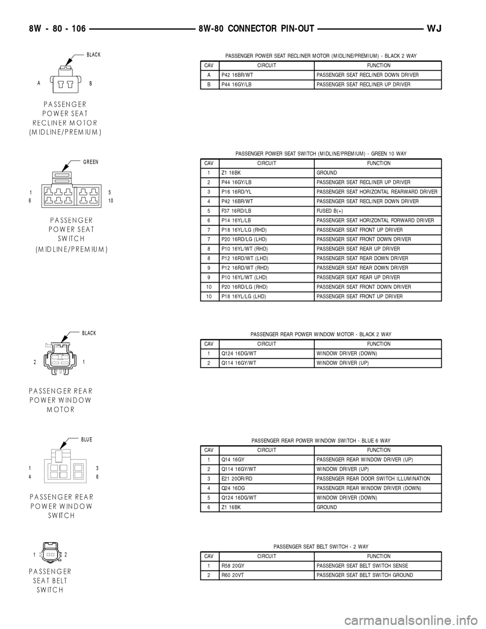
PASSENGER POWER SEAT RECLINER MOTOR (MIDLINE/PREMIUM) - BLACK 2 WAY
CAV CIRCUIT FUNCTION
A P42 16BR/WT PASSENGER SEAT RECLINER DOWN DRIVER
B P44 16GY/LB PASSENGER SEAT RECLINER UP DRIVER
PASSENGER POWER SEAT SWITCH (MIDLINE/PREMIUM) - GREEN 10 WAY
CAV CIRCUIT FUNCTION
1 Z1 16BK GROUND
2 P44 16GY/LB PASSENGER SEAT RECLINER UP DRIVER
3 P16 16RD/YL PASSENGER SEAT HORIZONTAL REARWARD DRIVER
4 P42 16BR/WT PASSENGER SEAT RECLINER DOWN DRIVER
5 F37 16RD/LB FUSED B(+)
6 P14 16YL/LB PASSENGER SEAT HORIZONTAL FORWARD DRIVER
7 P18 16YL/LG (RHD) PASSENGER SEAT FRONT UP DRIVER
7 P20 16RD/LG (LHD) PASSENGER SEAT FRONT DOWN DRIVER
8 P10 16YL/WT (RHD) PASSENGER SEAT REAR UP DRIVER
8 P12 16RD/WT (LHD) PASSENGER SEAT REAR DOWN DRIVER
9 P12 16RD/WT (RHD) PASSENGER SEAT REAR DOWN DRIVER
9 P10 16YL/WT (LHD) PASSENGER SEAT REAR UP DRIVER
10 P20 16RD/LG (RHD) PASSENGER SEAT FRONT DOWN DRIVER
10 P18 16YL/LG (LHD) PASSENGER SEAT FRONT UP DRIVER
PASSENGER REAR POWER WINDOW MOTOR - BLACK 2 WAY
CAV CIRCUIT FUNCTION
1 Q124 16DG/WT WINDOW DRIVER (DOWN)
2 Q114 16GY/WT WINDOW DRIVER (UP)
PASSENGER REAR POWER WINDOW SWITCH - BLUE 6 WAY
CAV CIRCUIT FUNCTION
1 Q14 16GY PASSENGER REAR WINDOW DRIVER (UP)
2 Q114 16GY/WT WINDOW DRIVER (UP)
3 E21 20OR/RD PASSENGER REAR DOOR SWITCH ILLUMINATION
4 Q24 16DG PASSENGER REAR WINDOW DRIVER (DOWN)
5 Q124 16DG/WT WINDOW DRIVER (DOWN)
6 Z1 16BK GROUND
PASSENGER SEAT BELT SWITCH-2WAY
CAV CIRCUIT FUNCTION
1 R58 20GY PASSENGER SEAT BELT SWITCH SENSE
2 R60 20VT PASSENGER SEAT BELT SWITCH GROUND
8W - 80 - 106 8W-80 CONNECTOR PIN-OUTWJ
Page 1160 of 2199
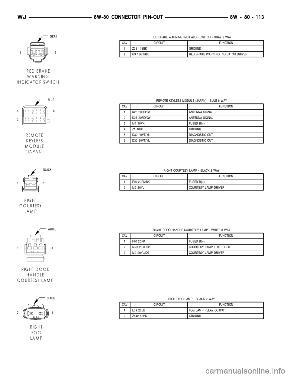
RED BRAKE WARNING INDICATOR SWITCH - GRAY 2 WAY
CAV CIRCUIT FUNCTION
1 Z231 18BK GROUND
2 G9 18GY/BK RED BRAKE WARNING INDICATOR DRIVER
REMOTE KEYLESS MODULE (JAPAN) - BLUE 6 WAY
CAV CIRCUIT FUNCTION
1 K25 20RD/GY ANTENNA SIGNAL
2 K25 20RD/GY ANTENNA SIGNAL
3 M1 18PK FUSED B(+)
4 Z1 18BK GROUND
5 D30 20VT/YL DIAGNOSTIC OUT
6 D30 20VT/YL DIAGNOSTIC OUT
RIGHT COURTESY LAMP - BLACK 2 WAY
CAV CIRCUIT FUNCTION
1 F70 20PK/BK FUSED B(+)
2 M2 20YL COURTESY LAMP DRIVER
RIGHT DOOR HANDLE COURTESY LAMP - WHITE 3 WAY
CAV CIRCUIT FUNCTION
1 F70 20PK FUSED B(+)
2 M20 20YL/BK COURTESY LAMP LOAD SHED
3 M2 20YL/DG COURTESY LAMP DRIVER
RIGHT FOG LAMP - BLACK 2 WAY
CAV CIRCUIT FUNCTION
1 L39 20LB FOG LAMP RELAY OUTPUT
2 Z142 18BK GROUND
WJ8W-80 CONNECTOR PIN-OUT 8W - 80 - 113
Page 1278 of 2199
is needed to provide the correct clearance. Refer to
CONNECTING ROD BEARING FITTING CHART .
CONNECTING ROD BEARING FITTING CHART
CRANKSHAFT JOURNAL CORRESPONDING ROD BEARING INSERT
Color Code Diameter Upper Insert Size Lower Insert Size
Yellow53.2257 - 53.2079 mm
Yellow - Standard Yellow - Standard
(2.0955 - 2.0948 in.)
Orange53.2079 - 53.1901 mm
Yellow - StandardBlue - Undersize (2.0948 - 2.0941 in.)
0.0178 mm (0.0007 in.) 0.025 mm (0.001 in.)
Undersize
Blue53.1901 - 53.1724 mm
Blue - Undersize Blue - Undersize (2.0941 - 2.0934 in.)
0.0356 mm (0.0014 in.) 0.025 mm (0.001 in.) 0.025 mm (0.001 in.)
Undersize
Red52.9717 - 52.9539 mm
Red - Undersize Red - Undersize (2.0855 - 2.0848 in.)
0.254 mm (0.010 in.) 0.254 mm (0.010 in.) 0.254 mm (0.010 in.)
Undersize
(11)FOR EXAMPLE:If the initial clearance was
0.0762 mm (0.003 inch), 0.025 mm (0.001 inch)
undersize inserts would reduce the clearance by
0.025 mm (0.001 inch). The clearance would be 0.002
inch and within specification. A 0.051 mm (0.002
inch) undersize insert would reduce the initial clear-
ance an additional 0.013 mm (0.0005 inch). The
clearance would then be 0.038 mm (0.0015 inch).
(12) Repeat the Plastigage measurement to verify
your bearing selection prior to final assembly.
(13) Once you have selected the proper insert,
install the insert and cap. Tighten the connecting rod
bolts to 45 N´m (33 ft. lbs.) torque.
SIDE CLEARANCE MEASUREMENT
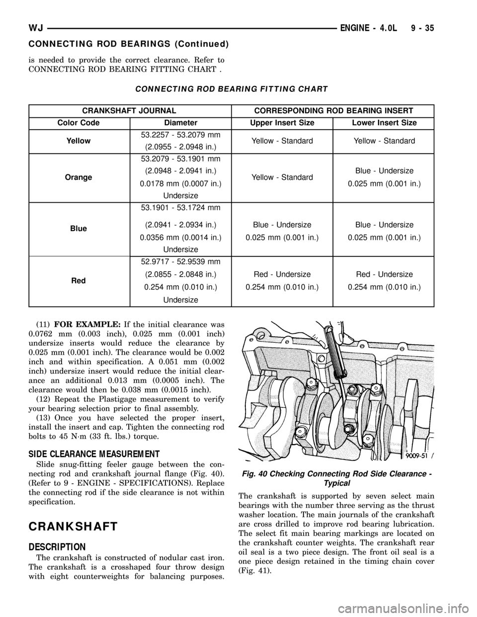
Slide snug-fitting feeler gauge between the con-
necting rod and crankshaft journal flange (Fig. 40).
(Refer to 9 - ENGINE - SPECIFICATIONS). Replace
the connecting rod if the side clearance is not within
specification.
CRANKSHAFT
DESCRIPTION
The crankshaft is constructed of nodular cast iron.
The crankshaft is a crosshaped four throw design
with eight counterweights for balancing purposes.The crankshaft is supported by seven select main
bearings with the number three serving as the thrust
washer location. The main journals of the crankshaft
are cross drilled to improve rod bearing lubrication.
The select fit main bearing markings are located on
the crankshaft counter weights. The crankshaft rear
oil seal is a two piece design. The front oil seal is a
one piece design retained in the timing chain cover
(Fig. 41).
Fig. 40 Checking Connecting Rod Side Clearance -
Typical
WJENGINE - 4.0L 9 - 35
CONNECTING ROD BEARINGS (Continued)
Page 1281 of 2199
MAIN BEARING FITTING CHART
Crankshaft Journals #1-6 Corresponding Crankshaft Bearing Insert
Color Code Diameter Upper Insert Size Lower Insert Size
Yellow63.5025 -63.4898 mm
Yellow - Standard Yellow - Standard
(2.5001 - 2.4996 in.)
Orange63.4898 - 63.4771 mm
Yellow - StandardBlue - Undersize
0.025 mm (0.001 in.) (2.4996 - 2.4991 in.)
0.0127 mm (0.0005 in.)
Undersize
Blue63.4771 - 63.4644 mm
Blue - Undersize
0.025 mm (0.001 in.)Blue - Undersize
0.025 mm (0.001 in.) (2.4991 - 2.4986 in.)
0.0254 mm (0.001 in.)
Undersize
Green63.4644 - 63.4517 mm
Blue - Undersize
0.025 mm (0.001 in.)Green - Undersize
0.051 mm (0.002 in.) (2.4986 - 2.4981 in.)
0.0381 mm (0.0015 in.)
Undersize
Red63.2485 - 63.2358 mm
Red - Undersize
0.254 mm (0.010 in.)Red - Undersize
0.254 mm (0.010 in.) (2.4901 - 2.4896 in.)
0.254 mm (0.010 in.)
Undersize
Crankshaft Journal #7 Only Corresponding Bearing Insert
Color Code Diameter Upper Insert Size Lower Insert Size
Yellow63.4873 - 63.4746 mm
Yellow - Standard Yellow - Standard
(2.4995 - 2.4990 in.)
Orange63.4746 - 63.4619 mm
Yellow - StandardBlue - Undersize
0.025 mm (0.001 in.) (2.4990 - 2.4985 in.)
0.0127 mm (0.0005 in.)
Undersize
Blue63.4619 - 63.4492 mm
Blue - Undersize
0.025 mm (0.001 in.)Blue - Undersize
0.025 mm (0.001 in.) (2.4985 - 2.4980 in.)
0.0254 mm (0.001 in.)
Undersize
Green63.4492 - 63.4365 mm
Blue - Undersize
0.025 mm (0.001 in.)Green - Undersize
0.051 mm (0.002 in.) (2.4980 - 2.4975 in.)
0.0381 mm (0.0015 in.)
Undersize
Red63.2333 - 63.2206 mm
Red - Undersize
0.254 mm (0.010 in.)Red - Undersize
0.254 mm (0.010 in.) (2.4895 - 2.4890 in.)
0.254 mm (0.010 in.)
Undersize
9 - 38 ENGINE - 4.0LWJ
CRANKSHAFT MAIN BEARINGS (Continued)
Page 1337 of 2199
INTAKE/EXHAUST VALVES &
SEATS
DESCRIPTION
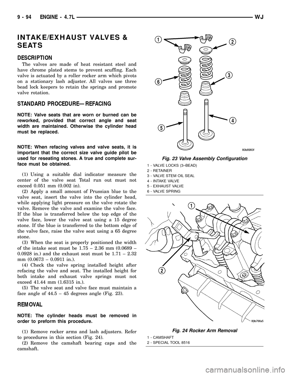
The valves are made of heat resistant steel and
have chrome plated stems to prevent scuffing. Each
valve is actuated by a roller rocker arm which pivots
on a stationary lash adjuster. All valves use three
bead lock keepers to retain the springs and promote
valve rotation.
STANDARD PROCEDUREÐREFACING
NOTE: Valve seats that are worn or burned can be
reworked, provided that correct angle and seat
width are maintained. Otherwise the cylinder head
must be replaced.
NOTE: When refacing valves and valve seats, it is
important that the correct size valve guide pilot be
used for reseating stones. A true and complete sur-
face must be obtained.
(1) Using a suitable dial indicator measure the
center of the valve seat Total run out must not
exceed 0.051 mm (0.002 in).
(2) Apply a small amount of Prussian blue to the
valve seat, insert the valve into the cylinder head,
while applying light pressure on the valve rotate the
valve. Remove the valve and examine the valve face.
If the blue is transferred below the top edge of the
valve face, lower the valve seat using a 15 degree
stone. If the blue is transferred to the bottom edge of
the valve face, raise the valve seat using a 65 degree
stone.
(3) When the seat is properly positioned the width
of the intake seat must be 1.75 ± 2.36 mm (0.0689 ±
0.0928 in.) and the exhaust seat must be 1.71 ± 2.32
mm (0.0673 ± 0.0911 in.).
(4) Check the valve spring installed height after
refacing the valve and seat. The installed height for
both intake and exhaust valve springs must not
exceed 41.44 mm (1.6315 in.).
(5) The valve seat and valve face must maintain a
face angle of 44.5 ± 45 degrees angle (Fig. 23).
REMOVAL
NOTE: The cylinder heads must be removed in
order to preform this procedure.
(1) Remove rocker arms and lash adjusters. Refer
to procedures in this section (Fig. 24).
(2) Remove the camshaft bearing caps and the
camshaft.
Fig. 23 Valve Assembly Configuration
1 - VALVE LOCKS (3±BEAD)
2 - RETAINER
3 - VALVE STEM OIL SEAL
4 - INTAKE VALVE
5 - EXHAUST VALVE
6 - VALVE SPRING
Fig. 24 Rocker Arm Removal
1 - CAMSHAFT
2 - SPECIAL TOOL 8516
9 - 94 ENGINE - 4.7LWJ
Page 1348 of 2199

STANDARD PROCEDUREÐREFACING
NOTE: Valve seats that are worn or burned can be
reworked, provided that correct angle and seat
width are maintained. Otherwise the cylinder head
must be replaced.
NOTE: When refacing valves and valve seats, it is
important that the correct size valve guide pilot be
used for reseating stones. A true and complete sur-
face must be obtained.
(1) Using a suitable dial indicator measure the
center of the valve seat Total run out must not
exceed 0.051 mm (0.002 in).
(2) Apply a small amount of Prussian blue to the
valve seat, insert the valve into the cylinder head,
while applying light pressure on the valve rotate the
valve. Remove the valve and examine the valve face.
If the blue is transferred below the top edge of the
valve face, lower the valve seat using a 15 degree
stone. If the blue is transferred to the bottom edge of
the valve face, raise the valve seat using a 65 degree
stone.
(3) When the seat is properly positioned the width
of the intake seat must be 1.75 ± 2.36 mm (0.0689 ±
0.0928 in.) and the exhaust seat must be 1.71 ± 2.32
mm (0.0673 ± 0.0911 in.).
(4) Check the valve spring installed height after
refacing the valve and seat. The installed height for
both intake and exhaust valve springs must not
exceed 41.44 mm (1.6315 in.).
(5) The valve seat and valve face must maintain a
face angle of 44.5 ± 45 degrees angle (Fig. 39).
REMOVAL
NOTE: The cylinder heads must be removed in
order to preform this procedure.
(1) Remove rocker arms and lash adjusters. Refer
to procedures in this section (Fig. 40).
(2) Remove the camshaft bearing caps and the
camshaft.
NOTE: All eight valve springs and valves are
removed in the same manner; this procedure only
covers one valve and valve spring.
(3) Using Special Tool C-3422±B or C-3422±C
Valve Spring Compressor and Special tool 8519
Adapter, compress the valve spring.
NOTE: It may be necessary to tap the top of the
valve spring to loosen the spring retainers locks
enough to be removed.
Fig. 39 Valve Assembly Configuration
1 - VALVE LOCKS (3±BEAD)
2 - RETAINER
3 - VALVE STEM OIL SEAL
4 - INTAKE VALVE
5 - EXHAUST VALVE
6 - VALVE SPRING
Fig. 40 Rocker Arm Removal
1 - CAMSHAFT
2 - SPECIAL TOOL 8516
WJENGINE - 4.7L 9 - 105
INTAKE/EXHAUST VALVES & SEATS (Continued)