group 8w wiring JEEP GRAND CHEROKEE 2002 WJ / 2.G User Guide
[x] Cancel search | Manufacturer: JEEP, Model Year: 2002, Model line: GRAND CHEROKEE, Model: JEEP GRAND CHEROKEE 2002 WJ / 2.GPages: 2199, PDF Size: 76.01 MB
Page 412 of 2199

INSTALLATION
4.7L High-Output Engine Only
NOTE: The left sensor is identified by an identifica-
tion tag (LEFT). It is also identified by a larger bolt
head. The Powertrain Control Module (PCM) must
have and know the correct sensor left/right posi-
tions. Do not mix the sensor locations.
(1) Thoroughly clean knock sensor mounting holes.
(2) Install sensors (Fig. 22) into cylinder block.
NOTE: Over or under tightening the sensor mount-
ing bolts will affect knock sensor performance, pos-
sibly causing improper spark control. Always use
the specified torque when installing the knock sen-
sors. The torque for the knock senor bolt is rela-
tively light for an 8mm bolt.
NOTE: Note foam strip on bolt threads. This foam is
used only to retain the bolts to sensors for plant
assembly. It is not used as a sealant. Do not apply
any adhesive, sealant or thread locking compound
to these bolts.
(3) Install and tighten mounting bolts.Bolt
torque is critical.Refer to torque specification.
(4) Install intake manifold. Refer to Engine sec-
tion.
(5) Connect knock sensor pigtail wiring harness to
engine wiring harness near right / rear of intake
manifold (Fig. 23).
SPARK PLUG
DESCRIPTION
Both the 4.0L 6-cylinder and the 4.7L V-8 engine
use resistor type spark plugs. Standard 4.7L V-8
engines are equipped with ªfired in suppressor sealº
type spark plugs using a copper core ground elec-
trode. High-Output (H.O.) 4.7L V-8 engines are
equipped with unique plugs using a platinum rivet
located on the tip of the center electrode.
Because of the use of an aluminum cylinder head
on the 4.7L engine, spark plug torque is very critical.
To prevent possible pre-ignition and/or mechanical
engine damage, the correct type/heat range/number
spark plug must be used.Do not substitute any
other spark plug on the 4.7L H.O. engine. Seri-
ous engine damage may occur.
Plugs on both engines have resistance values rang-
ing from 6,000 to 20,000 ohms (when checked with at
least a 1000 volt spark plug tester).Do not use an
ohmmeter to check the resistance values of thespark plugs. Inaccurate readings will result.
Remove the spark plugs and examine them for
burned electrodes and fouled, cracked or broken por-
celain insulators. Keep plugs arranged in the order
in which they were removed from the engine. A sin-
gle plug displaying an abnormal condition indicates
that a problem exists in the corresponding cylinder.
Replace spark plugs at the intervals recommended in
Group O, Lubrication and Maintenance.
EXCEPT 4.7L H.O. ENGINE :Spark plugs that
have low mileage may be cleaned and reused if not
otherwise defective, carbon or oil fouled. Also refer to
Spark Plug Conditions.4.7L H.O. ENGINE :Never
clean spark plugs on the 4.7L H.O. engine. Damage
to the platinum rivet will result.
CAUTION: EXCEPT 4.7L H.O. ENGINE : Never use a
motorized wire wheel brush to clean the spark
plugs. Metallic deposits will remain on the spark
plug insulator and will cause plug misfire.
H.O. Gap Adjustment:If equipped with the 4.7L
H.O. engine, do not use a wire-type gapping tool as
damage to the platinum rivet on the center electrode
may occur. Use a tapered-type gauge (Fig. 24).
DIAGNOSIS AND TESTING - SPARK PLUG
CONDITIONS
NORMAL OPERATING
The few deposits present on the spark plug will
probably be light tan or slightly gray in color. This is
evident with most grades of commercial gasoline
Fig. 24 PLUG GAP - 4.7L H.O.
1 - TAPER GAUGE
WJIGNITION CONTROL 8I - 15
KNOCK SENSOR (Continued)
Page 465 of 2199

CONDITION POSSIBLE CAUSES CORRECTION
FOG LAMPS DO NOT
ILLUMINATE1. Blown fuse for fog lamp. 1. Replace fuse. Refer to Electrical, Wiring
Information.
2. No Z1-ground at fog lamps. 2. Repair circuit ground. Refer to Electrical,
Wiring Information.
3. Faulty multifunction switch. 3. Refer to Electrical, Wiring Information.
4. Broken connector terminal or wire
splice in fog lamp circuit.4. Repair connector terminal or wire splice.
5. Defective or burned out bulb. 5. Replace bulb.
DAYTIME RUNNING LAMP
CONDITION POSSIBLE CAUSES CORRECTION
DAYTIME RUNNING LAMPS DO
NOT WORK1. Poor connection at DRL module. 1. Secure connector on DRL
module.
2. Parking brake engaged. 2. Disengage parking brake.
3. Parking brake circuit shorted to
ground.3. Check cluster telltale, refer to
Group 8W.
4. Headlamp circuit shorted to
ground.4. Refer to Group 8W.
5. Defective DRL relay. 5. Replace DRL relay.
6. Body controller not programed
with Canadian country code.6. Check country code.
7. DRL relay is missing. 7. Install DRL relay.
8. Blown fuse for DRL. 8. Replace fuse refer to Electrical,
Wiring Information.
Clicking or chattering when DRL is
on.1. Mechanical relay is installed in
the junction block.1. Ensure that the DRL relay is
installed in the proper socket in
junction block, and that no
mechanical relay exists in the low
beam socket.
DIAGNOSIS AND TESTING Ð HEADLAMP
WARNING: EYE PROTECTION SHOULD BE USED
WHEN SERVICING GLASS COMPONENTS. PER-
SONAL INJURY CAN RESULT.
CAUTION: Do not touch the glass of halogen bulbs
with fingers or other possibly oily surface, reduced
bulb life will result. Do not use bulbs other than
those indicated in the Bulb Application table. Dam-
age to lamp and/or Daytime Running Lamp Module
can result. Do not use fuses, circuit breakers or
relays having greater amperage value than indi-
cated on the fuse panel or in the Owners Manual.
Each vehicle is equipped with various lamp assem-
blies. A good power feed and ground are necessary forproper lighting operation. Grounding is provided by
the lamp socket when it comes in contact with the
metal body, or through a separate ground wire.
When changing lamp bulbs check the socket for
corrosion. If corrosion is present, clean it with a wire
brush and coat the inside of the socket lightly with
Mopar Multi-Purpose Grease or equivalent.
REMOVAL - BULB
(1) Remove the headlamp.
(2) Turn the bulb socket one quarter turn counter
clockwise.
(3) Remove the socket from lamp (Fig. 13).
(4) Remove the bulb from socket.
8L - 14 LAMPS/LIGHTING - EXTERIORWJ
HEADLAMP (Continued)
Page 481 of 2199

wired between a body ground, the Body Control Mod-
ule (BCM) and the rear wiper motor module through
the liftgate and body wire harnesses.
The liftgate flip-up glass ajar switch cannot be
adjusted or repaired and, if faulty or damaged, the
liftgate flip-up glass latch unit must be replaced.
(Refer to 23 - BODY/DECKLID/HATCH/LIFTGATE/
TAILGATE/FLIP-UP GLASS LATCH - REMOVAL)
for the service procedures. For complete circuit dia-
grams, refer to the appropriate wiring information.
DESCRIPTION - LIFTGATE AJAR SWITCH
The two liftgate ajar switches are integral to the
two liftgate latch mechanisms. The two liftgate ajar
switches are actuated by the liftgate latch mecha-
nisms, and are hard wired with each other between a
body ground and the Body Control Module (BCM)
through the liftgate and body wire harnesses.
The liftgate ajar switches cannot be adjusted or
repaired and, if faulty or damaged, the liftgate latch
unit must be replaced. (Refer to 23 - BODY/DECK-
LID/HATCH/LIFTGATE/TAILGATE/LATCH -
REMOVAL) for the service procedures. For complete
circuit diagrams, refer to the appropriate wiring
information.
OPERATION
OPERATION - DOOR AJAR SWITCH
The front door ajar switches close a path to ground
for the DDM or the PDM when a front door is
opened, and opens the ground path when a front door
is closed. The rear door ajar switches close a path to
ground for the BCM when a rear door is opened, and
opens the ground path when a rear door is closed.
The DDM, PDM, or BCM read the switch status then
send the proper switch status messages to other
modules over the Programmable Communications
Interface (PCI) data bus network. The door ajar
switch status message is used by the BCM as an
input for Vehicle Theft Security System (VTSS) oper-
ation.
OPERATION - FLIP UP GLASS AJAR SWITCH
The liftgate flip-up glass ajar switch can close a
path to ground for the BCM and the rear wiper
motor module when the liftgate flip-up glass is
opened, and opens the ground path when the liftgate
flip-up glass is closed. The rear wiper motor module
uses the liftgate flip-up glass ajar switch input to
control the rear wiper operation, and will park the
rear wiper blade if this input indicates that the lift-
gate flip-up glass is ajar. The BCM reads the switch
status then sends the proper switch status message
to other modules over the Programmable Communi-cations Interface (PCI) data bus network. The liftgate
flip-up glass ajar switch status message is used by
the BCM as an input for Vehicle Theft Security Sys-
tem (VTSS) operation.
OPERATION - LIFTGATE AJAR SWITCH
Each of the liftgate ajar switches can close a path
to ground for the BCM when the liftgate is opened,
and opens the ground path when the liftgate is
closed. The BCM reads the switch status then sends
the proper switch status message to other modules
over the Programmable Communications Interface
(PCI) data bus network. The liftgate ajar switch sta-
tus message is used by the BCM as an input for
Vehicle Theft Security System (VTSS) operation.
DIAGNOSIS AND TESTING - DOOR AJAR
SWITCH
The following diagnosis and testing is only
for the chime functions. For interior lamp diag-
nosis, refer to the appropriate wiring informa-
tion.The driver door ajar switch is hard wired to the
Driver Door Module (DDM). The DDM communicates
the switch status to the other modules in the vehicle
on the Programmable Communications Interface
(PCI) data bus network. The following test will diag-
nose a faulty driver door ajar switch and circuits. For
complete circuit diagrams, refer to the appropriate
wiring information.
WARNING: ON VEHICLES EQUIPPED WITH AIR-
BAGS, REFER TO ELECTRICAL, RESTRAINTS
BEFORE ATTEMPTING ANY STEERING WHEEL,
STEERING COLUMN, OR INSTRUMENT PANEL
COMPONENT DIAGNOSIS OR SERVICE. FAILURE
TO TAKE THE PROPER PRECAUTIONS COULD
RESULT IN ACCIDENTAL AIRBAG DEPLOYMENT
AND POSSIBLE PERSONAL INJURY.
(1) Check that the interior lighting switch on the
control stalk of the left multi-function switch is not
in the dome lamp disable position. Open the driver
side front door and note whether the interior lamps
light. They should light. If OK, refer to Key-In Igni-
tion Switch in the Diagnosis and Testing section of
this group for further diagnosis of the chime warning
system. If not OK, go to Step 2.
(2) Disconnect and isolate the battery negative
cable. Remove the trim panel from the driver front
door and disconnect the 4-way door wire harness con-
nector from the front door latch connector. Check for
continuity between the ground circuit of the 4-way
door wire harness connector and a good ground.
There should be continuity. If OK, go to Step 3. If not
OK, repair the ground circuit.
8L - 30 LAMPS/LIGHTING - INTERIORWJ
DOOR AJAR SWITCH (Continued)
Page 492 of 2199

OPERATION
The EVIC has access to both non-switched and
ignition switched sources of battery current so that
some of its features remain operational at any time,
while others may only operate with the ignition
switch in the On position. When the ignition switch
is turned to the On position, the EVIC module VFD
will return to the last function being displayed before
the ignition was turned to the Off position.
The compass/temperature display is the normal
EVIC display. With the ignition switch in the On
position, momentarily depressing and releasing the
C/T (compass/temperature) push button switch will
cause the EVIC to return to the compass/tempera-
ture/trip computer display mode from any other
mode. While in the compass/temperature/trip com-
puter display mode, momentarily depressing and
releasing the Step push button will step through the
available trip computer display options.
The EVIC trip computer features several functions
that can be reset. The functions that can be reset
are: average fuel economy, trip odometer and elapsed
time. With the ignition switch in the On position and
with one of the functions of the trip computer that
can be reset currently displayed, depressing the
Reset push button twice within three seconds will
perform a global reset, and all of the trip computer
information that can be reset will be reset to zero.
With the ignition switch in the On position and the
function that is to be reset currently displayed,
momentarily depressing and releasing the Reset
push button once will perform a local reset, and only
the value of the displayed function will be reset to
zero. A global or local reset will only occur if the
function currently displayed is a function that can be
reset. The distance to service function can also be
reset using the local reset method, but it will reset
back to the Service Interval distance that is set in
the EVIC programmable features mode. Refer to
ELECTRONIC VEHICLE INFORMATION CEN-
TER PROGRAMMINGin the Service Procedures
section of this group for more information on setting
the Service Interval.
For more information on the features, control func-
tions and setting procedures for the EVIC module,
see the owner's manual in the vehicle glove box.
DIAGNOSIS AND TESTING - ELECTRONIC
VEHICLE INFORMATION CENTER
If the problem with the Electronic Vehicle Informa-
tion Center (EVIC) is a temperature reading of 130É
F or -40ÉF shown in the compass/temperature dis-
play, refer toAmbient Temperature Sensor Diag-
nosis and Testingin this group. If the problem with
the EVIC is an inaccurate or scrambled display, refer
toSelf-Diagnostic Testin this group. If the prob-lem with the EVIC is incorrect Vacuum Fluorescent
Display (VFD) dimming levels, use a DRBtscan tool
and the proper Diagnostic Procedures manual to test
for the correct dimming message inputs being
received from the Body Control Module (BCM) over
the Programmable Communications Interface (PCI)
data bus. If the problem is a no-display condition,
use the following procedures. For complete circuit
diagrams, refer toOverhead Consolein Wiring
Diagrams.
(1) Check the fused B(+) fuse in the junction block.
If OK, go to Step 2. If not OK, repair the shorted cir-
cuit or component as required and replace the faulty
fuse.
(2) Check for battery voltage at the fused B(+) fuse
in the junction block. If OK, go to Step 3. If not OK,
repair the open fused B(+) circuit to the fused B(+)
fuse in the PDC as required.
(3) Check the fused ignition switch output (run/
start) fuse in the junction block. If OK, go to Step 4.
If not OK, repair the shorted circuit or component as
required and replace the faulty fuse.
(4) Turn the ignition switch to the On position.
Check for battery voltage at the fused ignition switch
output (run/start) fuse in the junction block. If OK,
go to Step 5. If not OK, repair the open fused ignition
switch output (run/start) circuit to the ignition switch
as required.
(5) Turn the ignition switch to the Off position.
Disconnect and isolate the battery negative cable.
Remove the overhead console. Check for continuity
between the ground circuit cavity of the roof wire
harness connector for the EVIC module and a good
ground. There should be continuity. If OK, go to Step
6. If not OK, repair the open ground circuit to ground
as required.
(6) Connect the battery negative cable. Check for
battery voltage at the fused B(+) circuit cavity of the
roof wire harness connector for the EVIC module. If
OK, go to Step 7. If not OK, repair the open fused
B(+) circuit to the fused B(+) fuse in the junction
block as required.
(7) Turn the ignition switch to the On position.
Check for battery voltage at the fused ignition switch
output (run/start) circuit cavity of the roof wire har-
ness connector for the EVIC module. If OK, refer to
Self-Diagnostic Testbelow for further diagnosis of
the EVIC module and the PCI data bus. If not OK,
repair the open fused ignition switch output (run/
start) circuit to the fuse in the junction block as
required.
SELF-DIAGNOSTIC TEST
A self-diagnostic test is used to determine that the
EVIC module is operating properly, and that all PCI
WJMESSAGE SYSTEMS 8M - 9
ELECTRONIC VEHICLE INFO CENTER (Continued)
Page 494 of 2199

NOTE: If the vehicle is equipped with the Tire Pres-
sure Monitoring (TPM) System, and the overhead
console electronics module is removed or replaced,
the TPM system will need to be retrained. Refer to
the Tires/Wheels section of this manual for the pro-
cedure.
UNIVERSAL TRANSMITTER
DESCRIPTION
The Grand Cherokee Limited model has a Univer-
sal Garage Door Opener (UGDO) transceiver as stan-
dard factory-installed equipment. The UGDO is
optional on Laredo models. The UGDO transceiver is
integral to the Electronic Vehicle Information Center
(EVIC), which is located in the overhead console. The
only visible component of the UGDO are the three
transmitter push buttons centered between the four
EVIC push buttons located just rearward of the
EVIC display screen in the overhead console. The
three UGDO transmitter push buttons are identified
with one, two or three dots so that they be easily
identified by sight.
Each of the three UGDO transmitter push buttons
controls an independent radio transmitter channel.
Each of these three channels can be trained to trans-
mit a different radio frequency signal for the remoteoperation of garage door openers, motorized gate
openers, home or office lighting, security systems or
just about any other device that can be equipped
with a radio receiver in the 288 to 410 MegaHertz
(MHz) frequency range for remote operation. The
UGDO is capable of operating systems using either
rolling code or non-rolling code technology.
The EVIC module displays messages and a small
house-shaped icon with one, two or three dots corre-
sponding to the three transmitter buttons to indicate
the status of the UGDO. The EVIC messages are:
²Cleared Channels- Indicates that all of the
transmitter codes stored in the UGDO have been suc-
cessfully cleared.
²Training- Indicates that the UGDO is in its
transmitter learning mode.
²Trained- Indicates that the UGDO has success-
fully acquired a new transmitter code.
²Transmit- Indicates that a trained UGDO
transmitter button has been depressed and that the
UGDO is transmitting.
The UGDO cannot be repaired, and is available for
service only as a unit with the EVIC module. This
unit includes the push button switches and the plas-
tic module. If any of these components are faulty or
damaged, the complete EVIC module must be
replaced.
OPERATION
The universal transmitter operates on a non-
switched source of battery current so the unit will
remain functional, regardless of the ignition switch
position. For more information on the features, pro-
gramming procedures and operation of the universal
transmitter, see the owner's manual in the vehicle
glove box.
DIAGNOSIS AND TESTING - UNIVERSAL
TRANSMITTER
If the Universal Transmitter is inoperative, but the
Electronic Vehicle Information Center (EVIC) is oper-
ating normally, see the owner's manual in the vehicle
glove box for instructions on training the Transmit-
ter. Retrain the Transmitter with a known good
transmitter as instructed in the owner's manual and
test the Transmitter operation again. If the unit is
still inoperative, replace the faulty Transmitter and
EVIC module as a unit. If both the Transmitter and
the EVIC module are inoperative, refer toElec-
tronic Vehicle Information Center Diagnosis
and Testingin this group for further diagnosis. For
complete circuit diagrams, refer toWiring Dia-
grams.
Fig. 5 Top of Overhead Console
1 - OVERHEAD CONSOLE HOUSING
2 - EVIC MODULE
3 - ILLUMINATION LAMPS
4 - SCREWS (4)
WJMESSAGE SYSTEMS 8M - 11
ELECTRONIC VEHICLE INFO CENTER (Continued)
Page 495 of 2199

AMBIENT TEMP SENSOR
DESCRIPTION
Ambient air temperature is monitored by the Elec-
tronic Vehicle Information Center (EVIC) through
ambient temperature messages received from the
Body Control Module (BCM) over the Programmable
Communications Interface (PCI) data bus network.
The BCM receives a hard wired input from the ambi-
ent temperature sensor. The ambient temperature
sensor is a variable resistor mounted to a bracket
that is secured with a screw to the right side of the
headlamp mounting module grille opening, behind
the radiator grille and in front of the engine compart-
ment.
Refer toBody Control Modulein Electronic Con-
trol Modules. For complete circuit diagrams, refer to
the appropriate wiring information. The ambient
temperature sensor cannot be adjusted or repaired
and, if faulty or damaged, it must be replaced.
OPERATION
The ambient temperature sensor is a variable
resistor that operates on a five-volt reference signal
sent to it by the BCM. The resistance in the sensor
changes as temperature changes, changing the tem-
perature sensor signal circuit voltage to the BCM.
Based upon the resistance in the sensor, the BCM
senses a specific voltage on the temperature sensor
signal circuit, which it is programmed to correspond
to a specific temperature. The BCM then sends the
proper ambient temperature messages to the EVIC
over the PCI data bus.
The temperature function is supported by the
ambient temperature sensor, a wiring circuit, the
Body Control Module (BCM), the Programmable
Communications Interface (PCI) data bus, and a por-
tion of the Electronic Vehicle Information Center
(EVIC) module. If any portion of the ambient temper-
ature sensor circuit fails, the BCM will self-diagnose
the circuit. A temperature reading of 130É F will
appear in the EVIC display in place of the tempera-
ture when the sensor circuit is shorted. A tempera-
ture reading of ±40É F will appear in the EVIC
display in place of the temperature when the sensor
circuit is open.
The ambient temperature sensor circuit can also be
diagnosed by referring toDiagnosis and Testing -
Ambient Temperature Sensor, and Diagnosis
and Testing - Ambient Temperature Sensor Cir-
cuit. If the temperature sensor and circuit are con-
firmed to be OK, but the temperature display is
inoperative or incorrect, refer toDiagnosis and
Testing - Electronic Vehicle Information Center
in this group. For complete circuit diagrams, refer to
the appropriate wiring information.
DIAGNOSIS AND TESTING
DIAGNOSIS AND TESTING - AMBIENT
TEMPERATURE SENSOR
(1) Turn the ignition switch to the Off position.
Disconnect and isolate the battery negative cable.
Disconnect the ambient temperature sensor wire har-
ness connector.
(2) Measure the resistance of the ambient temper-
ature sensor. At ±40É C (±40É F), the sensor resis-
tance is 336.6 kilohms. At 60É C (140É F), the sensor
resistance is 2.49 kilohms. The sensor resistance
should read between these two values. If OK, refer to
Diagnosis and Testing - Ambient Temperature
Sensor Circuitin this group. If not OK, replace the
faulty ambient temperature sensor.
DIAGNOSIS AND TESTING - AMBIENT
TEMPERATURE SENSOR CIRCUIT
(1) Turn the ignition switch to the Off position.
Disconnect and isolate the battery negative cable.
Disconnect the 2-way ambient temperature sensor
wire harness connector and the 22-way Body Control
Module (BCM) wire harness connector.
(2) Connect a jumper wire between the two termi-
nals in the body half of the 2-way ambient tempera-
ture sensor wire harness connector.
(3) Check for continuity between the sensor return
circuit and the ambient temperature sensor signal
circuit cavities of the 22-way BCM wire harness con-
nector. There should be continuity. If OK, go to Step
4. If not OK, repair the open sensor return circuit or
ambient temperature sensor signal circuit to the
ambient temperature sensor as required.
(4) Remove the jumper wire from the body half of
the 2-way ambient temperature sensor wire harness
connector. Check for continuity between the sensor
return circuit cavity of the 22-way BCM wire harness
connector and a good ground. There should be no
continuity. If OK, go to Step 5. If not OK, repair the
shorted sensor return circuit as required.
(5) Check for continuity between the ambient tem-
perature sensor signal circuit cavity of the 22-way
BCM wire harness connector and a good ground.
There should be no continuity. If OK, refer toDiag-
nosis and Testing - Electronic Vehicle Informa-
tion Centerin this group. If not OK, repair the
shorted ambient temperature sensor signal circuit as
required.
REMOVAL
(1) Disconnect and isolate the battery negative
cable.
8M - 12 MESSAGE SYSTEMSWJ
Page 500 of 2199

The RKE system includes two transmitters when
the vehicle is shipped from the factory, but the sys-
tem can retain the vehicle access codes of up to four
transmitters. The transmitter codes are retained in
the RKE receiver memory, even if the battery is dis-
connected. If an RKE transmitter is faulty or lost,
new transmitter vehicle access codes can be pro-
grammed into the system using a DRBIIItscan tool
and the appropriate diagnostic information.
This vehicle also offers several customer program-
mable features, which allows the selection of several
optional electronic features to suit individual prefer-
ences. (Refer to 8 - ELECTRICAL/OVERHEAD CON-
SOLE/ELECTRONIC VEHICLE INFO CENTER -
DESCRIPTION). Customer programmable feature
options affecting the RKE system include:
²Remote Unlock- Allows the option of having
only the driver side front door unlock when the RKE
transmitter Unlock button is depressed the first time
and the remaining doors and the liftgate unlock
when the button is depressed a second time, or hav-
ing all doors and the liftgate unlock upon the first
depression of the RKE transmitter Unlock button.
²Remote Linked to Memory- If the vehicle is
equipped with the Memory System, this feature
allows the option of having the RKE transmitter
Unlock button activate the recall of the stored set-
tings, or having the recall function assigned solely to
the memory switch on the driver side front door trim
panel.
²Sound Horn on Lock- Allows the option of
having the horn sound a short chirp as an audible
verification that the doors have locked, or having no
audible verification.
²Flash Lights with Lock- Allows the option of
having the lights flash as an optical verification that
the doors have locked, or having no optical verifica-
tion.
This group covers the following components of the
RKE system:
²RKE Receiver
²RKE Transmitter
Certain functions and features of the RKE system
rely upon resources shared with other electronic
modules in the vehicle over the Programmable Com-
munications Interface (PCI) data bus network. The
PCI data bus network allows the sharing of sensor
information. This helps to reduce wire harness com-
plexity, internal controller hardware, and component
sensor current loads. At the same time, this system
provides increased reliability, enhanced diagnostics,
and allows the addition of many new feature capabil-
ities. For diagnosis of these electronic modules or of
the PCI data bus network, the use of a DRBIIItscan
tool and the appropriate diagnostic information are
required.The other electronic modules that may affect RKE
system operation are as follows:
²Body Control Module (BCM)- (Refer to 8 -
ELECTRICAL/ELECTRONIC CONTROL MOD-
ULES/BODY CONTROL/CENTRAL TIMER MOD-
ULE - DESCRIPTION).
²Driver Door Module (DDM)- (Refer to 8 -
ELECTRICAL/ELECTRONIC CONTROL MOD-
ULES/DOOR MODULE - DESCRIPTION).
²Electronic Vehicle Information Center
(EVIC)- (Refer to 8 - ELECTRICAL/OVERHEAD
CONSOLE/ELECTRONIC VEHICLE INFO CENTER
- DESCRIPTION).
²Passenger Door Module (PDM)- (Refer to 8 -
ELECTRICAL/ELECTRONIC CONTROL MOD-
ULES/DOOR MODULE - DESCRIPTION).
²Powertrain Control Module (PCM)- (Refer
to 8 - ELECTRICAL/ELECTRONIC CONTROL
MODULES/POWERTRAIN CONTROL MODULE -
DESCRIPTION).
Hard wired circuitry connects the RKE system
components via the PDM to the electrical system of
the vehicle. These hard wired circuits are integral to
several wire harnesses, which are routed throughout
the vehicle and retained by many different methods.
These circuits may be connected to each other, to the
vehicle electrical system and to the RKE system com-
ponents through the use of a combination of soldered
splices, splice block connectors, and many different
types of wire harness terminal connectors and insu-
lators. Refer to the appropriate wiring information.
The wiring information includes wiring diagrams,
proper wire and connector repair procedures, further
details on wire harness routing and retention, as well
as pin-out and location views for the various wire
harness connectors, splices and grounds.
COMBINATION FLASHER
The combination flasher is a smart relay that func-
tions as both the turn signal system and the hazard
warning system flasher. The combination flasher con-
tains active electronic Integrated Circuitry (IC) ele-
ments. This flasher can be energized by the BCM to
flash all of the park/turn signal/front side marker
lamps as an optical alert for the RKE panic function
and, if the Flash Lights with Lock programmable fea-
ture is enabled, as an optical verification for the RKE
lock event. (Refer to 8 - ELECTRICAL/LAMPS/
LIGHTING - EXTERIOR/COMBINATION FLASHER
- DESCRIPTION).
HORN RELAY
The horn relay is a electromechanical device that
switches battery current to the horn when the horn
switch grounds the relay coil. The horn relay is
located in the Power Distribution Center (PDC) in
WJPOWER LOCKS 8N - 3
POWER LOCKS (Continued)
Page 516 of 2199

²Ten-way power drivers and passenger seats
with Memory- This power seat option is standard
on Overland models and optional on Limited models.
This option includes a six-way adjustable seat cush-
ion track with power seat back recliners and power
lumbar supports. Heated Seats are standard with
this option.
Refer toHeated Seat Systemfor more informa-
tion on the heated seat option. Refer toMemory
Systemin the Memory System section of this group
for more information on the memory system.
The power seat system includes the following com-
ponents:
²Power lumbar adjuster (ten-way power seat
only)
²Power lumbar switch (ten-way power seat only)
²Power seat recliner (ten-way power seat only)
²Power seat switch
²Power seat track.
Refer toPower Seatin Wiring Diagrams for com-
plete circuit diagrams. Following are general descrip-
tions of the major components in the power seat/
memory seat system.
DESCRIPTION - MEMORY SYSTEM
An electronic memory system is standard equip-
ment on the Limited model. The memory system is
able to store and recall the driver side power seat
positions (including the power recliner position), and
both outside power mirror positions for two drivers.
For vehicles with a radio connected to the Program-
mable Communications Interface (PCI) data bus net-
work, the memory system is also able to store and
recall up to twenty - ten AM and ten FM - radio sta-
tion presets for two drivers. The memory system also
will store and recall the last station listened to for
each driver, even if it is not one of the twenty preset
stations.
The memory system will automatically return to
all of these settings when the corresponding num-
bered and color-coded button (Driver 1 - Black, or
Driver 2 - Gray) of the memory switch on the driver
side front door trim panel is depressed, or when the
doors are unlocked using the corresponding num-
bered and color-coded (Driver 1 - Black, or Driver 2 -
Gray) Remote Keyless Entry (RKE) transmitter. A
customer programmable feature of the memory sys-
tem allows the RKE recall of memory features to be
disabled in cases where there are more than two
drivers of the vehicle.
The memory system also has a customer program-
mable easy exit feature that will move the driver
seat rearward 55 millimeters (two inches) or to the
end of its travel, whichever occurs first, when the key
is removed from the ignition switch lock cylinder.A Memory Seat Module (MSM) or Memory Heated
Seat Module (MHSM) are used on this model to con-
trol and integrate the many electronic functions and
features included in the memory system. On vehicles
equipped with the heated seat system option, the
MHSM also controls the functions and features of
that system.
The memory system includes the following compo-
nents:
²Memory seat module (or memory heated seat
module)
²Memory switch
²Position potentiometers on both outside power
mirrors
²Position potentiometers on the driver side power
seat track and power seat recliner motors.
²Radio receiver (if PCI data bus capable).
Certain functions and features of the memory sys-
tem rely upon resources shared with other electronic
modules in the vehicle over the Programmable Com-
munications Interface (PCI) data bus network. The
PCI data bus network allows the sharing of sensor
information. This helps to reduce wire harness com-
plexity, internal controller hardware, and component
sensor current loads. At the same time, this system
provides increased reliability, enhanced diagnostics,
and allows the addition of many new feature capabil-
ities. For diagnosis of these electronic modules or of
the PCI data bus network, the use of a DRBtscan
tool and the proper Diagnostic Procedures manual
are recommended.
The other electronic modules that may affect mem-
ory system operation are as follows:
²Body Control Module (BCM)- Refer toBody
Control Modulein Electronic Control Modules for
more information.
²Driver Door Module (DDM)- Refer toDoor
Modulein Electronic Control Modules for more
information.
²Electronic Vehicle Information Center
(EVIC)- Refer toElectronic Vehicle Information
Centerin Overhead Console Systems for more infor-
mation.
²Passenger Door Module (PDM)- Refer to
Door Modulein Electronic Control Modules for
more information.
²Powertrain Control Module (PCM)- Refer to
Powertrain Control Modulein Electronic Control
Modules for more information.
²Radio Receiver- Refer toRadio Receiverin
Audio Systems for more information.
Refer toHeated Seat Systemfor more informa-
tion on this system. Refer toRemote Keyless Entry
Systemin Power Lock Systems for more information
on the RKE system. Refer toPower Mirrorin
Power Mirror Systems for more information on the
WJPOWER SEAT SYSTEM 8N - 19
POWER SEAT SYSTEM (Continued)
Page 517 of 2199

mirror position potentiometers. Refer toPower Seat
TrackandPower Seat Reclinerin the Power Seat
System section of this group for more information on
the driver side power seat position potentiometers.
Refer toPower Seatin Wiring Diagrams for com-
plete circuit diagrams. Following are general descrip-
tions of the remaining major components in the
factory-installed memory system.
OPERATION
OPERATION - POWER SEAT SYSTEM
The power seat system allows the driver and/or
front passenger seating positions to be adjusted elec-
trically and independently using the separate power
seat switches found on the outboard seat cushion
side shield of each front seat. See the owner's manual
in the vehicle glove box for more information on the
features, use and operation of the power seat system.
OPERATION - MEMORY SYSTEM
See the owner's manual in the vehicle glove box for
more information on the features, use and operation of
the memory system. For diagnosis of the MSM, the PCI
data bus, or the other electronic modules on the PCI
data bus that provide inputs and outputs for the mem-
ory system, the use of a DRBtscan tool and the proper
Diagnostic Procedures manual are recommended.
DRIVER AND PASSENGER DOOR MODULES
The Driver Door Module (DDM) monitors the mem-
ory switch through a hard wired circuit. It also mon-
itors the unlock messages from the Remote Keyless
Entry (RKE) receiver in the Passenger Door Module
(PDM) sent over the Programmable Communications
Interface (PCI) data bus. The DDM is programmed to
send memory recall messages and memory system
status messages over the PCI data bus to the other
electronic modules when it detects a memory recall
request.
Refer toDoor Modulein Electronic Control Mod-
ules for more information on the DDM and PDM.
ELECTRONIC VEHICLE INFORMATION CENTER
The Electronic Vehicle Information Center (EVIC)
serves as the user interface for the memory system. It
displays memory system status messages and provides
the user with the means for enabling and disabling
the many customer programmable features available
on the vehicle, including those for the memory system.
See the owner's manual in the vehicle glove box for
more information on the features, use and operation
of the EVIC. Refer toElectronic Vehicle Informa-
tion Centerin Overhead Console Systems for more
information on the EVIC.
DIAGNOSIS AND TESTING
DIAGNOSIS & TESTING - POWER SEAT
SYSTEM
Following are tests that will help to diagnose the
hard wired components and circuits of the power seat
system. However, if the vehicle is also equipped with
the optional memory system, these tests may not
prove conclusive in the diagnosis of the driver side
power seat. In order to obtain conclusive testing of
the driver side power seat with the memory system
option, the Programmable Communications Interface
(PCI) data bus network and all of the electronic mod-
ules that provide inputs to, or receive outputs from
the memory system components must be checked.
The most reliable, efficient, and accurate means to
diagnose the driver side power seat with the memory
system option requires the use of a DRBtscan tool
and the proper Diagnostic Procedures manual. The
DRBtscan tool can provide confirmation that the
PCI data bus is functional, that all of the electronic
modules are sending and receiving the proper mes-
sages on the PCI data bus, and that the memory sys-
tem is receiving the proper hard wired inputs and
relaying the proper hard wired outputs to perform its
driver side power seat functions.
Before any testing of the power seat system is
attempted, the battery should be fully-charged and
all of the power seat system wire harness connections
and pins cleaned and tightened to ensure proper cir-
cuit continuity and ground paths. For complete cir-
cuit diagrams, refer toPower Seatin Wiring
Diagrams.
With the dome lamp on, apply the power seat
switch in the direction of the failure. If the dome
lamp dims, the seat may be jamming. Check under
and behind the seat for binding or obstructions. If
the dome lamp does not dim, proceed with testing of
the individual components and circuits.
DIAGNOSIS & TESTING - MEMORY SYSTEM
Following are tests that will help to diagnose the
components and circuits that provide hard wired
inputs to the memory system. However, these tests
may not prove conclusive in the diagnosis of this sys-
tem. In order to obtain conclusive testing of the
memory system, the Programmable Communications
Interface (PCI) data bus network and all of the elec-
tronic modules that provide inputs to, or receive out-
puts from the memory system components must be
checked.
The most reliable, efficient, and accurate means to
diagnose the memory system requires the use of a
DRBtscan tool and the proper Diagnostic Proce-
dures manual. The DRBtscan tool can provide con-
firmation that the PCI data bus is functional, that all
8N - 20 POWER SEAT SYSTEMWJ
POWER SEAT SYSTEM (Continued)
Page 521 of 2199
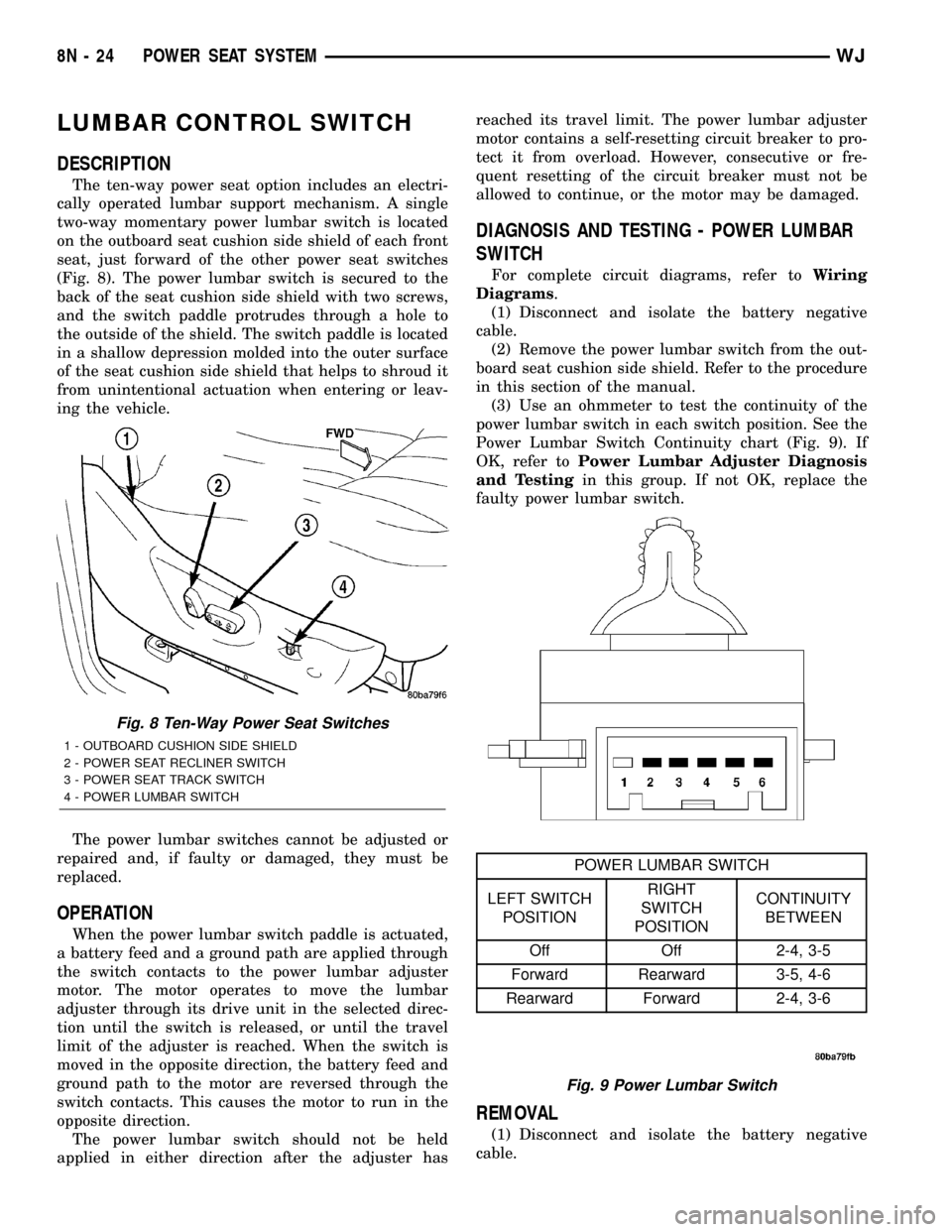
LUMBAR CONTROL SWITCH
DESCRIPTION
The ten-way power seat option includes an electri-
cally operated lumbar support mechanism. A single
two-way momentary power lumbar switch is located
on the outboard seat cushion side shield of each front
seat, just forward of the other power seat switches
(Fig. 8). The power lumbar switch is secured to the
back of the seat cushion side shield with two screws,
and the switch paddle protrudes through a hole to
the outside of the shield. The switch paddle is located
in a shallow depression molded into the outer surface
of the seat cushion side shield that helps to shroud it
from unintentional actuation when entering or leav-
ing the vehicle.
The power lumbar switches cannot be adjusted or
repaired and, if faulty or damaged, they must be
replaced.
OPERATION
When the power lumbar switch paddle is actuated,
a battery feed and a ground path are applied through
the switch contacts to the power lumbar adjuster
motor. The motor operates to move the lumbar
adjuster through its drive unit in the selected direc-
tion until the switch is released, or until the travel
limit of the adjuster is reached. When the switch is
moved in the opposite direction, the battery feed and
ground path to the motor are reversed through the
switch contacts. This causes the motor to run in the
opposite direction.
The power lumbar switch should not be held
applied in either direction after the adjuster hasreached its travel limit. The power lumbar adjuster
motor contains a self-resetting circuit breaker to pro-
tect it from overload. However, consecutive or fre-
quent resetting of the circuit breaker must not be
allowed to continue, or the motor may be damaged.
DIAGNOSIS AND TESTING - POWER LUMBAR
SWITCH
For complete circuit diagrams, refer toWiring
Diagrams.
(1) Disconnect and isolate the battery negative
cable.
(2) Remove the power lumbar switch from the out-
board seat cushion side shield. Refer to the procedure
in this section of the manual.
(3) Use an ohmmeter to test the continuity of the
power lumbar switch in each switch position. See the
Power Lumbar Switch Continuity chart (Fig. 9). If
OK, refer toPower Lumbar Adjuster Diagnosis
and Testingin this group. If not OK, replace the
faulty power lumbar switch.
REMOVAL
(1) Disconnect and isolate the battery negative
cable.
Fig. 8 Ten-Way Power Seat Switches
1 - OUTBOARD CUSHION SIDE SHIELD
2 - POWER SEAT RECLINER SWITCH
3 - POWER SEAT TRACK SWITCH
4 - POWER LUMBAR SWITCH
Fig. 9 Power Lumbar Switch
POWER LUMBAR SWITCH
LEFT SWITCH
POSITIONRIGHT
SWITCH
POSITIONCONTINUITY
BETWEEN
Off Off 2-4, 3-5
Forward Rearward 3-5, 4-6
Rearward Forward 2-4, 3-6
8N - 24 POWER SEAT SYSTEMWJ