timing belt JEEP GRAND CHEROKEE 2002 WJ / 2.G User Guide
[x] Cancel search | Manufacturer: JEEP, Model Year: 2002, Model line: GRAND CHEROKEE, Model: JEEP GRAND CHEROKEE 2002 WJ / 2.GPages: 2199, PDF Size: 76.01 MB
Page 1274 of 2199
REMOVAL
REMOVAL - CAMSHAFT BEARINGS
The camshaft rotates within four steel-shelled,
babbitt-lined bearings that are pressed into the cyl-
inder block and then line reamed. The camshaft
bearing bores and bearing diameters are not the
same size. They are stepped down in 0.254 mm
(0.010 inch) increments from the front bearing (larg-
est) to the rear bearing (smallest). This permits eas-
ier removal and installation of the camshaft. The
camshaft bearings are pressure lubricated. Camshaft
end play is maintained by the thrust plate.
(1) Remove the camshaft (Refer to 9 - ENGINE/
ENGINE BLOCK/CAMSHAFT & BEARINGS (IN
BLOCK) - REMOVAL).
NOTE: It is not advisable to attempt to replace cam-
shaft bearings unless special removal and installa-
tion tools are available, such as recommended tool
8544 Camshaft Bushing Remover Installer.
(2) Using Special tool 8544 Camshaft Bushing
Remover Installer, remove the camshaft bearings.
REMOVAL - CAMSHAFT
WARNING: THE COOLANT IN A RECENTLY OPER-
ATED ENGINE IS HOT AND PRESSURIZED.RELEASE THE PRESSURE BEFORE REMOVING
THE DRAIN COCK, CAP AND DRAIN PLUGS.
(1) Disconnect negative cable from battery.
(2) Drain the cooling system (Refer to 7 - COOL-
ING - STANDARD PROCEDURE).
(3) Remove the radiator (Refer to 7 - COOLING/
ENGINE/RADIATOR - REMOVAL) and condenser
(Refer to 24 - HEATING & AIR CONDITIONING/
PLUMBING/A/C CONDENSER - REMOVAL), if
equipped with A/C.
(4) Remove the engine cylinder head cover (Refer
to 9 - ENGINE/CYLINDER HEAD/CYLINDER
HEAD COVER(S) - REMOVAL).
(5) Remove the rocker arms, bridges and pivots
(Refer to 9 - ENGINE/CYLINDER HEAD/ROCKER
ARM / ADJUSTER ASSY - REMOVAL).
(6) Remove the push rods.
(7) Remove the engine cylinder head and gasket
(Refer to 9 - ENGINE/CYLINDER HEAD - REMOV-
AL).
(8) Remove the hydraulic valve tappets from the
engine cylinder block (Refer to 9 - ENGINE/ENGINE
BLOCK/HYDRAULIC LIFTERS (CAM IN BLOCK) -
REMOVAL).
(9) Remove the vibration damper (Refer to 9 -
ENGINE/ENGINE BLOCK/VIBRATION DAMPER -
REMOVAL).
(10) Remove the timing case cover (Refer to 9 -
ENGINE/VALVE TIMING/TIMING BELT / CHAIN
COVER(S) - REMOVAL).
(11) Rotate the crankshaft until the crankshaft
sprocket timing mark is aligned on centerline with
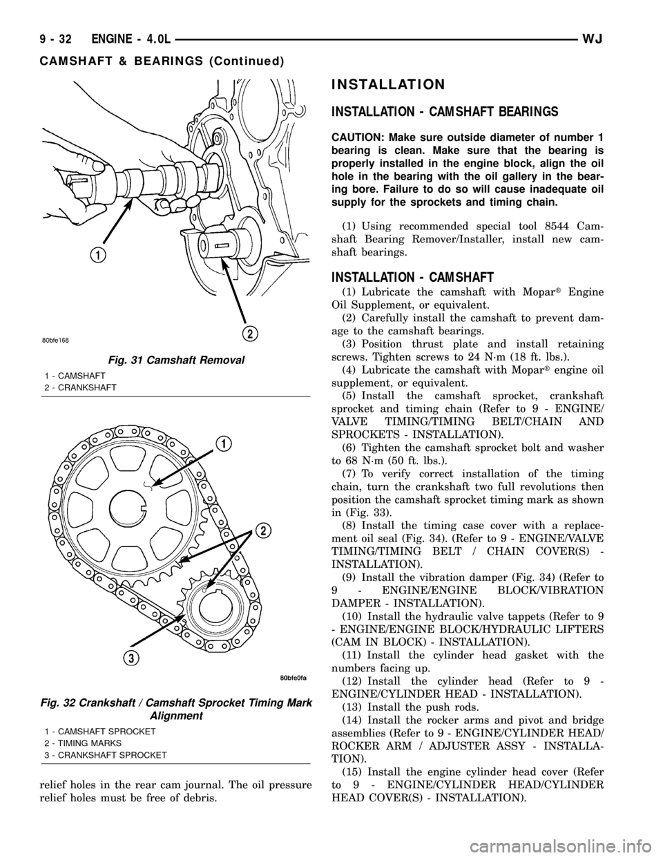
the camshaft sprocket timing mark (Fig. 32).
(12) Remove the timing chain and sprockets (Refer
to 9 - ENGINE/VALVE TIMING/TIMING BELT/
CHAIN AND SPROCKETS - REMOVAL).
(13) Remove the front bumper and/or grille, as
required.
(14) Remove the two thrust plate retaining screws,
thrust plate and camshaft (Fig. 31).
INSPECTION
INSPECTION - CAMSHAFT BEARINGS
(1) Inspect the bearing journals for uneven wear
pattern or finish.
(2) Inspect the bearings for wear.
INSPECTION - CAMSHAFT
(1) Inspect the cam lobes for wear.
(2) Inspect the camshaft position sensor drive gear
for wear.
(3) If the camshaft appears to have been rubbing
against the thrust washer, examine the oil pressure
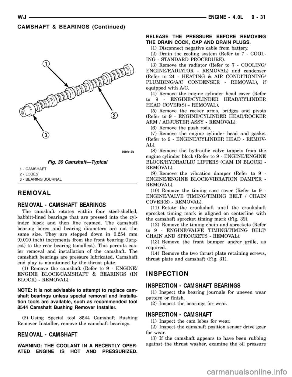
Fig. 30 CamshaftÐTypical
1 - CAMSHAFT
2 - LOBES
3 - BEARING JOURNAL
WJENGINE - 4.0L 9 - 31
CAMSHAFT & BEARINGS (Continued)
Page 1275 of 2199
relief holes in the rear cam journal. The oil pressure
relief holes must be free of debris.
INSTALLATION
INSTALLATION - CAMSHAFT BEARINGS
CAUTION: Make sure outside diameter of number 1
bearing is clean. Make sure that the bearing is
properly installed in the engine block, align the oil
hole in the bearing with the oil gallery in the bear-
ing bore. Failure to do so will cause inadequate oil
supply for the sprockets and timing chain.
(1) Using recommended special tool 8544 Cam-
shaft Bearing Remover/Installer, install new cam-
shaft bearings.
INSTALLATION - CAMSHAFT
(1) Lubricate the camshaft with MopartEngine
Oil Supplement, or equivalent.
(2) Carefully install the camshaft to prevent dam-
age to the camshaft bearings.
(3) Position thrust plate and install retaining
screws. Tighten screws to 24 N´m (18 ft. lbs.).
(4) Lubricate the camshaft with Mopartengine oil
supplement, or equivalent.
(5) Install the camshaft sprocket, crankshaft
sprocket and timing chain (Refer to 9 - ENGINE/
VALVE TIMING/TIMING BELT/CHAIN AND
SPROCKETS - INSTALLATION).
(6) Tighten the camshaft sprocket bolt and washer
to 68 N´m (50 ft. lbs.).
(7) To verify correct installation of the timing
chain, turn the crankshaft two full revolutions then
position the camshaft sprocket timing mark as shown
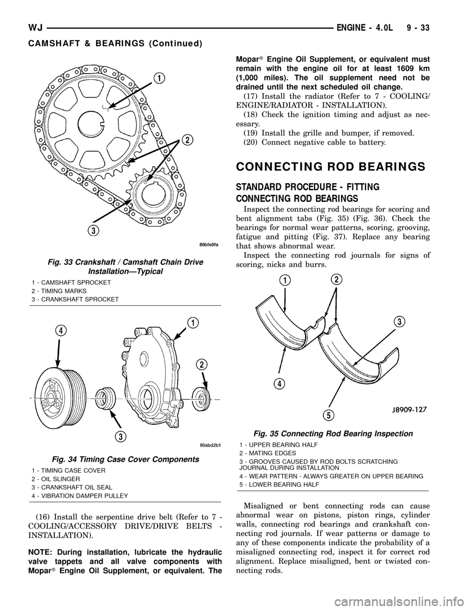
in (Fig. 33).
(8) Install the timing case cover with a replace-
ment oil seal (Fig. 34). (Refer to 9 - ENGINE/VALVE
TIMING/TIMING BELT / CHAIN COVER(S) -
INSTALLATION).
(9) Install the vibration damper (Fig. 34) (Refer to
9 - ENGINE/ENGINE BLOCK/VIBRATION
DAMPER - INSTALLATION).
(10) Install the hydraulic valve tappets (Refer to 9
- ENGINE/ENGINE BLOCK/HYDRAULIC LIFTERS
(CAM IN BLOCK) - INSTALLATION).
(11) Install the cylinder head gasket with the
numbers facing up.
(12) Install the cylinder head (Refer to 9 -
ENGINE/CYLINDER HEAD - INSTALLATION).
(13) Install the push rods.
(14) Install the rocker arms and pivot and bridge
assemblies (Refer to 9 - ENGINE/CYLINDER HEAD/
ROCKER ARM / ADJUSTER ASSY - INSTALLA-
TION).
(15) Install the engine cylinder head cover (Refer
to 9 - ENGINE/CYLINDER HEAD/CYLINDER
HEAD COVER(S) - INSTALLATION).
Fig. 31 Camshaft Removal
1 - CAMSHAFT
2 - CRANKSHAFT
Fig. 32 Crankshaft / Camshaft Sprocket Timing Mark
Alignment
1 - CAMSHAFT SPROCKET
2 - TIMING MARKS
3 - CRANKSHAFT SPROCKET
9 - 32 ENGINE - 4.0LWJ
CAMSHAFT & BEARINGS (Continued)
Page 1276 of 2199
(16) Install the serpentine drive belt (Refer to 7 -
COOLING/ACCESSORY DRIVE/DRIVE BELTS -
INSTALLATION).
NOTE: During installation, lubricate the hydraulic
valve tappets and all valve components with
MoparTEngine Oil Supplement, or equivalent. TheMoparTEngine Oil Supplement, or equivalent must
remain with the engine oil for at least 1609 km
(1,000 miles). The oil supplement need not be
drained until the next scheduled oil change.
(17) Install the radiator (Refer to 7 - COOLING/
ENGINE/RADIATOR - INSTALLATION).
(18) Check the ignition timing and adjust as nec-
essary.
(19) Install the grille and bumper, if removed.
(20) Connect negative cable to battery.
CONNECTING ROD BEARINGS
STANDARD PROCEDURE - FITTING
CONNECTING ROD BEARINGS
Inspect the connecting rod bearings for scoring and
bent alignment tabs (Fig. 35) (Fig. 36). Check the
bearings for normal wear patterns, scoring, grooving,
fatigue and pitting (Fig. 37). Replace any bearing
that shows abnormal wear.
Inspect the connecting rod journals for signs of
scoring, nicks and burrs.
Misaligned or bent connecting rods can cause
abnormal wear on pistons, piston rings, cylinder
walls, connecting rod bearings and crankshaft con-
necting rod journals. If wear patterns or damage to
any of these components indicate the probability of a
misaligned connecting rod, inspect it for correct rod
alignment. Replace misaligned, bent or twisted con-
necting rods.
Fig. 33 Crankshaft / Camshaft Chain Drive
InstallationÐTypical
1 - CAMSHAFT SPROCKET
2 - TIMING MARKS
3 - CRANKSHAFT SPROCKET
Fig. 34 Timing Case Cover Components
1 - TIMING CASE COVER
2 - OIL SLINGER
3 - CRANKSHAFT OIL SEAL
4 - VIBRATION DAMPER PULLEY
Fig. 35 Connecting Rod Bearing Inspection
1 - UPPER BEARING HALF
2 - MATING EDGES
3 - GROOVES CAUSED BY ROD BOLTS SCRATCHING
JOURNAL DURING INSTALLATION
4 - WEAR PATTERN - ALWAYS GREATER ON UPPER BEARING
5 - LOWER BEARING HALF
WJENGINE - 4.0L 9 - 33
CAMSHAFT & BEARINGS (Continued)
Page 1284 of 2199
(e) If end play is not within specification, inspect
crankshaft thrust faces for wear. If no wear is
apparent, replace the thrust bearing and measure
end play. If end play is still not within specifica-
tion, replace the crankshaft.
(11) If the crankshaft was removed, install the
crankshaft into the cylinder block.
(12) Install main bearing cap brace tighten nuts to
47 N´m (35 ft. lbs.) torque.
(13) Install oil pump assy. and tighten attaching
bolts to 23 N´m (17 ft. lbs.)
(14) Install the oil pan (Refer to 9 - ENGINE/LU-
BRICATION/OIL PAN - INSTALLATION).
(15) Install the drain plug. Tighten the plug to 34
N´m (25 ft. lbs.) torque.
(16) Lower the vehicle.
(17) Install the spark plugs. Tighten the plugs to
37 N´m (27 ft. lbs.) torque.
(18) Fill the oil pan with engine oil to the full
mark on the dipstick level.
(19) Connect negative cable to battery.
CRANKSHAFT OIL SEAL -
FRONT
REMOVAL
This procedure is done with the timing case cover
installed.
(1) Disconnect negative cable from battery.
(2) Remove the serpentine drive belt (Refer to 7 -
COOLING/ACCESSORY DRIVE/DRIVE BELTS -
REMOVAL).(3) Remove the vibration damper (Refer to 9 -
ENGINE/ENGINE BLOCK/VIBRATION DAMPER -
REMOVAL).
(4) Remove the radiator shroud.
(5) Carefully remove the oil seal. Make sure seal
bore is clean.
INSTALLATION
This procedure is done with the timing case cover
installed.
(1) Position the replacement oil seal on Timing
Case Cover Alignment and Seal Installation Tool
6139 with seal open end facing inward. Apply a light
film of Perfect Seal, or equivalent, on the outside
diameter of the seal. Lightly coat the crankshaft with
engine oil.
(2) Position the tool and seal over the end of the
crankshaft and insert a draw screw tool into Seal
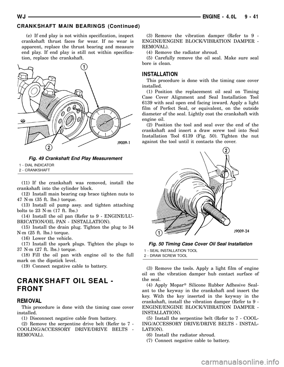
Installation Tool 6139 (Fig. 50). Tighten the nut
against the tool until it contacts the cover.
(3) Remove the tools. Apply a light film of engine
oil on the vibration damper hub contact surface of
the seal.
(4) Apply MopartSilicone Rubber Adhesive Seal-
ant to the keyway in the crankshaft and insert the
key. With the key inserted in the keyway in the
crankshaft, install the vibration damper (Refer to 9 -
ENGINE/ENGINE BLOCK/VIBRATION DAMPER -
INSTALLATION).
(5) Install the serpentine belt (Refer to 7 - COOL-
ING/ACCESSORY DRIVE/DRIVE BELTS - INSTAL-
LATION).
(6) Install the radiator shroud.
(7) Connect negative cable to battery.
Fig. 49 Crankshaft End Play Measurement
1 - DIAL INDICATOR
2 - CRANKSHAFT
Fig. 50 Timing Case Cover Oil Seal Installation
1 - SEAL INSTALLATION TOOL
2 - DRAW SCREW TOOL
WJENGINE - 4.0L 9 - 41
CRANKSHAFT MAIN BEARINGS (Continued)
Page 1301 of 2199
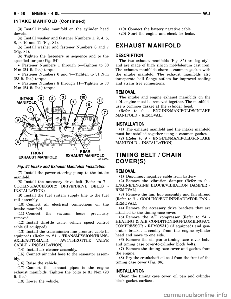
(3) Install intake manifold on the cylinder head
dowels.
(4) Install washer and fastener Numbers 1, 2, 4, 5,
8, 9, 10 and 11 (Fig. 84).
(5) Install washer and fastener Numbers 6 and 7
(Fig. 84).
(6) Tighten the fasteners in sequence and to the
specified torque (Fig. 84).
²Fastener Numbers 1 through 5ÐTighten to 33
N´m (24 ft. lbs.) torque.
²Fastener Numbers 6 and 7ÐTighten to 31 N´m
(23 ft. lbs.) torque.
²Fastener Numbers 8 through 11ÐTighten to 33
N´m (24 ft. lbs.) torque.
(7) Install the power steering pump to the intake
manifold.
(8) Install the accessory drive belt (Refer to 7 -
COOLING/ACCESSORY DRIVE/DRIVE BELTS -
INSTALLATION).
(9) Install the fuel system supply line to the fuel
rail assembly.
(10) Connect all electrical connections on the
intake manifold.
(11) Connect the vacuum hoses previously
removed.
(12) Install throttle cable, vehicle speed control
cable (if equipped).
(13) Install the transmission line pressure cable (if
equipped) (Refer to 21 - TRANSMISSION/TRANS-
AXLE/AUTOMATIC - AW4/THROTTLE VALVE
CABLE - INSTALLATION).
(14) Install air cleaner assembly.
(15) Connect air inlet hose to the resonator assem-
bly.
(16) Raise the vehicle.
(17) Connect the exhaust pipes to the engine
exhaust manifolds. Tighten the bolts to 31 N´m (23
ft. lbs.)
(18) Lower the vehicle.(19) Connect the battery negative cable.
(20) Start the engine and check for leaks.
EXHAUST MANIFOLD
DESCRIPTION
The two exhaust manifolds (Fig. 85) are log style
and are made of high silicon molybdenum cast iron.
The exhaust manifolds share a common gasket with
the intake manifold. The exhaust manifolds also
incorporate ball flange outlets for improved sealing
and strain free connections.
REMOVAL
The intake and engine exhaust manifolds on the
4.0L engine must be removed together. The manifolds
use a common gasket at the cylinder head.
(Refer to 9 - ENGINE/MANIFOLDS/INTAKE
MANIFOLD - REMOVAL).
INSTALLATION
(1) The exhaust manifold and the intake manifold
must be installed together using a common gasket.
(2) (Refer to 9 - ENGINE/MANIFOLDS/INTAKE
MANIFOLD - INSTALLATION).
TIMING BELT / CHAIN
COVER(S)
REMOVAL
(1) Disconnect negative cable from battery.
(2) Remove the vibration damper (Refer to 9 -
ENGINE/ENGINE BLOCK/VIBRATION DAMPER -
REMOVAL).
(3) Remove the fan, hub assembly and fan shroud
(Refer to 7 - COOLING/ENGINE/RADIATOR FAN -
REMOVAL).
(4) Remove the accessory drive brackets that are
attached to the timing case cover.
(5) Remove the A/C compressor (Refer to 24 -
HEATING & AIR CONDITIONING/PLUMBING/A/C
COMPRESSOR - REMOVAL) (if equipped) and gen-
erator bracket assembly from the engine cylinder
head and move to one side.
(6) Remove the oil pan-to-timing case cover bolts
and timing case cover-to-cylinder block bolts.
(7) Remove the timing case cover and gasket from
the engine.
(8) Pry the crankshaft oil seal from the front of the
timing case cover (Fig. 86).
INSTALLATION
Clean the timing case cover, oil pan and cylinder
block gasket surfaces.
Fig. 84 Intake and Exhaust Manifolds Installation
9 - 58 ENGINE - 4.0LWJ
INTAKE MANIFOLD (Continued)
Page 1302 of 2199
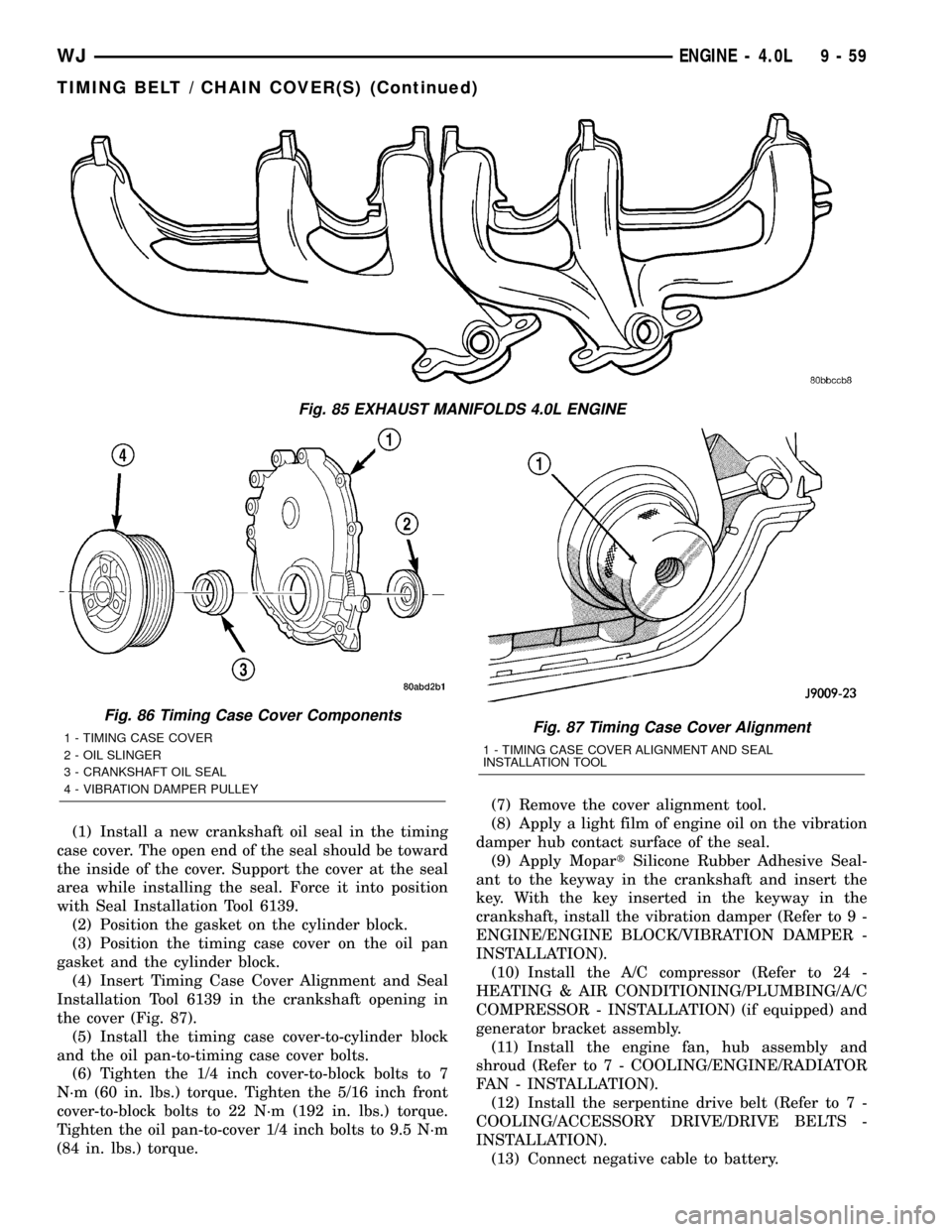
(1) Install a new crankshaft oil seal in the timing
case cover. The open end of the seal should be toward
the inside of the cover. Support the cover at the seal
area while installing the seal. Force it into position
with Seal Installation Tool 6139.
(2) Position the gasket on the cylinder block.
(3) Position the timing case cover on the oil pan
gasket and the cylinder block.
(4) Insert Timing Case Cover Alignment and Seal
Installation Tool 6139 in the crankshaft opening in
the cover (Fig. 87).
(5) Install the timing case cover-to-cylinder block
and the oil pan-to-timing case cover bolts.
(6) Tighten the 1/4 inch cover-to-block bolts to 7
N´m (60 in. lbs.) torque. Tighten the 5/16 inch front
cover-to-block bolts to 22 N´m (192 in. lbs.) torque.
Tighten the oil pan-to-cover 1/4 inch bolts to 9.5 N´m
(84 in. lbs.) torque.(7) Remove the cover alignment tool.
(8) Apply a light film of engine oil on the vibration
damper hub contact surface of the seal.
(9) Apply MopartSilicone Rubber Adhesive Seal-
ant to the keyway in the crankshaft and insert the
key. With the key inserted in the keyway in the
crankshaft, install the vibration damper (Refer to 9 -
ENGINE/ENGINE BLOCK/VIBRATION DAMPER -
INSTALLATION).
(10) Install the A/C compressor (Refer to 24 -
HEATING & AIR CONDITIONING/PLUMBING/A/C
COMPRESSOR - INSTALLATION) (if equipped) and
generator bracket assembly.
(11) Install the engine fan, hub assembly and
shroud (Refer to 7 - COOLING/ENGINE/RADIATOR
FAN - INSTALLATION).
(12) Install the serpentine drive belt (Refer to 7 -
COOLING/ACCESSORY DRIVE/DRIVE BELTS -
INSTALLATION).
(13) Connect negative cable to battery.
Fig. 85 EXHAUST MANIFOLDS 4.0L ENGINE
Fig. 86 Timing Case Cover Components
1 - TIMING CASE COVER
2 - OIL SLINGER
3 - CRANKSHAFT OIL SEAL
4 - VIBRATION DAMPER PULLEYFig. 87 Timing Case Cover Alignment
1 - TIMING CASE COVER ALIGNMENT AND SEAL
INSTALLATION TOOL
WJENGINE - 4.0L 9 - 59
TIMING BELT / CHAIN COVER(S) (Continued)
Page 1303 of 2199
TIMING BELT/CHAIN AND
SPROCKETS
REMOVAL
(1) Disconnect negative cable from battery.
(2) Remove the fan and shroud (Refer to 7 -
COOLING/ENGINE/RADIATOR FAN - REMOVAL).
(3) Remove the serpentine drive belt (Refer to 7 -
COOLING/ACCESSORY DRIVE/DRIVE BELTS -
REMOVAL).
(4) Remove the crankshaft vibration damper (Refer
to 9 - ENGINE/ENGINE BLOCK/VIBRATION
DAMPER - REMOVAL).
(5) Remove the timing case cover (Refer to 9 -
ENGINE/VALVE TIMING/TIMING BELT / CHAIN
COVER(S) - REMOVAL).
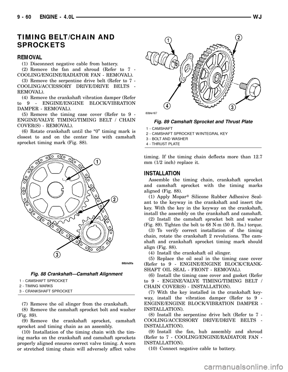
(6) Rotate crankshaft until the ª0º timing mark is
closest to and on the center line with camshaft
sprocket timing mark (Fig. 88).
(7) Remove the oil slinger from the crankshaft.
(8) Remove the camshaft sprocket bolt and washer
(Fig. 89).
(9) Remove the crankshaft sprocket, camshaft
sprocket and timing chain as an assembly.
(10) Installation of the timing chain with the tim-
ing marks on the crankshaft and camshaft sprockets
properly aligned ensures correct valve timing. A worn
or stretched timing chain will adversely affect valvetiming. If the timing chain deflects more than 12.7
mm (1/2 inch) replace it.
INSTALLATION
Assemble the timing chain, crankshaft sprocket
and camshaft sprocket with the timing marks
aligned (Fig. 88).
(1) Apply MopartSilicone Rubber Adhesive Seal-
ant to the keyway in the crankshaft and insert the
key. With the key in the keyway on the crankshaft,
install the assembly on the crankshaft and camshaft.
(2)
Install the camshaft sprocket bolt and washer
(Fig. 89). Tighten the bolt to 68 N´m (50 ft. lbs.) torque.
(3) To verify correct installation of the timing
chain, rotate the crankshaft 2 revolutions. The cam-
shaft and crankshaft sprocket timing mark should
align (Fig. 88).
(4) Install the crankshaft oil slinger.
(5) Replace the oil seal in the timing case cover
(Refer to 9 - ENGINE/ENGINE BLOCK/CRANK-
SHAFT OIL SEAL - FRONT - REMOVAL).
(6) Install the timing case cover and gasket (Refer
to 9 - ENGINE/VALVE TIMING/TIMING BELT /
CHAIN COVER(S) - INSTALLATION).
(7) With the key installed in the crankshaft key-
way, install the vibration damper (Refer to 9 -
ENGINE/ENGINE BLOCK/VIBRATION DAMPER -
INSTALLATION).
(8) Install the serpentine drive belt (Refer to 7 -
COOLING/ACCESSORY DRIVE/DRIVE BELTS -
INSTALLATION).
(9) Install the fan, hub assembly and shroud
(Refer to 7 - COOLING/ENGINE/RADIATOR FAN -
INSTALLATION).
(10) Connect negative cable to battery.
Fig. 88 CrankshaftÐCamshaft Alignment
1 - CAMSHAFT SPROCKET
2 - TIMING MARKS
3 - CRANKSHAFT SPROCKET
Fig. 89 Camshaft Sprocket and Thrust Plate
1 - CAMSHAFT
2 - CAMSHAFT SPROCKET W/INTEGRAL KEY
3 - BOLT AND WASHER
4 - THRUST PLATE
9 - 60 ENGINE - 4.0LWJ
Page 1306 of 2199
VALVE TIMING
DESCRIPTION - TIMING DRIVE SYSTEM....141
OPERATION - TIMING DRIVE SYSTEM.....141
STANDARD PROCEDURE
STANDARD PROCEDURE - ENGINE TIMING
- VERIFICATION.....................141
STANDARD PROCEDUREÐMEASURING
TIMING CHAIN WEAR.................145TIMING BELT / CHAIN COVER(S)
REMOVAL............................146
INSTALLATION........................146
TIMING BELT/CHAIN AND SPROCKETS
REMOVAL............................147
INSPECTION.........................149
INSTALLATION........................149
ENGINE - 4.7L
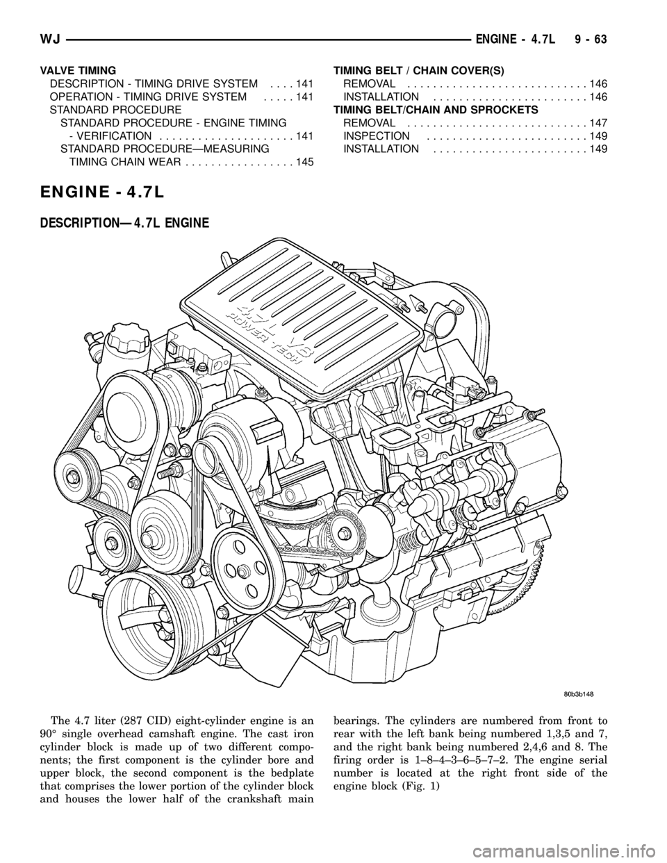
DESCRIPTIONÐ4.7L ENGINE
The 4.7 liter (287 CID) eight-cylinder engine is an
90É single overhead camshaft engine. The cast iron
cylinder block is made up of two different compo-
nents; the first component is the cylinder bore and
upper block, the second component is the bedplate
that comprises the lower portion of the cylinder block
and houses the lower half of the crankshaft mainbearings. The cylinders are numbered from front to
rear with the left bank being numbered 1,3,5 and 7,
and the right bank being numbered 2,4,6 and 8. The
firing order is 1±8±4±3±6±5±7±2. The engine serial
number is located at the right front side of the
engine block (Fig. 1)
WJENGINE - 4.7L 9 - 63
Page 1329 of 2199
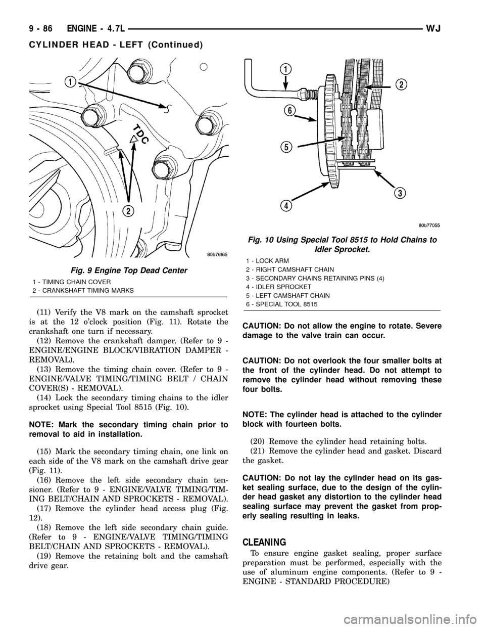
(11) Verify the V8 mark on the camshaft sprocket
is at the 12 o'clock position (Fig. 11). Rotate the
crankshaft one turn if necessary.
(12) Remove the crankshaft damper. (Refer to 9 -
ENGINE/ENGINE BLOCK/VIBRATION DAMPER -
REMOVAL).
(13) Remove the timing chain cover. (Refer to 9 -
ENGINE/VALVE TIMING/TIMING BELT / CHAIN
COVER(S) - REMOVAL).
(14) Lock the secondary timing chains to the idler
sprocket using Special Tool 8515 (Fig. 10).
NOTE: Mark the secondary timing chain prior to
removal to aid in installation.
(15) Mark the secondary timing chain, one link on
each side of the V8 mark on the camshaft drive gear
(Fig. 11).
(16) Remove the left side secondary chain ten-
sioner. (Refer to 9 - ENGINE/VALVE TIMING/TIM-
ING BELT/CHAIN AND SPROCKETS - REMOVAL).
(17) Remove the cylinder head access plug (Fig.
12).
(18) Remove the left side secondary chain guide.
(Refer to 9 - ENGINE/VALVE TIMING/TIMING
BELT/CHAIN AND SPROCKETS - REMOVAL).
(19) Remove the retaining bolt and the camshaft
drive gear.CAUTION: Do not allow the engine to rotate. Severe
damage to the valve train can occur.
CAUTION: Do not overlook the four smaller bolts at
the front of the cylinder head. Do not attempt to
remove the cylinder head without removing these
four bolts.
NOTE: The cylinder head is attached to the cylinder
block with fourteen bolts.
(20) Remove the cylinder head retaining bolts.
(21) Remove the cylinder head and gasket. Discard
the gasket.
CAUTION: Do not lay the cylinder head on its gas-
ket sealing surface, due to the design of the cylin-
der head gasket any distortion to the cylinder head
sealing surface may prevent the gasket from prop-
erly sealing resulting in leaks.
CLEANING
To ensure engine gasket sealing, proper surface
preparation must be performed, especially with the
use of aluminum engine components. (Refer to 9 -
ENGINE - STANDARD PROCEDURE)
Fig. 9 Engine Top Dead Center
1 - TIMING CHAIN COVER
2 - CRANKSHAFT TIMING MARKS
Fig. 10 Using Special Tool 8515 to Hold Chains to
Idler Sprocket.
1 - LOCK ARM
2 - RIGHT CAMSHAFT CHAIN
3 - SECONDARY CHAINS RETAINING PINS (4)
4 - IDLER SPROCKET
5 - LEFT CAMSHAFT CHAIN
6 - SPECIAL TOOL 8515
9 - 86 ENGINE - 4.7LWJ
CYLINDER HEAD - LEFT (Continued)
Page 1331 of 2199
(3) Position the cylinder head onto the cylinder
block. Make sure the cylinder head seats fully over
the locating dowels.
NOTE: The four smaller cylinder head mounting
bolts require sealant to be added to them before
installing. Failure to do so may cause leaks.
(4) Lubricate the cylinder head bolt threads with
clean engine oil and install the ten M11 bolts.
(5) Coat the four M8 cylinder head bolts with
MopartLock and Seal Adhesivethen install the
bolts.
NOTE: The cylinder head bolts are tightened using
an angle torque procedure, however, the bolts are
not a torque-to-yield design.
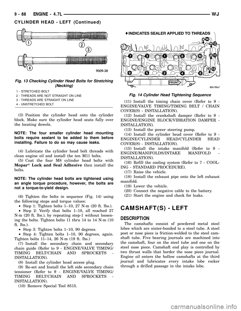
(6) Tighten the bolts in sequence (Fig. 14) using
the following steps and torque values:
²Step 1: Tighten bolts 1±10, 27 N´m (20 ft. lbs.).
²Step 2: Verify that bolts 1±10, all reached 27
N´m (20 ft. lbs.), by repeating step-1 without loosen-
ing the bolts. Tighten bolts 11 thru 14 to 14 N´m (10
ft. lbs.).
²Step 3: Tighten bolts 1±10, 90 degrees.
²Step 4: Tighten bolts 1±10, 90 degrees, again.
Tighten bolts 11±14, 26 N´m (19 ft. lbs.)
(7) Install the secondary chain and secondary
chain guide (Refer to 9 - ENGINE/VALVE TIMING/
TIMING BELT/CHAIN AND SPROCKETS -
INSTALLATION).
(8) Install the cylinder head access plug.
(9) Re-set and Install the left side secondary chain
tensioner (Refer to 9 - ENGINE/VALVE TIMING/
TIMING BELT/CHAIN AND SPROCKETS -
INSTALLATION).
(10) Remove Special Tool 8515.(11) Install the timing chain cover (Refer to 9 -
ENGINE/VALVE TIMING/TIMING BELT / CHAIN
COVER(S) - INSTALLATION).
(12) Install the crankshaft damper (Refer to 9 -
ENGINE/ENGINE BLOCK/VIBRATION DAMPER -
INSTALLATION).
(13) Install the power steering pump.
(14) Install the cylinder head cover (Refer to 9 -
ENGINE/CYLINDER HEAD/CYLINDER HEAD
COVER(S) - INSTALLATION).
(15) Install the intake manifold (Refer to 9 -
ENGINE/MANIFOLDS/INTAKE MANIFOLD -
INSTALLATION).
(16) Refill the cooling system (Refer to 7 - COOL-
ING - STANDARD PROCEDURE).
(17) Raise the vehicle.
(18) Install the exhaust pipe onto the left exhaust
manifold.
(19) Lower the vehicle.
(20) Connect the negative cable to the battery.
(21) Start the engine and check for leaks.
CAMSHAFT(S) - LEFT
DESCRIPTION
The camshafts consist of powdered metal steel
lobes which are sinter-bonded to a steel tube. A steel
post or nose piece is friction-welded to the steel cam-
shaft tube. Five bearing journals are machined into
the camshaft, four on the steel tube and one on the
steel nose piece. Camshaft end play is controlled by
two thrust walls that border the nose piece journal.
Engine oil enters the hollow camshafts at the third
journal and lubricates every intake lobe rocker
through a drilled passage in the intake lobe.
Fig. 13 Checking Cylinder Head Bolts for Stretching
(Necking)
1 - STRETCHED BOLT
2 - THREADS ARE NOT STRAIGHT ON LINE
3 - THREADS ARE STRAIGHT ON LINE
4 - UNSTRETCHED BOLTFig. 14 Cylinder Head Tightening Sequence
9 - 88 ENGINE - 4.7LWJ
CYLINDER HEAD - LEFT (Continued)