Bus JEEP GRAND CHEROKEE 2002 WJ / 2.G Workshop Manual
[x] Cancel search | Manufacturer: JEEP, Model Year: 2002, Model line: GRAND CHEROKEE, Model: JEEP GRAND CHEROKEE 2002 WJ / 2.GPages: 2199, PDF Size: 76.01 MB
Page 1834 of 2199

TRANSFER CASE - NV247
TABLE OF CONTENTS
page page
TRANSFER CASE - NV247
DESCRIPTION........................315
OPERATION..........................316
DIAGNOSIS AND TESTING - TRANSFER
CASE - NV247.......................316
REMOVAL............................317
DISASSEMBLY........................317
CLEANING...........................324
INSPECTION.........................324
ASSEMBLY...........................326
INSTALLATION........................335
SPECIFICATIONS
TRANSFER CASE - NV247.............336
SPECIAL TOOLS
TRANSFER CASE - NV247.............337FLUID
STANDARD PROCEDURE - FLUID DRAIN/
REFILL............................338
FRONT OUTPUT SHAFT SEAL
REMOVAL............................338
INSTALLATION........................338
REAR RETAINER BUSHING AND SEAL
REMOVAL............................339
INSTALLATION........................339
SHIFT CABLE
REMOVAL............................340
INSTALLATION........................340
TRANSFER CASE - NV247
DESCRIPTION
The NV247 (Fig. 1) is an on-demand 4-wheel drive
transfer case with two operating ranges and a neu-
tral position. Operating ranges are 4-high and 4-low.
The 4-low range is used for extra pulling power in
off-road situations.
TRANSFER CASE IDENTIFICATION
A circular I.D. tag is attached to the rear case of
each NV247 transfer case (Fig. 2). The tag indicates
the following information:
²Model number
²Serial number
²Assembly number
²Gear ratio
²Location of manufacture
The transfer case serial number also represents
the date of build.
Fig. 1 NV247 Transfer Case
Fig. 2 Transfer Case I.D. Tag
1 - FILL PLUG
2 - I.D. TAG
3 - DRAIN PLUG
WJTRANSFER CASE - NV247 21 - 315
Page 1841 of 2199

(7) Remove range clutch sleeve, blockout spring,
locking clutch, and locking clutch spring from main-
shaft (Fig. 20).
(8) Remove shift sector. Rotate and tilt sector as
needed to remove it (Fig. 21).
(9) Remove shift sector bushing and O-ring (Fig.
22).
INPUT GEAR/LOW RANGE ASSEMBLY
(1) Turn front case on side so front bearing
retainer is accessible.
(2) Remove front bearing retainer bolts (Fig. 23).
(3) Remove front bearing retainer as follows:(a) Loosen retainer with flat blade screwdriver
to break sealer bead.To avoid damaging case
and retainer, position screwdriver blade only
in slots provided in retainer (Fig. 24).
(b) Then remove retainer from case and gear.
Fig. 20 Range Clutch Sleeve, Blockout Spring,
Locking Clutch and Spring
1 - LOCKING CLUTCH SPRING
2 - BLOCKOUT SPRING
3 - SNAP-RING
4 - RANGE CLUTCH SLEEVE
5 - LOCKING CLUTCH
6 - DRIVE SPROCKET HUB
Fig. 21 Shift Sector Removal
1 - SHIFT SECTOR
Fig. 22 Sector Bushing And O-Ring Removal
1 - SHIFT SECTOR BUSHING
2 - O-RING
Fig. 23 Front Bearing Retainer Bolt Removal
1 - FRONT BEARING RETAINER
21 - 322 TRANSFER CASE - NV247WJ
TRANSFER CASE - NV247 (Continued)
Page 1844 of 2199

INPUT AND LOW RANGE GEARS
Inspect the low range gear pinions and pinion pins.
Replace the low range gear if any of the pins or pin-
ions are worn or damaged.
Inspect the thrust washers, retainer, and snap-
ring. Replace the snap-ring if bent, or distorted.
Replace the thrust washers and retainer if worn,
cracked or damaged in any way.
Examine the input gear carefully. Be sure the gear
teeth and bearing surfaces are in good condition.
Replace the gear if wear or damage is evident.
Check the input gear pilot bearing. Rotate the
bearing and check for roughness or noise. Also check
bearing position in the bore. The bearing should be
recessed approximately 2.5 mm (0.100 in.) below the
top edge of the bore. The bearing should not be
seated at the bottom of the bore. Replace the bearing
if worn, or roughness is evident. Replace both the
gear and bearing if the bearing is a loose fit in the
bore.
GEAR CASE AND RETAINERS
Examine both case halves and retainers carefully.
Replace any retainer or case half if wear, cracks, or
other damage is evident.
Check condition of the low range annulus gear and
the shift rail bushing in the front case (Fig. 32). The
low range annulus gear is not a serviceable part.
Replace the gear and case as an assembly if the gear
is loose, worn, or damaged. The shift rail bushing is
a serviceable part and can be replaced if necessary.
Check the bushing in the rear retainer. Replace the
bushing if worn or scored.
Examine the sealing surfaces of both case halves
and retainers. Small burrs, or scratches on these sur-
faces can be reduced with crocus cloth or a fine tooth
file.
Examine condition of the shift rail bushing in the
front case. If the bushing is worn or damaged, it can
be removed with a blind hole type puller. A replace-
ment bushing can be installed with a suitable size
driver. Recess the bushing slightly below the edge of
the bore but do not seat it all the into the case.
GEARTRAIN
Inspect the mainshaft splines, gear teeth and bear-
ing surfaces carefully for evidence of wear, or dam-
age. Replace the shaft if necessary. do not attempt to
salvage it if damaged.
The shift rail and range fork are an assembly.
Replace both parts if either is damaged. However, the
nylon pads in the fork can be replaced if worn, or
cracked.
Inspect the transfer case snap-rings closely. Do not
attempt to salvage a distorted snap-ring by straight-ening or reshaping it. Replace any snap-ring that is
distorted, or worn.
Inspect the low range gear, input gear and the gear
thrust washers retainer, and snap-ring. The low
range gear is serviced as an assembly only. Replace
the gear if the case or pinions are damaged.
During inspection, also make sure the seal surface
of the input gear is in good condition. Minor nicks on
this surface can be reduced with crocus cloth. How-
ever, replace the gear if the seal surface is severely
scored or worn.
OIL PUMP AND PROGRESSIVE COUPLING
The oil pump and progressive coupling are not ser-
viceable components. Replace the coupling as an
assembly if it is damaged. Replace the oil pump as
an assembly if the gear teeth are worn, or if the
pump has become damaged.
BEARINGS AND SEALS
The transfer case seals should be replaced during
overhaul. Use new seals in the input gear bearing
retainer, front case and rear retainer. Also replace
the yoke seal washer and the detent plug O-ring.
Check condition of each transfer case bearing.
Replace any bearing exhibiting signs of roughness,
wear, or damage.
Fig. 32 Low Range Annulus Gear Location
1 - LOW RANGE ANNULUS GEAR
2 - SHIFT RAIL BUSHING
WJTRANSFER CASE - NV247 21 - 325
TRANSFER CASE - NV247 (Continued)
Page 1849 of 2199

(7) Install snap-ring to hold input/low range gear
into front bearing (Fig. 47).
(8) Clean gasket sealer residue from retainer and
inspect retainer for cracks or other damage.
(9) Applya3mm(1/8 in.) bead of Mopartgasket
maker or silicone adhesive to sealing surface of
retainer.
(10) Align cavity in seal retainer with fluid return
hole in front of case.
CAUTION: Do not block fluid return cavity on seal-
ing surface of retainer when applying MoparTgas-
ket maker or silicone adhesive sealer. Seal failure
and fluid leak can result.
(11) Install bolts to hold retainer to transfer case
(Fig. 48). Tighten to 21 N´m (16 ft. lbs.) of torque.SHIFT FORKS AND MAINSHAFT
(1) Install new sector shaft O-ring and bushing
(Fig. 49).
(2) Install shift sector (Fig. 50).
(3) Install locking clutch spring, locking clutch,
blockout spring, and range clutch sleeve, to main-
shaft as shown in (Fig. 51). Install snap ring.
(4) Install drive sprocket hub to mainshaft and
manually load the needle bearings.
(5) Install new pads on range fork, if necessary.
Fig. 47 Install Input Gear Snap-Ring
1 - INPUT GEAR
2 - SNAP-RING
Fig. 48 Install Front Bearing Retainer
1 - FRONT BEARING RETAINER
Fig. 49 Sector O-Ring And Bushing Installation
1 - SECTOR BUSHING
2 - O-RING
Fig. 50 Shift Sector Installation
1 - SHIFT SECTOR
21 - 330 TRANSFER CASE - NV247WJ
TRANSFER CASE - NV247 (Continued)
Page 1856 of 2199

SPECIAL TOOLS
TRANSFER CASE - NV247
Installer, Bearing - 5066
Installer, Seal - 6952-A
Installer, Bearing - 6953
Remover, Bushing - 6957
Installer, Seal - C-3995-A
Handle - C-4171
Installer, Bushing - 8145
Remover, Bearing - C-4210
Remover, Bearing - L-4454
Cup - 8148
WJTRANSFER CASE - NV247 21 - 337
TRANSFER CASE - NV247 (Continued)
Page 1858 of 2199

REAR RETAINER BUSHING
AND SEAL
REMOVAL
(1) Raise vehicle on hoist.
(2) Remove rear propeller shaft. (Refer to 3 - DIF-
FERENTIAL & DRIVELINE/PROPELLER SHAFT/
PROPELLER SHAFT - REMOVAL)
(3) Using a suitable pry tool or slide-hammer
mounted screw, remove the rear retainer seal.
(4) Using Remover 6957, remove bushing from
rear retainer (Fig. 75).
INSTALLATION
(1) Clean fluid residue from sealing surface and
inspect for defects.
(2) Position replacement bushing in rear retainer
with fluid port in bushing aligned with slot in
retainer.
(3) Using Installer 8145, drive bushing into
retainer until installer seats against case (Fig. 76).
(4) Using Installer C-3995-A, install seal in rear
retainer (Fig. 77).
(5) Install rear propeller shaft. (Refer to 3 - DIF-
FERENTIAL & DRIVELINE/PROPELLER SHAFT/
PROPELLER SHAFT - INSTALLATION)
(6) Verify proper fluid level.
(7) Lower vehicle.
Fig. 74 Front Output Seal Installation
1 - INSTALLER 6952-A
2 - TRANSFER CASE
Fig. 75 Rear Retainer Bushing Removal
1 - REMOVER 6957
2 - REAR RETAINER BUSHING
Fig. 76 Rear Retainer Bushing Installation
1 - REAR RETAINER BUSHING
2 - INSTALLER 8145
Fig. 77 Install Rear Retainer Seal
1 - SPECIAL TOOL C-4171
2 - SPECIAL TOOL C-3995-A
WJTRANSFER CASE - NV247 21 - 339
FRONT OUTPUT SHAFT SEAL (Continued)
Page 1876 of 2199

(2) Apply silicone lubricant to a cloth and wipe it
on door seals to avoid over-spray that can soil pas-
senger's clothing.
(3) Before applying lubricant, the component
should be wiped clean. After lubrication, any excess
lubricant should be removed.
(4) The hood latch, latch release mechanism, latch
striker, and safety latch should be lubricated period-
ically.
(5) The door lock cylinders should be lubricated
twice each year (preferably autumn and spring).
(a) Spray a small amount of lock cylinder lubri-
cant directly into the lock cylinder.
(b) Apply a small amount to the key and insert
it into the lock cylinder.
(c) Rotate it to the locked position and then back
to the unlocked position several times.(d) Remove the key. Wipe the lubricant from it
with a clean cloth to avoid soiling of clothing.
STANDARD PROCEDURE - DRILLING AND
WELDING
When holes must be drilled or punched in an inner
body panel, verify depth of space to the outer body
panel, electrical wiring, or other components. Dam-
age to vehicle can result.
Do not weld exterior panels unless combustible
material on the interior of vehicle is removed from
the repair area. Fire or hazardous conditions, can
result.
Always have a fire extinguisher ready for use when
welding.
SPECIFICATIONS
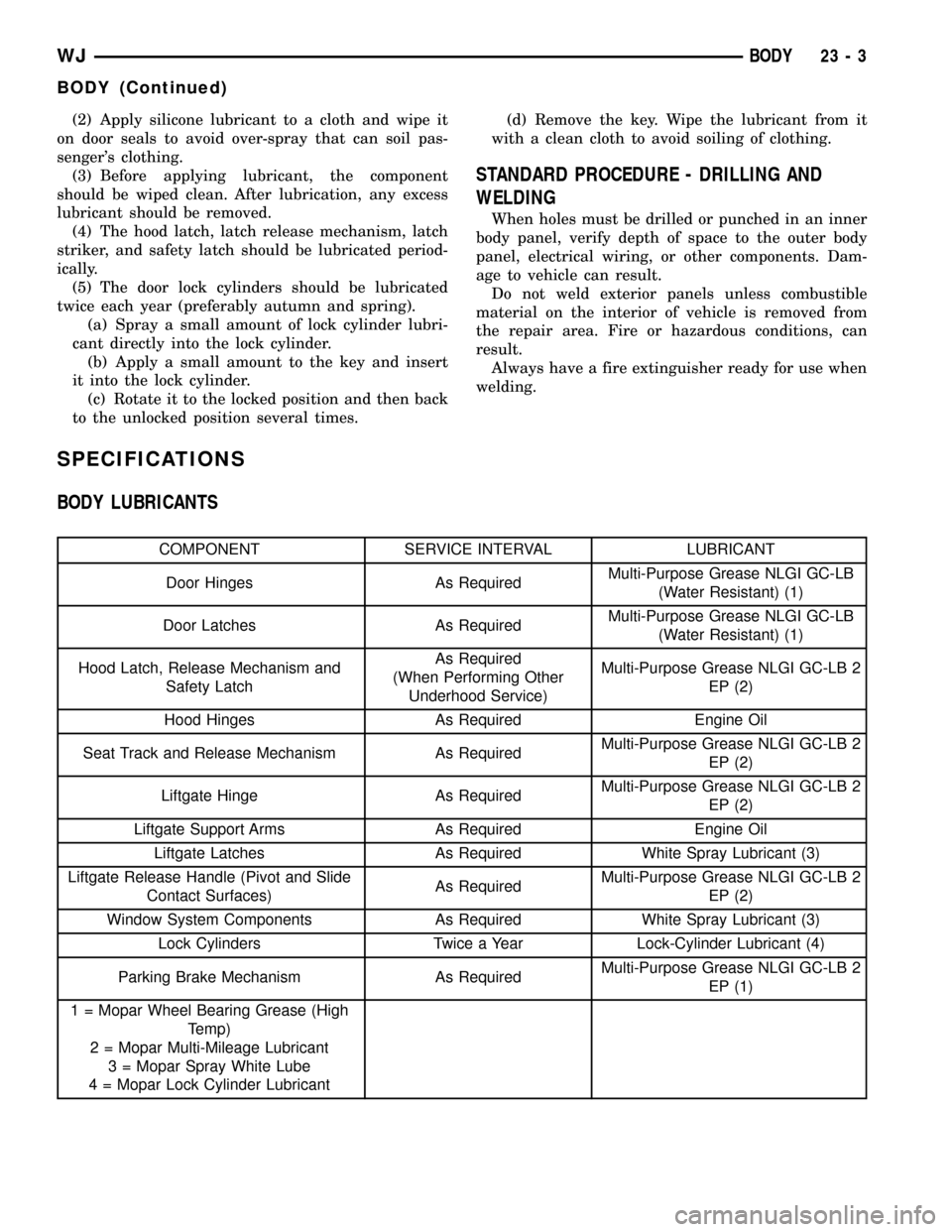
BODY LUBRICANTS
COMPONENT SERVICE INTERVAL LUBRICANT
Door Hinges As RequiredMulti-Purpose Grease NLGI GC-LB
(Water Resistant) (1)
Door Latches As RequiredMulti-Purpose Grease NLGI GC-LB
(Water Resistant) (1)
Hood Latch, Release Mechanism and
Safety LatchAs Required
(When Performing Other
Underhood Service)Multi-Purpose Grease NLGI GC-LB 2
EP (2)
Hood Hinges As Required Engine Oil
Seat Track and Release Mechanism As RequiredMulti-Purpose Grease NLGI GC-LB 2
EP (2)
Liftgate Hinge As RequiredMulti-Purpose Grease NLGI GC-LB 2
EP (2)
Liftgate Support Arms As Required Engine Oil
Liftgate Latches As Required White Spray Lubricant (3)
Liftgate Release Handle (Pivot and Slide
Contact Surfaces)As RequiredMulti-Purpose Grease NLGI GC-LB 2
EP (2)
Window System Components As Required White Spray Lubricant (3)
Lock Cylinders Twice a Year Lock-Cylinder Lubricant (4)
Parking Brake Mechanism As RequiredMulti-Purpose Grease NLGI GC-LB 2
EP (1)
1 = Mopar Wheel Bearing Grease (High
Temp)
2 = Mopar Multi-Mileage Lubricant
3 = Mopar Spray White Lube
4 = Mopar Lock Cylinder Lubricant
WJBODY 23 - 3
BODY (Continued)
Page 2095 of 2199

Both the manual A/C Heater control panel and the
AZC control panel are serviced only as complete
units and cannot be repaired. If faulty or damaged,
the entire control panel unit must be replaced.
DIAGNOSIS AND TESTING - AUTOMATIC ZONE
CONTROL SYSTEM
The Automatic Zone Control (AZC) control module
has a system self-diagnostic mode which continuously
monitors various parameters during normal system
operation. If a system fault is detected, a current and
historical fault is recorded. When the current fault is
cleared, the historical fault remains until reset (man-
ually or automatically). Both the current and histor-
ical fault codes can be accessed through either the
front panel, or over the Programmable Communica-
tions Interface (PCI) bus using a DRBIIItscan tool,
and the appropriate diagnostic information.
The AZC control module is capable of three differ-
ent types of self-diagnostic tests, as follows:
²Fault Code Tests
²Input Circuit Tests
²Output Circuit/Actuator Tests
The information that follows describes:
²How to read the self-diagnostic display
²How to enter the AZC control module self-diag-
nostic test mode
²How to select the self-diagnostic test types
²How to perform the different tests
ENTERING THE AZC SELF-DIAGNOSTIC MODE
To enter the AZC self-diagnostic mode, perform the
following:
(1) Depress the a/c and recirc buttons at the same
time and hold. Rotate the left temperature control
knob clockwise (CW) one detent.
(2) If you continue to keep the a/c and recirc but-
tons depressed, the AZC control module will perform
a Segment Test of the Vacuum Fluorescent (VF) dis-
play. In the Segment Test you should see all of the
display segments illuminate as long as both buttons
are held. If a display segment fails to illuminate, the
vacuum fluorescent display is faulty and the a/c
heater control must be replaced.
(3) After viewing the Segment Test, release the
A/C and Recirc buttons and the display will clear
momentarily.Ifa0isdisplayed, then no faults
are set in the system.Should there be any faults,
either9current9or9historical9, all fault codes will be
displayed in ascending numerical sequence (note no
effort is made to display fault codes in chronological
order). Each fault code is displayed for one second
before the next code is displayed. Once all fault codes
have been displayed, the system will then repeat the
fault code numbers. This will continue until the left
side set temperature control is moved at least onedetent position in the CW direction or the ignition is
turned9OFF9.
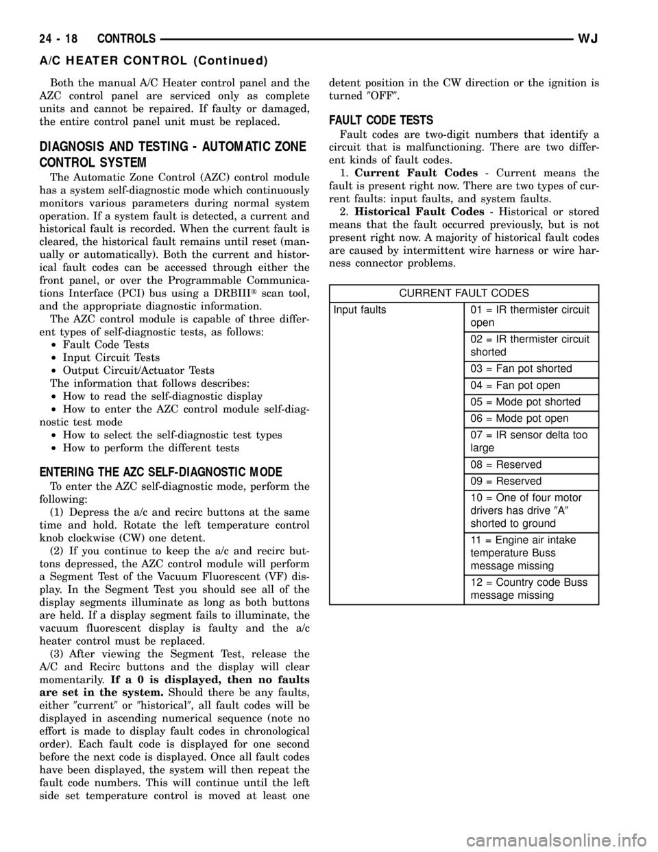
FAULT CODE TESTS
Fault codes are two-digit numbers that identify a
circuit that is malfunctioning. There are two differ-
ent kinds of fault codes.
1.Current Fault Codes- Current means the
fault is present right now. There are two types of cur-
rent faults: input faults, and system faults.
2.Historical Fault Codes- Historical or stored
means that the fault occurred previously, but is not
present right now. A majority of historical fault codes
are caused by intermittent wire harness or wire har-
ness connector problems.
CURRENT FAULT CODES
Input faults 01 = IR thermister circuit
open
02 = IR thermister circuit
shorted
03 = Fan pot shorted
04 = Fan pot open
05 = Mode pot shorted
06 = Mode pot open
07 = IR sensor delta too
large
08 = Reserved
09 = Reserved
10 = One of four motor
drivers has drive9A9
shorted to ground
11 = Engine air intake
temperature Buss
message missing
12 = Country code Buss
message missing
24 - 18 CONTROLSWJ
A/C HEATER CONTROL (Continued)
Page 2096 of 2199

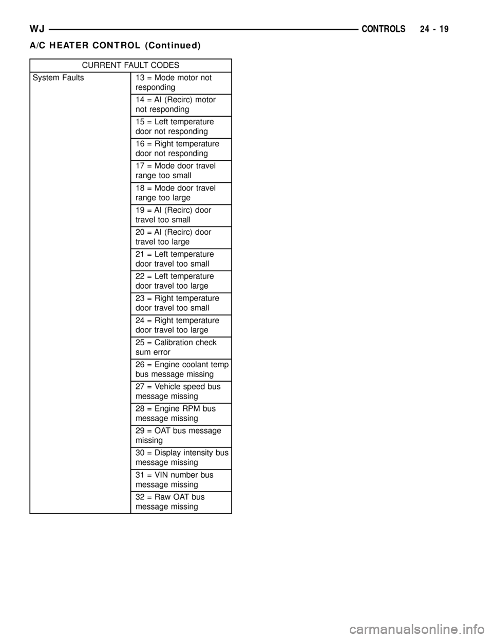
CURRENT FAULT CODES
System Faults 13 = Mode motor not
responding
14 = AI (Recirc) motor
not responding
15 = Left temperature
door not responding
16 = Right temperature
door not responding
17 = Mode door travel
range too small
18 = Mode door travel
range too large
19 = AI (Recirc) door
travel too small
20 = AI (Recirc) door
travel too large
21 = Left temperature
door travel too small
22 = Left temperature
door travel too large
23 = Right temperature
door travel too small
24 = Right temperature
door travel too large
25 = Calibration check
sum error
26 = Engine coolant temp
bus message missing
27 = Vehicle speed bus
message missing
28 = Engine RPM bus
message missing
29 = OAT bus message
missing
30 = Display intensity bus
message missing
31 = VIN number bus
message missing
32 = Raw OAT bus
message missing
WJCONTROLS 24 - 19
A/C HEATER CONTROL (Continued)
Page 2097 of 2199

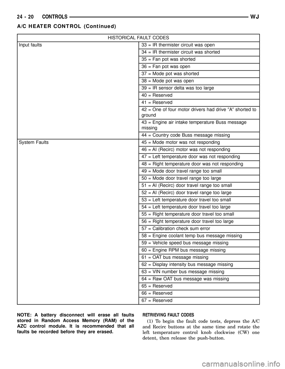
HISTORICAL FAULT CODES
Input faults 33 = IR thermister circuit was open
34 = IR thermister circuit was shorted
35 = Fan pot was shorted
36 = Fan pot was open
37 = Mode pot was shorted
38 = Mode pot was open
39 = IR sensor delta was too large
40 = Reserved
41 = Reserved
42 = One of four motor drivers had drive9A9shorted to
ground
43 = Engine air intake temperature Buss message
missing
44 = Country code Buss message missing
System Faults 45 = Mode motor was not responding
46 = AI (Recirc) motor was not responding
47 = Left temperature door was not responding
48 = Right temperature door was not responding
49 = Mode door travel range too small
50 = Mode door travel range too large
51 = AI (Recirc) door travel range too small
52 = AI (Recirc) door travel range too large
53 = Left temperature door travel too small
54 = Left temperature door travel too large
55 = Right temperature door travel too small
56 = Right temperature door travel too large
57 = Calibration check sum error
58 = Engine coolant temp bus message missing
59 = Vehicle speed bus message missing
60 = Engine RPM bus message missing
61 = OAT bus message missing
62 = Display intensity bus message missing
63 = VIN number bus message missing
64 = Raw OAT bus message was missing
65 = Reserved
66 = Reserved
67 = Reserved
NOTE: A battery disconnect will erase all faults
stored in Random Access Memory (RAM) of the
AZC control module. It is recommended that all
faults be recorded before they are erased.RETRIEVING FAULT CODES
(1) To begin the fault code tests, depress the A/C
and Recirc buttons at the same time and rotate the
left temperature control knob clockwise (CW) one
detent, then release the push-button.
24 - 20 CONTROLSWJ
A/C HEATER CONTROL (Continued)