Color JEEP GRAND CHEROKEE 2002 WJ / 2.G Owner's Manual
[x] Cancel search | Manufacturer: JEEP, Model Year: 2002, Model line: GRAND CHEROKEE, Model: JEEP GRAND CHEROKEE 2002 WJ / 2.GPages: 2199, PDF Size: 76.01 MB
Page 560 of 2199
WARNING: USE EXTREME CARE TO PREVENT ANY
FOREIGN MATERIAL FROM ENTERING THE DRIVER
AIRBAG, OR BECOMING ENTRAPPED BETWEEN
THE DRIVER AIRBAG CUSHION AND THE DRIVER
AIRBAG TRIM COVER. FAILURE TO OBSERVE THIS
WARNING COULD RESULT IN OCCUPANT INJURIES
UPON AIRBAG DEPLOYMENT.
WARNING: THE DRIVER AIRBAG TRIM COVER
MUST NEVER BE PAINTED. REPLACEMENT AIR-
BAGS AND TRIM COVERS ARE SERVICED IN THE
ORIGINAL COLORS. PAINT MAY CHANGE THE WAY
IN WHICH THE MATERIAL OF THE TRIM COVER
RESPONDS TO AN AIRBAG DEPLOYMENT. FAIL-
URE TO OBSERVE THIS WARNING COULD RESULT
IN OCCUPANT INJURIES UPON AIRBAG DEPLOY-
MENT.
(1) Assemble the driver airbag trim cover onto the
airbag housing. (Refer to 8 - ELECTRICAL/RE-
STRAINTS/DRIVER AIRBAG - ASSEMBLY).
(2) Position the driver airbag close enough to the
steering wheel to reconnect all three electrical con-
nections on the back of the airbag housing.
(3) When installing the driver airbag, reconnect
the two clockspring driver airbag pigtail wire connec-
tors to the airbag inflator connector receptacles by
pressing straight in on the connectors (Fig. 19), then
pushing the locks straight into the connectors. You
can be certain that the connector is fully engaged by
listening carefully for a distinct, audible click as the
connector latches snap into place.
(4) Reconnect the steering wheel wire harness con-
nector for the horn switch to the horn switch feed
pigtail wire connector, which is located at the back of
the driver airbag housing.
(5) Carefully position the driver airbag in the
steering wheel. Be certain that the clockspring pig-
tail wires and steering wheel wire harness in the
steering wheel hub area are not pinched between the
driver airbag and the steering wheel armature.
(6) From the underside of the steering wheel,
install and tighten the two screws that secure the
driver airbag to the steering wheel armature.
Tighten the screws to 10 N´m (90 in. lbs.).
(7) Do not reconnect the battery negative cable at
this time. The supplemental restraint system verifi-
cation test procedure should be performed following
service of any supplemental restraint system compo-
nent. (Refer to 8 - ELECTRICAL/RESTRAINTS -
STANDARD PROCEDURE - VERIFICATION TEST).FRONT IMPACT SENSOR
DESCRIPTION
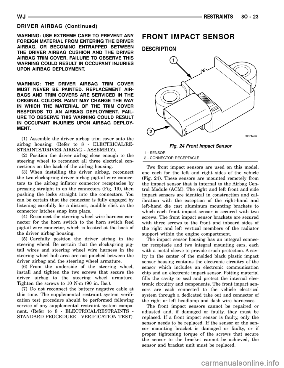
Two front impact sensors are used on this model,
one each for the left and right sides of the vehicle
(Fig. 24). These sensors are mounted remotely from
the impact sensor that is internal to the Airbag Con-
trol Module (ACM). The right and left front and side
impact sensors are identical in construction and cal-
ibration with the exception of the right-hand and
left-hand die cast aluminum mounting brackets to
which each front impact sensor is secured with two
screws. The front impact sensor brackets are secured
with three screws to the front and inboard sides of
the right and left vertical members of the radiator
support within the engine compartment.
The impact sensor housing has an integral connec-
tor receptacle and two integral mounting ears, each
with a metal sleeve to provide crush protection. A cav-
ity in the center of the molded black plastic impact
sensor housing contains the electronic circuitry of the
sensor which includes an electronic communication
chip and an electronic impact sensor. Potting material
fills the cavity to seal and protect the internal elec-
tronic circuitry and components. The front impact sen-
sors are each connected to the vehicle electrical
system through a dedicated take out and connector of
the right or left headlamp and dash wire harnesses.
The front impact sensors cannot be repaired or
adjusted and, if damaged or faulty, they must be
replaced. If a front impact sensor is faulty, only the
sensor needs to be replaced. If the sensor or the sen-
sor mounting bracket is damaged or faulty, or if
proper tightening torque of the screws that secure
the sensor to the bracket cannot be achieved, the
sensor and bracket unit must be replaced.
Fig. 24 Front Impact Sensor
1 - SENSOR
2 - CONNECTOR RECEPTACLE
WJRESTRAINTS 8O - 23
DRIVER AIRBAG (Continued)
Page 569 of 2199
INSTALLATION
The following procedure is for replacement of a
faulty or damaged passenger airbag. If the airbag is
faulty or damaged, but not deployed, review the rec-
ommended procedures for handling non-deployed
supplemental restraints. (Refer to 8 - ELECTRICAL/
RESTRAINTS - STANDARD PROCEDURE - HAN-
DLING NON-DEPLOYED SUPPLEMENTAL
RESTRAINTS). If the passenger airbag has been
deployed, review the recommended procedures for
service after a supplemental restraint deployment
before removing the airbag from the vehicle. (Refer to
8 - ELECTRICAL/RESTRAINTS - STANDARD PRO-
CEDURE - SERVICE AFTER A SUPPLEMENTAL
RESTRAINT DEPLOYMENT).
WARNING: ON VEHICLES EQUIPPED WITH AIR-
BAGS, DISABLE THE SUPPLEMENTAL RESTRAINT
SYSTEM BEFORE ATTEMPTING ANY STEERING
WHEEL, STEERING COLUMN, DRIVER AIRBAG,
PASSENGER AIRBAG, FRONT IMPACT SENSOR,
SIDE IMPACT SENSOR, SIDE CURTAIN AIRBAG, OR
INSTRUMENT PANEL COMPONENT DIAGNOSIS OR
SERVICE. DISCONNECT AND ISOLATE THE BAT-
TERY NEGATIVE (GROUND) CABLE, THEN WAIT
TWO MINUTES FOR THE SYSTEM CAPACITOR TO
DISCHARGE BEFORE PERFORMING FURTHER
DIAGNOSIS OR SERVICE. THIS IS THE ONLY SURE
WAY TO DISABLE THE SUPPLEMENTAL
RESTRAINT SYSTEM. FAILURE TO TAKE THE
PROPER PRECAUTIONS COULD RESULT IN ACCI-
DENTAL AIRBAG DEPLOYMENT AND POSSIBLE
PERSONAL INJURY.
WARNING: WHEN REMOVING A DEPLOYED AIR-
BAG, RUBBER GLOVES, EYE PROTECTION, AND A
LONG-SLEEVED SHIRT SHOULD BE WORN. THERE
MAY BE DEPOSITS ON THE AIRBAG UNIT AND
OTHER INTERIOR SURFACES. IN LARGE DOSES,
THESE DEPOSITS MAY CAUSE IRRITATION TO THE
SKIN AND EYES.
WARNING: USE EXTREME CARE TO PREVENT ANY
FOREIGN MATERIAL FROM ENTERING THE PAS-
SENGER AIRBAG, OR BECOMING ENTRAPPED
BETWEEN THE PASSENGER AIRBAG CUSHION
AND THE INSTRUMENT PANEL TOP PAD. FAILURE
TO OBSERVE THIS WARNING COULD RESULT IN
OCCUPANT INJURIES UPON AIRBAG DEPLOY-
MENT.WARNING: THE INSTRUMENT PANEL TOP PAD
MUST NEVER BE PAINTED. REPLACEMENT TOP
PADS ARE SERVICED IN THE ORIGINAL COLORS.
PAINT MAY CHANGE THE WAY IN WHICH THE
MATERIAL OF THE TOP PAD RESPONDS TO AN
AIRBAG DEPLOYMENT. FAILURE TO OBSERVE
THIS WARNING COULD RESULT IN OCCUPANT
INJURIES UPON AIRBAG DEPLOYMENT.
(1) Carefully position the passenger airbag onto
the instrument panel structural duct (Fig. 32).
(2) Install and tighten the four screws that secure
the passenger airbag to the instrument panel struc-
tural duct. Tighten the screws to 11.8 N´m (105 in.
lbs.).
(3) Reconnect the instrument panel wire harness
connector for the passenger airbag to the passenger
airbag pigtail wire connector. This connector is
secured to the outside of the outboard airbag unit
end bracket. Be certain that the latch on the connec-
tor and the red Connector Position Assurance (CPA)
lock are each fully engaged.
(4) Reinstall the top pad onto the instrument
panel. (Refer to 23 - BODY/INSTRUMENT PANEL/
INSTRUMENT PANEL TOP PAD - INSTALLA-
TION).
(5) Do not reconnect the battery negative cable at
this time. The supplemental restraint system verifi-
cation test procedure should be performed following
service of any supplemental restraint system compo-
nent. (Refer to 8 - ELECTRICAL/RESTRAINTS -
STANDARD PROCEDURE - VERIFICATION TEST).
REAR CENTER SEAT BELT &
RETRACTOR
REMOVAL
WARNING: DURING AND FOLLOWING ANY SEAT
BELT SERVICE, CAREFULLY INSPECT ALL SEAT
BELTS, BUCKLES, MOUNTING HARDWARE, AND
RETRACTORS FOR PROPER INSTALLATION,
OPERATION, OR DAMAGE. REPLACE ANY BELT
THAT IS CUT, FRAYED, OR TORN. STRAIGHTEN
ANY BELT THAT IS TWISTED. TIGHTEN ANY
LOOSE FASTENERS. REPLACE ANY BELT THAT
HAS A DAMAGED OR INOPERATIVE BUCKLE OR
RETRACTOR. REPLACE ANY BELT THAT HAS A
BENT OR DAMAGED LATCH PLATE OR ANCHOR
PLATE. NEVER ATTEMPT TO REPAIR A SEAT BELT
COMPONENT. ALWAYS REPLACE DAMAGED OR
FAULTY SEAT BELT COMPONENTS WITH THE COR-
RECT, NEW AND UNUSED REPLACEMENT PARTS
LISTED IN THE MOPAR PARTS CATALOG.
8O - 32 RESTRAINTSWJ
PASSENGER AIRBAG (Continued)
Page 660 of 2199
TERMINOLOGY
This is a list of terms and definitions used in the
wiring diagrams.
LHD .................Left Hand Drive Vehicles
RHD................Right Hand Drive Vehicles
ATX . . Automatic Transmissions-Front Wheel Drive
MTX....Manual Transmissions-Front Wheel Drive
AT ....Automatic Transmissions-Rear Wheel Drive
MT .....Manual Transmissions-Rear Wheel Drive
SOHC...........Single Over Head Cam Engine
DOHC..........Double Over Head Cam Engine
Built-Up-Export........ Vehicles Built For Sale In
Markets Other Than North America
Except Built-Up-Export . . Vehicles Built For Sale In
North America
DESCRIPTION - CIRCUIT INFORMATION
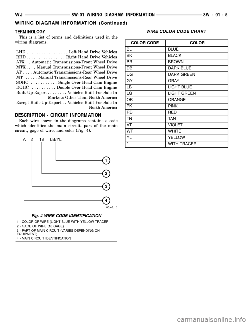
Each wire shown in the diagrams contains a code
which identifies the main circuit, part of the main
circuit, gage of wire, and color (Fig. 4).
WIRE COLOR CODE CHART
COLOR CODE COLOR
BL BLUE
BK BLACK
BR BROWN
DB DARK BLUE
DG DARK GREEN
GY GRAY
LB LIGHT BLUE
LG LIGHT GREEN
OR ORANGE
PK PINK
RD RED
TN TAN
VT VIOLET
WT WHITE
YL YELLOW
* WITH TRACER
Fig. 4 WIRE CODE IDENTIFICATION
1 - COLOR OF WIRE (LIGHT BLUE WITH YELLOW TRACER
2 - GAGE OF WIRE (18 GAGE)
3 - PART OF MAIN CIRCUIT (VARIES DEPENDING ON
EQUIPMENT)
4 - MAIN CIRCUIT IDENTIFICATION
WJ8W-01 WIRING DIAGRAM INFORMATION 8W - 01 - 5
WIRING DIAGRAM INFORMATION (Continued)
Page 669 of 2199
DIODE
REMOVAL
(1) Disconnect the battery.
(2) Locate the diode in the harness, and remove
the protective covering.
(3) Remove the diode from the harness, pay atten-
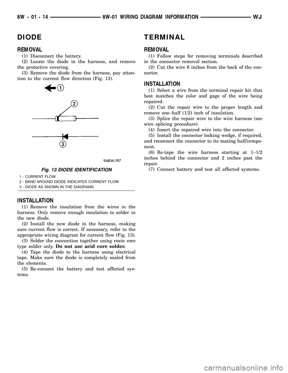
tion to the current flow direction (Fig. 13).
INSTALLATION
(1) Remove the insulation from the wires in the
harness. Only remove enough insulation to solder in
the new diode.
(2) Install the new diode in the harness, making
sure current flow is correct. If necessary, refer to the
appropriate wiring diagram for current flow (Fig. 13).
(3) Solder the connection together using rosin core
type solder only.Do not use acid core solder.
(4) Tape the diode to the harness using electrical
tape. Make sure the diode is completely sealed from
the elements.
(5) Re-connect the battery and test affected sys-
tems.
TERMINAL
REMOVAL
(1) Follow steps for removing terminals described
in the connector removal section.
(2) Cut the wire 6 inches from the back of the con-
nector.
INSTALLATION
(1) Select a wire from the terminal repair kit that
best matches the color and gage of the wire being
repaired.
(2) Cut the repair wire to the proper length and
remove one±half (1/2) inch of insulation.
(3) Splice the repair wire to the wire harness (see
wire splicing procedure).
(4) Insert the repaired wire into the connector.
(5) Install the connector locking wedge, if required,
and reconnect the connector to its mating half/compo-
nent.
(6) Re-tape the wire harness starting at 1±1/2
inches behind the connector and 2 inches past the
repair.
(7) Connect battery and test all affected systems.
Fig. 13 DIODE IDENTIFICATION
1 - CURRENT FLOW
2 - BAND AROUND DIODE INDICATES CURRENT FLOW
3 - DIODE AS SHOWN IN THE DIAGRAMS
8W - 01 - 14 8W-01 WIRING DIAGRAM INFORMATIONWJ
Page 1176 of 2199
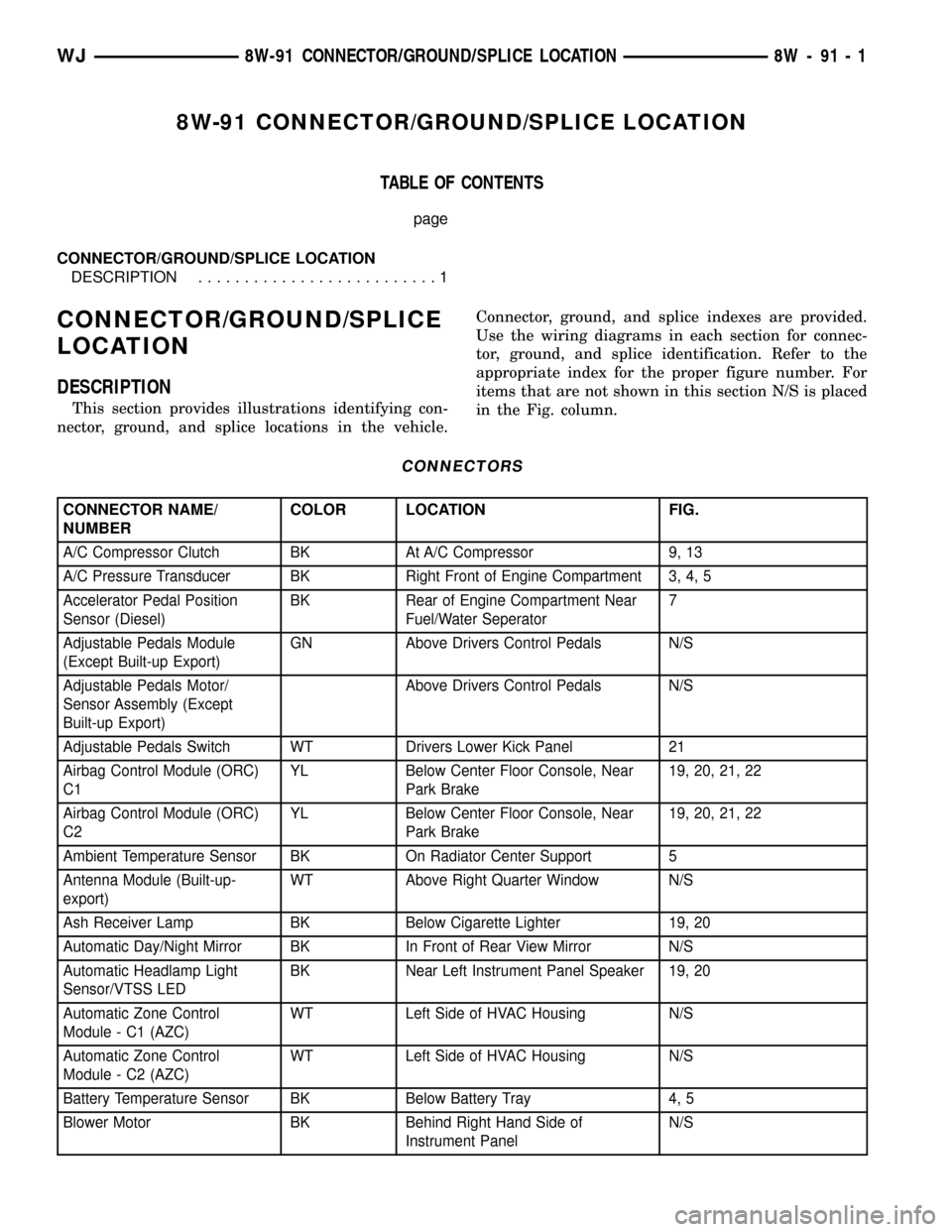
8W-91 CONNECTOR/GROUND/SPLICE LOCATION
TABLE OF CONTENTS
page
CONNECTOR/GROUND/SPLICE LOCATION
DESCRIPTION..........................1
CONNECTOR/GROUND/SPLICE
LOCATION
DESCRIPTION
This section provides illustrations identifying con-
nector, ground, and splice locations in the vehicle.Connector, ground, and splice indexes are provided.
Use the wiring diagrams in each section for connec-
tor, ground, and splice identification. Refer to the
appropriate index for the proper figure number. For
items that are not shown in this section N/S is placed
in the Fig. column.
CONNECTORS
CONNECTOR NAME/
NUMBERCOLOR LOCATION FIG.
A/C Compressor Clutch BK At A/C Compressor 9, 13
A/C Pressure Transducer BK Right Front of Engine Compartment 3, 4, 5
Accelerator Pedal Position
Sensor (Diesel)BK Rear of Engine Compartment Near
Fuel/Water Seperator7
Adjustable Pedals Module
(Except Built-up Export)GN Above Drivers Control Pedals N/S
Adjustable Pedals Motor/
Sensor Assembly (Except
Built-up Export)Above Drivers Control Pedals N/S
Adjustable Pedals Switch WT Drivers Lower Kick Panel 21
Airbag Control Module (ORC)
C1YL Below Center Floor Console, Near
Park Brake19, 20, 21, 22
Airbag Control Module (ORC)
C2YL Below Center Floor Console, Near
Park Brake19, 20, 21, 22
Ambient Temperature Sensor BK On Radiator Center Support 5
Antenna Module (Built-up-
export)WT Above Right Quarter Window N/S
Ash Receiver Lamp BK Below Cigarette Lighter 19, 20
Automatic Day/Night Mirror BK In Front of Rear View Mirror N/S
Automatic Headlamp Light
Sensor/VTSS LEDBK Near Left Instrument Panel Speaker 19, 20
Automatic Zone Control
Module - C1 (AZC)WT Left Side of HVAC Housing N/S
Automatic Zone Control
Module - C2 (AZC)WT Left Side of HVAC Housing N/S
Battery Temperature Sensor BK Below Battery Tray 4, 5
Blower Motor BK Behind Right Hand Side of
Instrument PanelN/S
WJ8W-91 CONNECTOR/GROUND/SPLICE LOCATION 8W - 91 - 1
Page 1177 of 2199
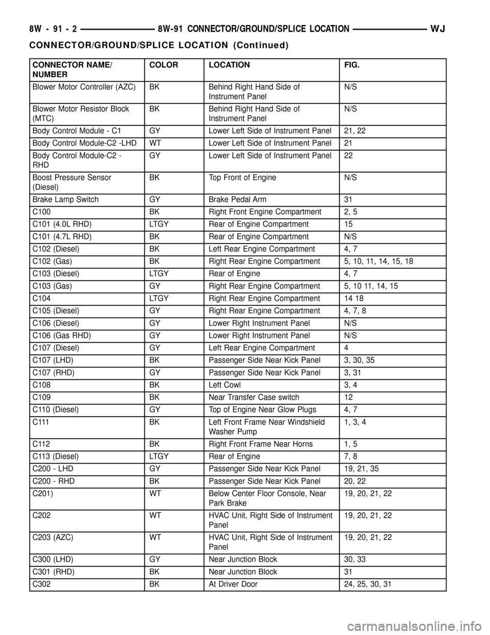
CONNECTOR NAME/
NUMBERCOLOR LOCATION FIG.
Blower Motor Controller (AZC) BK Behind Right Hand Side of
Instrument PanelN/S
Blower Motor Resistor Block
(MTC)BK Behind Right Hand Side of
Instrument PanelN/S
Body Control Module - C1 GY Lower Left Side of Instrument Panel 21, 22
Body Control Module-C2 -LHD WT Lower Left Side of Instrument Panel 21
Body Control Module-C2 -
RHDGY Lower Left Side of Instrument Panel 22
Boost Pressure Sensor
(Diesel)BK Top Front of Engine N/S
Brake Lamp Switch GY Brake Pedal Arm 31
C100 BK Right Front Engine Compartment 2, 5
C101 (4.0L RHD) LTGY Rear of Engine Compartment 15
C101 (4.7L RHD) BK Rear of Engine Compartment N/S
C102 (Diesel) BK Left Rear Engine Compartment 4, 7
C102 (Gas) BK Right Rear Engine Compartment 5, 10, 11, 14, 15, 18
C103 (Diesel) LTGY Rear of Engine 4, 7
C103 (Gas) GY Right Rear Engine Compartment 5, 10 11, 14, 15
C104 LTGY Right Rear Engine Compartment 14 18
C105 (Diesel) GY Right Rear Engine Compartment 4, 7, 8
C106 (Diesel) GY Lower Right Instrument Panel N/S
C106 (Gas RHD) GY Lower Right Instrument Panel N/S
C107 (Diesel) GY Left Rear Engine Compartment 4
C107 (LHD) BK Passenger Side Near Kick Panel 3, 30, 35
C107 (RHD) GY Passenger Side Near Kick Panel 3, 31
C108 BK Left Cowl 3, 4
C109 BK Near Transfer Case switch 12
C110 (Diesel) GY Top of Engine Near Glow Plugs 4, 7
C111 BK Left Front Frame Near Windshield
Washer Pump1, 3, 4
C112 BK Right Front Frame Near Horns 1, 5
C113 (Diesel) LTGY Rear of Engine 7, 8
C200 - LHD GY Passenger Side Near Kick Panel 19, 21, 35
C200 - RHD BK Passenger Side Near Kick Panel 20, 22
C201) WT Below Center Floor Console, Near
Park Brake19, 20, 21, 22
C202 WT HVAC Unit, Right Side of Instrument
Panel19, 20, 21, 22
C203 (AZC) WT HVAC Unit, Right Side of Instrument
Panel19, 20, 21, 22
C300 (LHD) GY Near Junction Block 30, 33
C301 (RHD) BK Near Junction Block 31
C302 BK At Driver Door 24, 25, 30, 31
8W - 91 - 2 8W-91 CONNECTOR/GROUND/SPLICE LOCATIONWJ
CONNECTOR/GROUND/SPLICE LOCATION (Continued)
Page 1178 of 2199
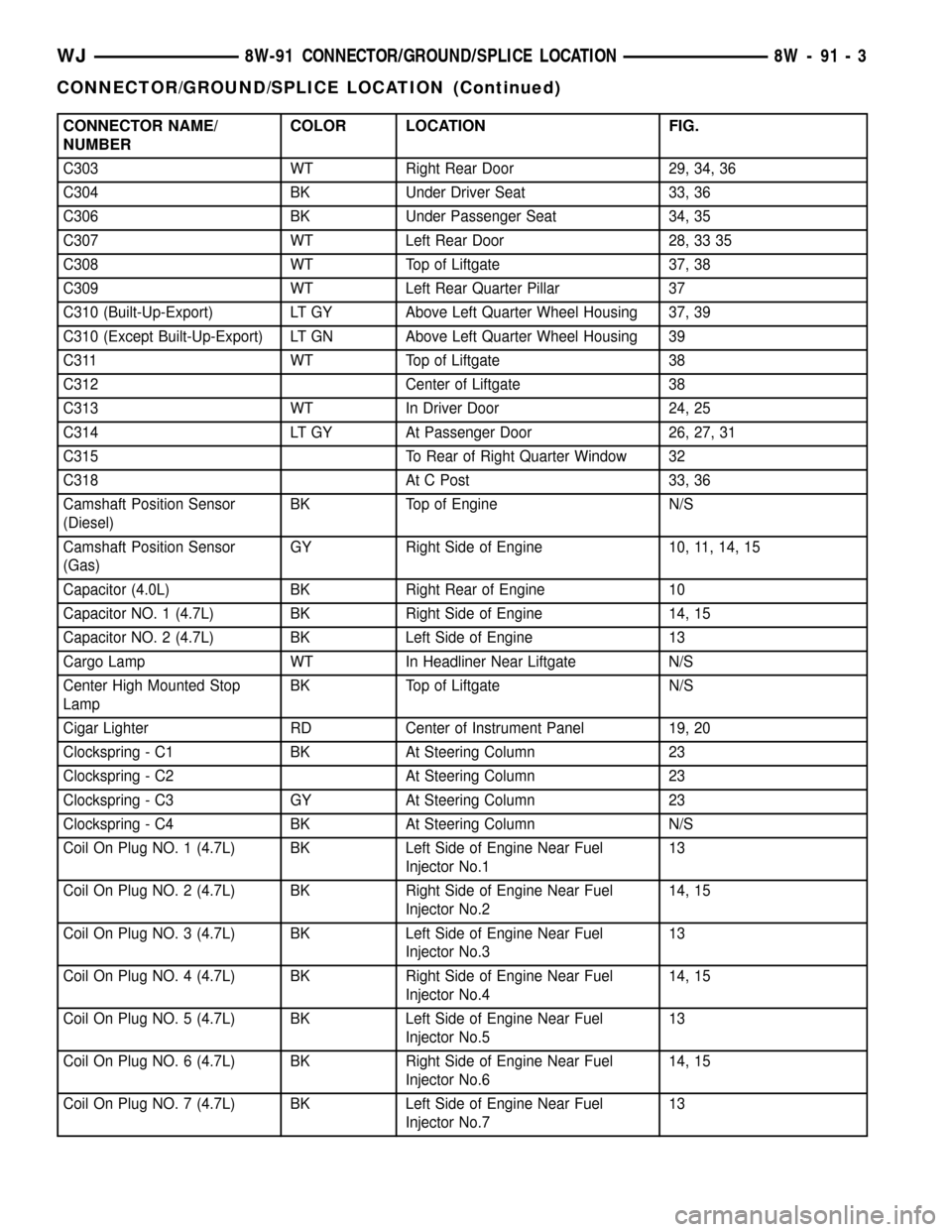
CONNECTOR NAME/
NUMBERCOLOR LOCATION FIG.
C303 WT Right Rear Door 29, 34, 36
C304 BK Under Driver Seat 33, 36
C306 BK Under Passenger Seat 34, 35
C307 WT Left Rear Door 28, 33 35
C308 WT Top of Liftgate 37, 38
C309 WT Left Rear Quarter Pillar 37
C310 (Built-Up-Export) LT GY Above Left Quarter Wheel Housing 37, 39
C310 (Except Built-Up-Export) LT GN Above Left Quarter Wheel Housing 39
C311 WT Top of Liftgate 38
C312 Center of Liftgate 38
C313 WT In Driver Door 24, 25
C314 LT GY At Passenger Door 26, 27, 31
C315 To Rear of Right Quarter Window 32
C318 At C Post 33, 36
Camshaft Position Sensor
(Diesel)BK Top of Engine N/S
Camshaft Position Sensor
(Gas)GY Right Side of Engine 10, 11, 14, 15
Capacitor (4.0L) BK Right Rear of Engine 10
Capacitor NO. 1 (4.7L) BK Right Side of Engine 14, 15
Capacitor NO. 2 (4.7L) BK Left Side of Engine 13
Cargo Lamp WT In Headliner Near Liftgate N/S
Center High Mounted Stop
LampBK Top of Liftgate N/S
Cigar Lighter RD Center of Instrument Panel 19, 20
Clockspring - C1 BK At Steering Column 23
Clockspring - C2 At Steering Column 23
Clockspring - C3 GY At Steering Column 23
Clockspring - C4 BK At Steering Column N/S
Coil On Plug NO. 1 (4.7L) BK Left Side of Engine Near Fuel
Injector No.113
Coil On Plug NO. 2 (4.7L) BK Right Side of Engine Near Fuel
Injector No.214, 15
Coil On Plug NO. 3 (4.7L) BK Left Side of Engine Near Fuel
Injector No.313
Coil On Plug NO. 4 (4.7L) BK Right Side of Engine Near Fuel
Injector No.414, 15
Coil On Plug NO. 5 (4.7L) BK Left Side of Engine Near Fuel
Injector No.513
Coil On Plug NO. 6 (4.7L) BK Right Side of Engine Near Fuel
Injector No.614, 15
Coil On Plug NO. 7 (4.7L) BK Left Side of Engine Near Fuel
Injector No.713
WJ8W-91 CONNECTOR/GROUND/SPLICE LOCATION 8W - 91 - 3
CONNECTOR/GROUND/SPLICE LOCATION (Continued)
Page 1179 of 2199
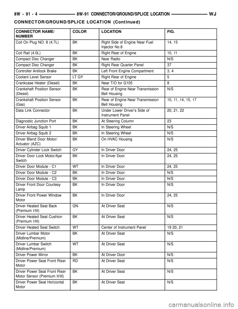
CONNECTOR NAME/
NUMBERCOLOR LOCATION FIG.
Coil On Plug NO. 8 (4.7L) BK Right Side of Engine Near Fuel
Injector No.814, 15
Coil Rail (4.0L) BK Right Rear of Engine 10, 11
Compact Disc Changer BK Near Radio N/S
Compact Disc Changer BK Right Rear Quarter Panel 37
Controller Antilock Brake BK Left Front Engine Compartment 3, 4
Coolant Level Sensor LT GY Right Rear of Engine 5
Crankcase Heater (Diesel) BK Near T/O for G105 8
Crankshaft Position Sensor
(Diesel)BK Rear of Engine Near Transmission
Bell HousingN/S
Crankshaft Position Sensor
(Gas)BK Rear of Engine Near Transmission
Bell Housing10, 11, 14, 15, 17
Data Link Connector BK Under Lower Driver's Side of
Instrument Panel20, 21, 22
Diagnostic Junction Port BK At Steering Column 23
Driver Airbag Squib 1 BK In Steering Wheel N/S
Driver Airbag Squib 2 BK In Steering Wheel N/S
Driver Blend Door Motor/
Actuator (AZC)BK On HVAC Housing N/S
Driver Cylinder Lock Switch GY In Driver Door 24, 25
Driver Door Lock Motor/Ajar
SwitchBK In Driver Door 24, 25
Driver Door Module - C1 WT In Driver Door 24, 25
Driver Door Module - C2 BK In Driver Door N/S
Driver Door Module - C3 BK In Driver Door N/S
Driver Front Door Courtesy
LampBK In Driver Door N/S
Driver Front Power Window
MotorBK In Driver Door 24, 25
Driver Heated Seat Back
(Premium I/III)GN At Driver Seat N/S
Driver Heated Seat Cushion
(Premium I/III)BK At Driver Seat N/S
Driver Heated Seat Switch WT Center of Instrument Panel 19 20, 21
Driver Lumbar Motor
(Midline/Premium)BK At Driver Seat N/S
Driver Lumbar Switch
(Midline/Premium)WT At Driver Seat N/S
Driver Power Mirror BK At Driver Door N/S
Driver Power Seat Front Riser
MotorRD At Driver Seat N/S
Driver Power Seat Front Riser
Motor Sensor (Premium II/III)BK At Driver Seat N/S
Driver Power Seat Horizontal
MotorBK At Driver Seat N/S
8W - 91 - 4 8W-91 CONNECTOR/GROUND/SPLICE LOCATIONWJ
CONNECTOR/GROUND/SPLICE LOCATION (Continued)
Page 1180 of 2199
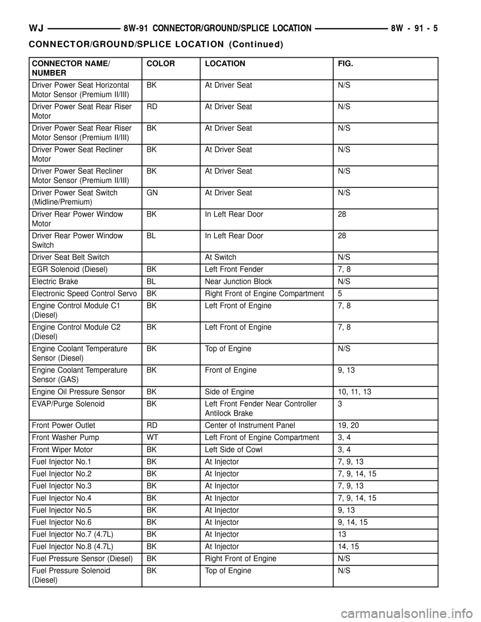
CONNECTOR NAME/
NUMBERCOLOR LOCATION FIG.
Driver Power Seat Horizontal
Motor Sensor (Premium II/III)BK At Driver Seat N/S
Driver Power Seat Rear Riser
MotorRD At Driver Seat N/S
Driver Power Seat Rear Riser
Motor Sensor (Premium II/III)BK At Driver Seat N/S
Driver Power Seat Recliner
MotorBK At Driver Seat N/S
Driver Power Seat Recliner
Motor Sensor (Premium II/III)BK At Driver Seat N/S
Driver Power Seat Switch
(Midline/Premium)GN At Driver Seat N/S
Driver Rear Power Window
MotorBK In Left Rear Door 28
Driver Rear Power Window
SwitchBL In Left Rear Door 28
Driver Seat Belt Switch At Switch N/S
EGR Solenoid (Diesel) BK Left Front Fender 7, 8
Electric Brake BL Near Junction Block N/S
Electronic Speed Control Servo BK Right Front of Engine Compartment 5
Engine Control Module C1
(Diesel)BK Left Front of Engine 7, 8
Engine Control Module C2
(Diesel)BK Left Front of Engine 7, 8
Engine Coolant Temperature
Sensor (Diesel)BK Top of Engine N/S
Engine Coolant Temperature
Sensor (GAS)BK Front of Engine 9, 13
Engine Oil Pressure Sensor BK Side of Engine 10, 11, 13
EVAP/Purge Solenoid BK Left Front Fender Near Controller
Antilock Brake3
Front Power Outlet RD Center of Instrument Panel 19, 20
Front Washer Pump WT Left Front of Engine Compartment 3, 4
Front Wiper Motor BK Left Side of Cowl 3, 4
Fuel Injector No.1 BK At Injector 7, 9, 13
Fuel Injector No.2 BK At Injector 7, 9, 14, 15
Fuel Injector No.3 BK At Injector 7, 9, 13
Fuel Injector No.4 BK At Injector 7, 9, 14, 15
Fuel Injector No.5 BK At Injector 9, 13
Fuel Injector No.6 BK At Injector 9, 14, 15
Fuel Injector No.7 (4.7L) BK At Injector 13
Fuel Injector No.8 (4.7L) BK At Injector 14, 15
Fuel Pressure Sensor (Diesel) BK Right Front of Engine N/S
Fuel Pressure Solenoid
(Diesel)BK Top of Engine N/S
WJ8W-91 CONNECTOR/GROUND/SPLICE LOCATION 8W - 91 - 5
CONNECTOR/GROUND/SPLICE LOCATION (Continued)
Page 1181 of 2199
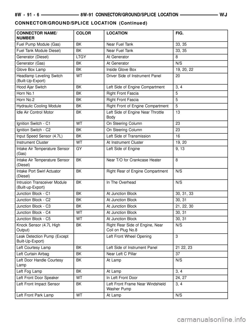
CONNECTOR NAME/
NUMBERCOLOR LOCATION FIG.
Fuel Pump Module (Gas) BK Near Fuel Tank 33, 35
Fuel Tank Module Diesel) BK Near Fuel Tank 33, 35
Generator (Diesel) LTGY At Generator 8
Generator (Gas) BK At Generator N/S
Glove Box Lamp BK Inside Glove Box 19, 20, 22
Headlamp Leveling Switch
(Built-Up-Export)WT Driver Side of Instrument Panel 20
Hood Ajar Switch BK Left Side of Engine Compartment 3, 4
Horn No.1 BK Right Front Fascia 5
Horn No.2 BK Right Front Fascia 5
Hydraulic Cooling Module BK Right Front of Engine Compartment 5
Idle Air Control Motor BK Left Side of Engine Near Throttle
Body13
Ignition Switch - C1 WT On Steering Column 23
Ignition Switch - C2 BK On Steering Column 23
Input Speed Sensor (4.7L) BK Left Side of Transmission 16
Instrument Cluster WT At Instrument Cluster 19, 20
Intake Air Temperature Sensor
(Gas)GY Left Side of Engine 9, 13
Intake Air Temperature Sensor
(Diesel)BK Near T/O for Crankcase Heater 8
Intake Port Swirl Actuator
(Diesel)BK Right Rear of Engine Compartment N/S
Intrusion Transceiver Module
(Built-up-Export)BK In The Overhead N/S
Junction Block - C1 BK At Junction Block 30, 31, 33
Junction Block - C2 BK At Junction Block 30, 31
Junction Block - C3 BK At Junction Block 21, 22, 30
Junction Block - C4 WT At Junction Block 30, 31
Junction Block - C5 WT At Junction Block 30, 31
Knock Sensor (4.7L High
Output)BK Right Rear Side of Engine, Near
Coil on Plug No.8N/S
Leak Detection Pump (Except
Built-Up-Export)Left Front Wheel Opening 3
Left Courtesy Lamp BK Left Side of Instrument Panel 21 22, 23
Left Curtain Airbag BK Near Left C Pillar 37
Left Door Handle Courtesy
LampBK At Lamp N/S
Left Fog Lamp BK At Lamp 3, 4
Left Front Door Speaker WT In Left Front Door 24, 27
Left Front Impact Sensor BK Left Front Frame Near Windshield
Washer Pump3, 4
Left Front Park Lamp WT At Lamp N/S
8W - 91 - 6 8W-91 CONNECTOR/GROUND/SPLICE LOCATIONWJ
CONNECTOR/GROUND/SPLICE LOCATION (Continued)