Sentry Key Immobilizer JEEP GRAND CHEROKEE 2002 WJ / 2.G Owner's Manual
[x] Cancel search | Manufacturer: JEEP, Model Year: 2002, Model line: GRAND CHEROKEE, Model: JEEP GRAND CHEROKEE 2002 WJ / 2.GPages: 2199, PDF Size: 76.01 MB
Page 864 of 2199
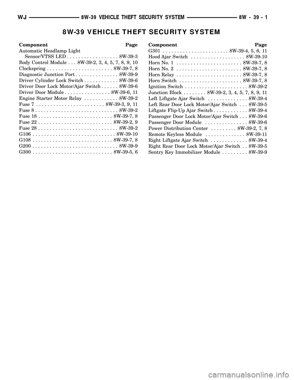
8W-39 VEHICLE THEFT SECURITY SYSTEM
Component Page
Automatic Headlamp Light
Sensor/VTSS LED.................. 8W-39-3
Body Control Module . . . 8W-39-2, 3, 4, 5, 7, 8, 9, 10
Clockspring....................... 8W-39-7, 8
Diagnostic Junction Port............... 8W-39-9
Driver Cylinder Lock Switch............ 8W-39-6
Driver Door Lock Motor/Ajar Switch...... 8W-39-6
Driver Door Module................ 8W-39-6, 11
Engine Starter Motor Relay............ 8W-39-2
Fuse 7........................ 8W-39-3, 9, 11
Fuse 8............................. 8W-39-2
Fuse 18.......................... 8W-39-7, 8
Fuse 22.......................... 8W-39-2, 9
Fuse 28............................ 8W-39-2
G106............................. 8W-39-10
G108............................ 8W-39-7, 8
G200.............................. 8W-39-9
G300............................ 8W-39-5, 6Component Page
G301....................... 8W-39-4, 5, 6, 11
Hood Ajar Switch................... 8W-39-10
Horn No. 1....................... 8W-39-7, 8
Horn No. 2....................... 8W-39-7, 8
Horn Relay....................... 8W-39-7, 8
Horn Switch...................... 8W-39-7, 8
Ignition Switch...................... 8W-39-2
Junction Block........ 8W-39-2, 3, 4, 5, 7, 8, 9, 11
Left Liftgate Ajar Switch.............. 8W-39-4
Left Rear Door Lock Motor/Ajar Switch . . . 8W-39-5
Liftgate Flip-Up Ajar Switch............ 8W-39-4
Passenger Door Lock Motor/Ajar Switch . . . 8W-39-6
Passenger Door Module............... 8W-39-6
Power Distribution Center......... 8W-39-2, 7, 8
Remote Keyless Module.............. 8W-39-11
Right Liftgate Ajar Switch............. 8W-39-4
Right Rear Door Lock Motor/Ajar Switch . . 8W-39-5
Sentry Key Immobilizer Module......... 8W-39-9
WJ8W-39 VEHICLE THEFT SECURITY SYSTEM 8W - 39 - 1
Page 1052 of 2199
Component Page
RIGHT FRONT WHEEL SPEED
SENSOR....................... 8W-80-115
RIGHT HEADLAMP LEVELING MOTOR
(BUILT-UP-EXPORT)............. 8W-80-115
RIGHT HIGH BEAM HEADLAMP..... 8W-80-116
RIGHT INSTRUMENT PANEL
SPEAKER...................... 8W-80-116
RIGHT LIFTGATE AJAR SWITCH..... 8W-80-116
RIGHT LOW BEAM HEADLAMP..... 8W-80-116
RIGHT MULTI-FUNCTION SWITCH . . . 8W-80-116
RIGHT REAR DOOR LOCK
MOTOR/AJAR SWITCH........... 8W-80-117
RIGHT REAR DOOR SPEAKER....... 8W-80-117
RIGHT REAR LAMP ASSEMBLY...... 8W-80-117
RIGHT REAR WHEEL SPEED
SENSOR....................... 8W-80-117
RIGHT REMOTE RADIO SWITCH.... 8W-80-117
RIGHT SIDE REPEATER LAMP
(BUILT-UP-EXPORT)............. 8W-80-118
RIGHT VISOR/VANITY LAMP........ 8W-80-118
SEAT BELT SWITCH............... 8W-80-118
SEAT MODULE C1 (PREMIUM)...... 8W-80-118
SEAT MODULE C2 (PREMIUM)...... 8W-80-119
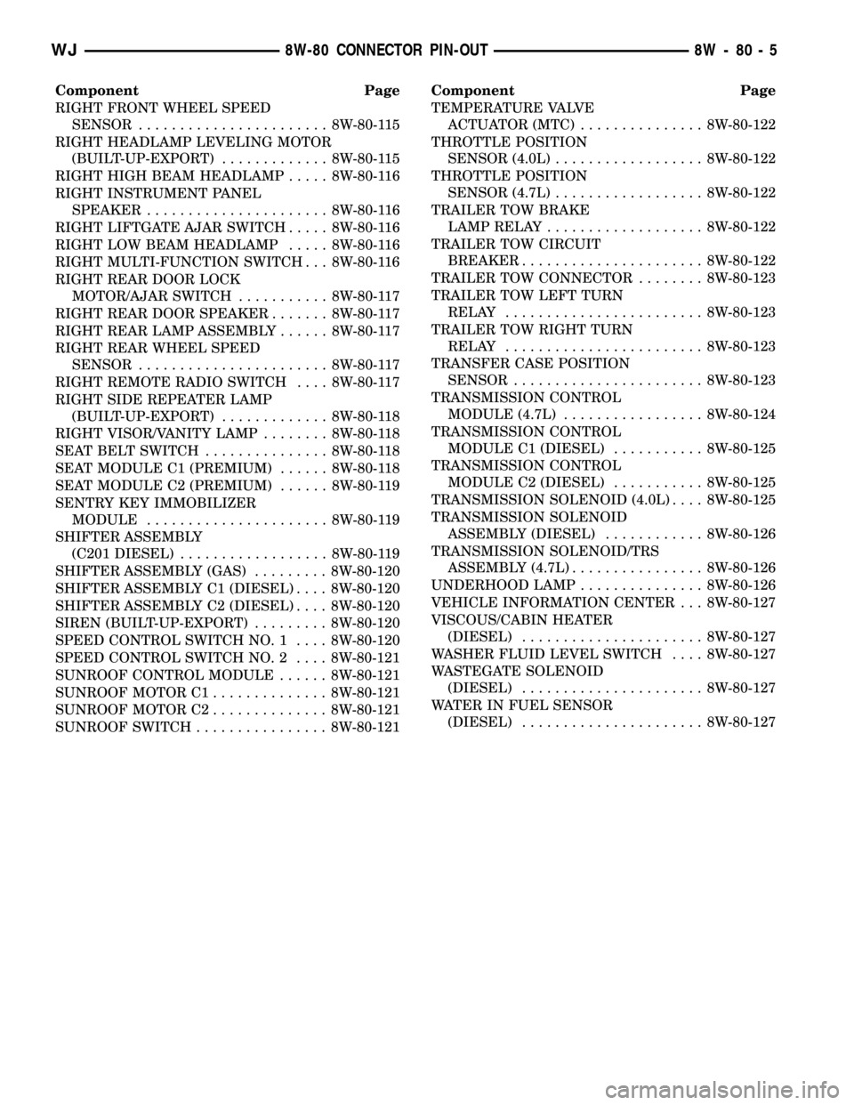
SENTRY KEY IMMOBILIZER
MODULE...................... 8W-80-119
SHIFTER ASSEMBLY
(C201 DIESEL).................. 8W-80-119
SHIFTER ASSEMBLY (GAS)......... 8W-80-120
SHIFTER ASSEMBLY C1 (DIESEL).... 8W-80-120
SHIFTER ASSEMBLY C2 (DIESEL).... 8W-80-120
SIREN (BUILT-UP-EXPORT)......... 8W-80-120
SPEED CONTROL SWITCH NO. 1.... 8W-80-120
SPEED CONTROL SWITCH NO. 2.... 8W-80-121
SUNROOF CONTROL MODULE...... 8W-80-121
SUNROOF MOTOR C1.............. 8W-80-121
SUNROOF MOTOR C2.............. 8W-80-121
SUNROOF SWITCH................ 8W-80-121Component Page
TEMPERATURE VALVE
ACTUATOR (MTC)............... 8W-80-122
THROTTLE POSITION
SENSOR (4.0L).................. 8W-80-122
THROTTLE POSITION
SENSOR (4.7L).................. 8W-80-122
TRAILER TOW BRAKE
LAMP RELAY................... 8W-80-122
TRAILER TOW CIRCUIT
BREAKER...................... 8W-80-122
TRAILER TOW CONNECTOR........ 8W-80-123
TRAILER TOW LEFT TURN
RELAY........................ 8W-80-123
TRAILER TOW RIGHT TURN
RELAY........................ 8W-80-123
TRANSFER CASE POSITION
SENSOR....................... 8W-80-123
TRANSMISSION CONTROL
MODULE (4.7L)................. 8W-80-124
TRANSMISSION CONTROL
MODULE C1 (DIESEL)........... 8W-80-125
TRANSMISSION CONTROL
MODULE C2 (DIESEL)........... 8W-80-125
TRANSMISSION SOLENOID (4.0L).... 8W-80-125
TRANSMISSION SOLENOID
ASSEMBLY (DIESEL)............ 8W-80-126
TRANSMISSION SOLENOID/TRS
ASSEMBLY (4.7L)................ 8W-80-126
UNDERHOOD LAMP............... 8W-80-126
VEHICLE INFORMATION CENTER . . . 8W-80-127
VISCOUS/CABIN HEATER
(DIESEL)...................... 8W-80-127
WASHER FLUID LEVEL SWITCH.... 8W-80-127
WASTEGATE SOLENOID
(DIESEL)...................... 8W-80-127
WATER IN FUEL SENSOR
(DIESEL)...................... 8W-80-127
WJ8W-80 CONNECTOR PIN-OUT 8W - 80 - 5
Page 1166 of 2199
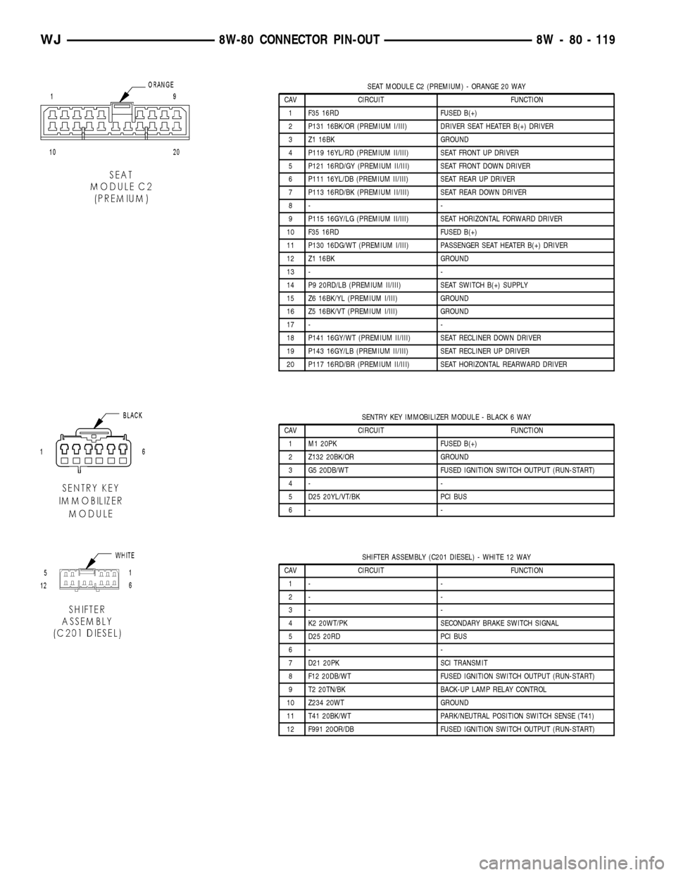
SEAT MODULE C2 (PREMIUM) - ORANGE 20 WAY
CAV CIRCUIT FUNCTION
1 F35 16RD FUSED B(+)
2 P131 16BK/OR (PREMIUM I/III) DRIVER SEAT HEATER B(+) DRIVER
3 Z1 16BK GROUND
4 P119 16YL/RD (PREMIUM II/III) SEAT FRONT UP DRIVER
5 P121 16RD/GY (PREMIUM II/III) SEAT FRONT DOWN DRIVER
6 P111 16YL/DB (PREMIUM II/III) SEAT REAR UP DRIVER
7 P113 16RD/BK (PREMIUM II/III) SEAT REAR DOWN DRIVER
8- -
9 P115 16GY/LG (PREMIUM II/III) SEAT HORIZONTAL FORWARD DRIVER
10 F35 16RD FUSED B(+)
11 P130 16DG/WT (PREMIUM I/III) PASSENGER SEAT HEATER B(+) DRIVER
12 Z1 16BK GROUND
13 - -
14 P9 20RD/LB (PREMIUM II/III) SEAT SWITCH B(+) SUPPLY
15 Z6 16BK/YL (PREMIUM I/III) GROUND
16 Z5 16BK/VT (PREMIUM I/III) GROUND
17 - -
18 P141 16GY/WT (PREMIUM II/III) SEAT RECLINER DOWN DRIVER
19 P143 16GY/LB (PREMIUM II/III) SEAT RECLINER UP DRIVER
20 P117 16RD/BR (PREMIUM II/III) SEAT HORIZONTAL REARWARD DRIVER
SENTRY KEY IMMOBILIZER MODULE - BLACK 6 WAY
CAV CIRCUIT FUNCTION
1 M1 20PK FUSED B(+)
2 Z132 20BK/OR GROUND
3 G5 20DB/WT FUSED IGNITION SWITCH OUTPUT (RUN-START)
4- -
5 D25 20YL/VT/BK PCI BUS
6- -
SHIFTER ASSEMBLY (C201 DIESEL) - WHITE 12 WAY
CAV CIRCUIT FUNCTION
1- -
2- -
3- -
4 K2 20WT/PK SECONDARY BRAKE SWITCH SIGNAL
5 D25 20RD PCI BUS
6- -
7 D21 20PK SCI TRANSMIT
8 F12 20DB/WT FUSED IGNITION SWITCH OUTPUT (RUN-START)
9 T2 20TN/BK BACK-UP LAMP RELAY CONTROL
10 Z234 20WT GROUND
11 T41 20BK/WT PARK/NEUTRAL POSITION SWITCH SENSE (T41)
12 F991 20OR/DB FUSED IGNITION SWITCH OUTPUT (RUN-START)
WJ8W-80 CONNECTOR PIN-OUT 8W - 80 - 119
Page 1185 of 2199
CONNECTOR NAME/
NUMBERCOLOR LOCATION FIG.
Right Front Park/Turn Signal
Lamp (Except Built-Up-Export)BK At Lamp N/S
Right Front Side Marker Lamp
(Except Built-Up-Export)WT At Lamp N/S
Right Front Turn Signal Lamp
(Built-Up-Export)WT At Lamp N/S
Right Front Wheel Speed
SensorGY In Right Front Wheel Opening N/S
Right Headlamp Leveling
Motor (Built-Up-Export)BK At Motor N/S
Right High Beam Headlamp BK At Lamp N/S
Right Instrument Panel
SpeakerWT At Speaker 19, 20
Right Liftgate Ajar Switch BK In Liftgate 38
Right Low Beam Headlamp GY At Lamp N/S
Right Multi-Function Switch WT On Steering Column 23
Right Rear Door Lock
Motor/Ajar SwitchBK In Right Rear Door 29
Right Rear Door Speaker WT In Right Rear Door 29
Right Rear Lamp Assembly BK At Lamp Assembly 37
Right Rear Wheel Speed
SensorBK Near Right Rear Wheel 33, 35
Right Remote Radio Switch BK At Switch in Steering Wheel N/S
Right Side Repeater Lamp
(Built-Up-Export)BK On Right Front Fender 5
Right Visor/Vanity Lamp BK At Lamp N/S
Seat Belt Switch WT At Driver Seat N/S
Seat Module - C1 (Premium) BK Under Driver Seat N/S
Seat Module - C2 (Premium) OR Under Driver Seat N/S
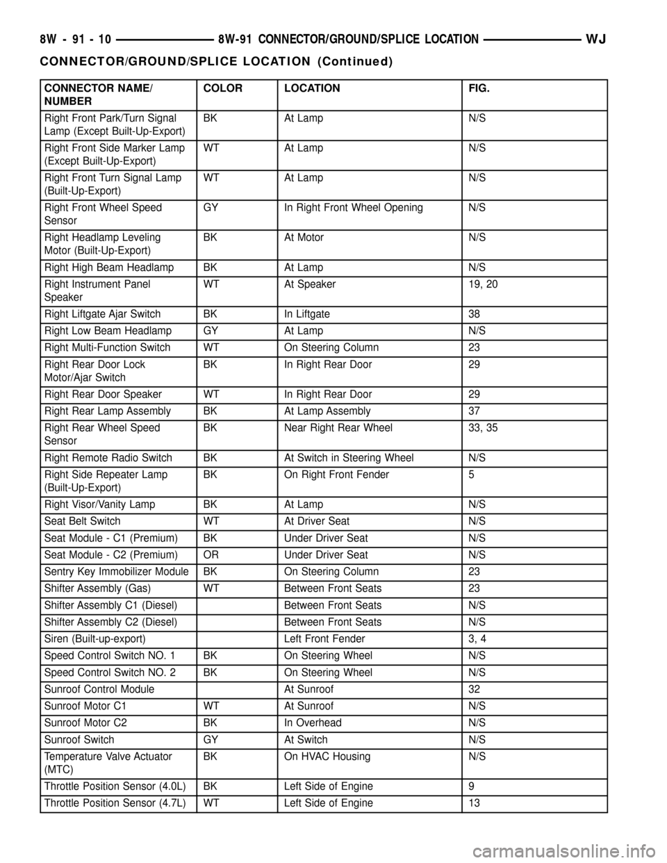
Sentry Key Immobilizer Module BK On Steering Column 23
Shifter Assembly (Gas) WT Between Front Seats 23
Shifter Assembly C1 (Diesel) Between Front Seats N/S
Shifter Assembly C2 (Diesel) Between Front Seats N/S
Siren (Built-up-export) Left Front Fender 3, 4
Speed Control Switch NO. 1 BK On Steering Wheel N/S
Speed Control Switch NO. 2 BK On Steering Wheel N/S
Sunroof Control Module At Sunroof 32
Sunroof Motor C1 WT At Sunroof N/S
Sunroof Motor C2 BK In Overhead N/S
Sunroof Switch GY At Switch N/S
Temperature Valve Actuator
(MTC)BK On HVAC Housing N/S
Throttle Position Sensor (4.0L) BK Left Side of Engine 9
Throttle Position Sensor (4.7L) WT Left Side of Engine 13
8W - 91 - 10 8W-91 CONNECTOR/GROUND/SPLICE LOCATIONWJ
CONNECTOR/GROUND/SPLICE LOCATION (Continued)
Page 1911 of 2199
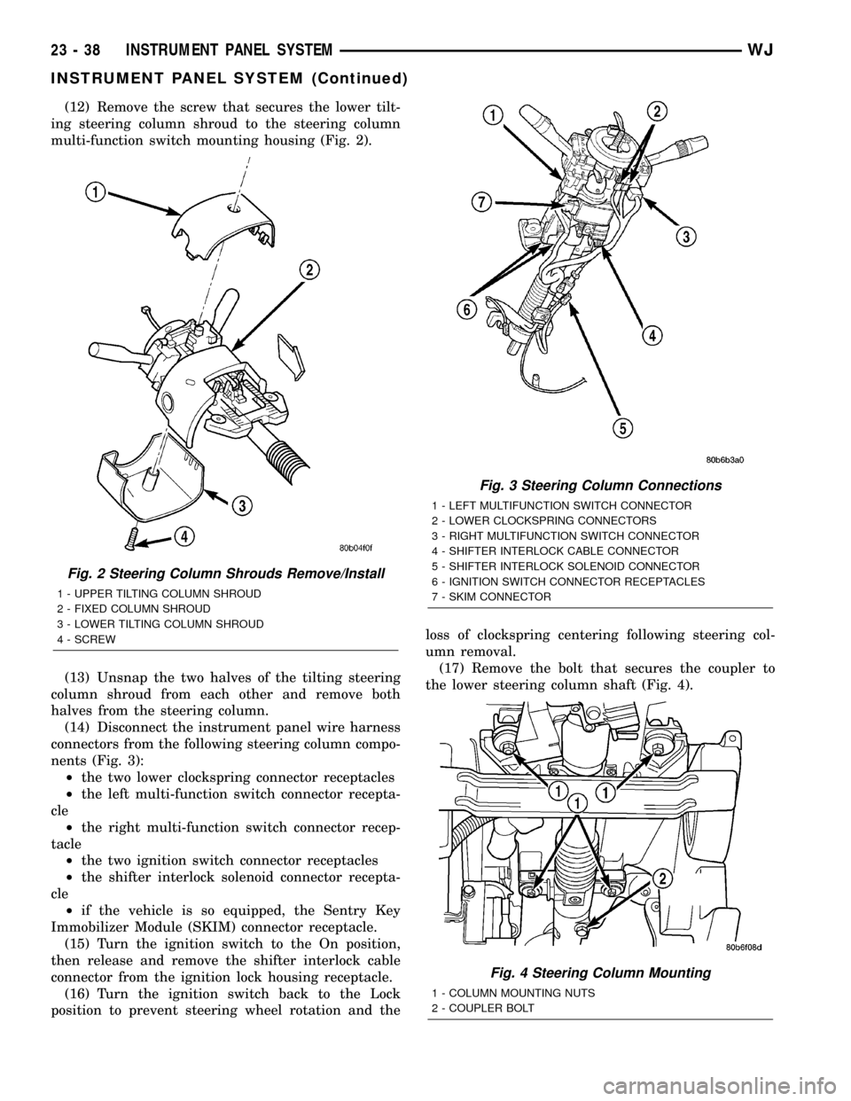
(12) Remove the screw that secures the lower tilt-
ing steering column shroud to the steering column
multi-function switch mounting housing (Fig. 2).
(13) Unsnap the two halves of the tilting steering
column shroud from each other and remove both
halves from the steering column.
(14) Disconnect the instrument panel wire harness
connectors from the following steering column compo-
nents (Fig. 3):
²the two lower clockspring connector receptacles
²the left multi-function switch connector recepta-
cle
²the right multi-function switch connector recep-
tacle
²the two ignition switch connector receptacles
²the shifter interlock solenoid connector recepta-
cle
²if the vehicle is so equipped, the Sentry Key
Immobilizer Module (SKIM) connector receptacle.
(15) Turn the ignition switch to the On position,
then release and remove the shifter interlock cable
connector from the ignition lock housing receptacle.
(16) Turn the ignition switch back to the Lock
position to prevent steering wheel rotation and theloss of clockspring centering following steering col-
umn removal.
(17) Remove the bolt that secures the coupler to
the lower steering column shaft (Fig. 4).
Fig. 2 Steering Column Shrouds Remove/Install
1 - UPPER TILTING COLUMN SHROUD
2 - FIXED COLUMN SHROUD
3 - LOWER TILTING COLUMN SHROUD
4 - SCREW
Fig. 3 Steering Column Connections
1 - LEFT MULTIFUNCTION SWITCH CONNECTOR
2 - LOWER CLOCKSPRING CONNECTORS
3 - RIGHT MULTIFUNCTION SWITCH CONNECTOR
4 - SHIFTER INTERLOCK CABLE CONNECTOR
5 - SHIFTER INTERLOCK SOLENOID CONNECTOR
6 - IGNITION SWITCH CONNECTOR RECEPTACLES
7 - SKIM CONNECTOR
Fig. 4 Steering Column Mounting
1 - COLUMN MOUNTING NUTS
2 - COUPLER BOLT
23 - 38 INSTRUMENT PANEL SYSTEMWJ
INSTRUMENT PANEL SYSTEM (Continued)
Page 1917 of 2199

(23) Reconnect the instrument panel wire harness
connectors to the following floor panel transmission
tunnel components:
²the Airbag Control Module (ACM) connector
receptacle
²the park brake switch terminal
²the transmission shifter connector receptacle.
(24) Reconnect the left and right body wire har-
ness connectors, the Ignition Off Draw (IOD) wire
harness connector and the fused B(+) wire harness
connector to the connector receptacles of the Junction
Block (JB) and tighten the connector screws (Fig. 5).
Tighten the screws to 4 N´m (36 in. lbs.).
(25) Engage the lower steering column shaft with
the steering shaft coupler and position the steering
column to the mounting studs on the instrument
panel steering column support bracket (Fig. 4).
(26) Install and tighten the four nuts that secure
the steering column to the studs on the instrument
panel steering column support bracket. Tighten the
nuts to 11.8 N´m (105 in. lbs.).
(27) Install and tighten the bolt that secures the
coupler to the lower steering column shaft. Tighten
the bolt to 49 N´m (36 ft. lbs.).
(28) Turn the ignition switch to the On position,
then install the shifter interlock cable connector into
the ignition lock housing receptacle.
(29) Reconnect the instrument panel wire harness
connectors to the following steering column compo-
nents (Fig. 3):
²the two lower clockspring connector receptacles
²the left multi-function switch connector recepta-
cle
²the right multi-function switch connector recep-
tacle
²the two ignition switch connector receptacles
²the shifter interlock solenoid connector recepta-
cle
²if the vehicle is so equipped, the Sentry Key
Immobilizer Module (SKIM) connector receptacle.
(30) Position the lower tilting steering column
shroud to the steering column multi-function switchmounting housing, then install and tighten the screw
that secures the shroud to the housing (Fig. 2).
Tighten the screw to 1.9 N´m (17 in. lbs.).
(31) Position the upper tilting steering column
shroud over the steering column. Align the upper and
lower shrouds with each other and snap the two
halves together.
(32) Reinstall the steering column bracket onto the
instrument panel steering column support bracket.
(Refer to 23 - BODY/INSTRUMENT PANEL/IP
STEERING COLUMN BRACKET - INSTALLA-
TION).
(33) Reinstall the steering column opening cover
onto the instrument panel. (Refer to 23 - BODY/IN-
STRUMENT PANEL/STEERING COLUMN OPEN-
ING COVER - INSTALLATION).
(34) Reinstall the cluster bezel onto the instru-
ment panel. (Refer to 23 - BODY/INSTRUMENT
PANEL/CLUSTER BEZEL - INSTALLATION).
(35) Reinstall the fuse cover onto the Junction
Block (JB). (Refer to 8 - ELECTRICAL/POWER DIS-
TRIBUTION/FUSE COVER - INSTALLATION).
(36) Reinstall the console onto the floor panel
transmission tunnel. (Refer to 23 - BODY/INTERI-
OR/FLOOR CONSOLE - INSTALLATION).
(37) Reinstall the trim panels onto the right and
left inner cowl sides. (Refer to 23 - BODY/INTERI-
OR/COWL TRIM - INSTALLATION).
(38) Reinstall the scuff plates onto the right and
left front door sills. (Refer to 23 - BODY/INTERIOR/
DOOR SILL SCUFF PLATE - INSTALLATION).
(39) Reinstall the top cover onto the instrument
panel. (Refer to 23 - BODY/INSTRUMENT PANEL/
INSTRUMENT PANEL TOP COVER - INSTALLA-
TION).
(40) Reinstall the trim onto the right and left
A-pillars. (Refer to 23 - BODY/INTERIOR/A-PILLAR
TRIM - INSTALLATION).
(41) Reconnect the battery negative cable.
23 - 44 INSTRUMENT PANEL SYSTEMWJ
INSTRUMENT PANEL SYSTEM (Continued)