length JEEP GRAND CHEROKEE 2002 WJ / 2.G Owner's Manual
[x] Cancel search | Manufacturer: JEEP, Model Year: 2002, Model line: GRAND CHEROKEE, Model: JEEP GRAND CHEROKEE 2002 WJ / 2.GPages: 2199, PDF Size: 76.01 MB
Page 622 of 2199
formations that grip the wiper blade element. Also
included in this unit is the latching, molded plastic
pivot block that secures the superstructure to the
wiper arm. All of the metal components of the wiper
blade have a satin black finish applied.
²Element- The wiper element or squeegee is the
resilient rubber member of the wiper blade that con-
tacts the glass.
²Flexor- The flexor is a rigid metal component
running along the length of each side of the wiper
element where it is gripped by the claws of the
superstructure.
All Grand Cherokee models have two 52.50 centi-
meter (20.67 inch) long windshield wiper blades with
non-replaceable rubber elements (squeegees). The
wiper blades cannot be adjusted or repaired. If faulty,
worn, or damaged the entire wiper blade unit must
be replaced.
OPERATION
The wiper blades are moved back and forth across
the glass by the wiper arms when the wipers are
being operated. The wiper blade superstructure is
the flexible frame that grips the wiper blade element
and evenly distributes the force of the spring-loaded
wiper arm along the length of the element. The com-
bination of the wiper arm force and the flexibility of
the superstructure makes the element conform to
and maintain proper contact with the glass, even as
the blade is moved over the varied curvature found
across the glass surface. The wiper element flexor
provides the claws of the blade superstructure with a
rigid, yet flexible component on the element which
can be gripped. The rubber element is designed to be
stiff enough to maintain an even cleaning edge as it
is drawn across the glass, but resilient enough to
conform to the glass surface and flip from one clean-
ing edge to the other each time the wiper blade
changes directions.
REMOVAL
NOTE: The notched retainer end of the wiper ele-
ment should always be oriented towards the end of
the wiper blade that is nearest to the wiper pivot.
(1) Lift the front wiper arm to raise the wiper
blade and element off of the glass, until the wiper
arm hinge is in its over-center position.
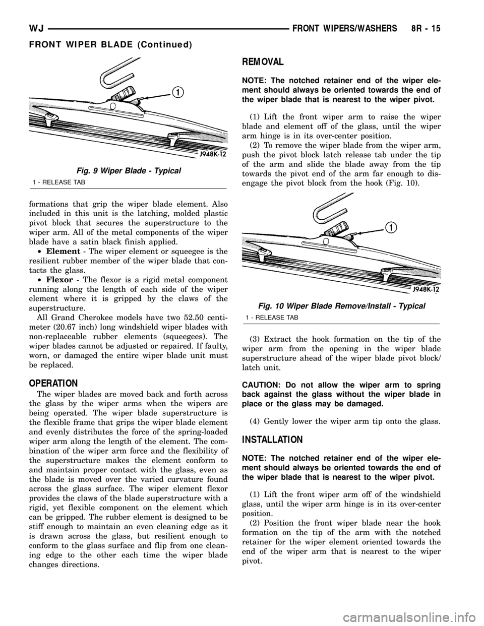
(2) To remove the wiper blade from the wiper arm,
push the pivot block latch release tab under the tip
of the arm and slide the blade away from the tip
towards the pivot end of the arm far enough to dis-
engage the pivot block from the hook (Fig. 10).
(3) Extract the hook formation on the tip of the
wiper arm from the opening in the wiper blade
superstructure ahead of the wiper blade pivot block/
latch unit.
CAUTION: Do not allow the wiper arm to spring
back against the glass without the wiper blade in
place or the glass may be damaged.
(4) Gently lower the wiper arm tip onto the glass.
INSTALLATION
NOTE: The notched retainer end of the wiper ele-
ment should always be oriented towards the end of
the wiper blade that is nearest to the wiper pivot.
(1) Lift the front wiper arm off of the windshield
glass, until the wiper arm hinge is in its over-center
position.
(2) Position the front wiper blade near the hook
formation on the tip of the arm with the notched
retainer for the wiper element oriented towards the
end of the wiper arm that is nearest to the wiper
pivot.
Fig. 9 Wiper Blade - Typical
1 - RELEASE TAB
Fig. 10 Wiper Blade Remove/Install - Typical
1 - RELEASE TAB
WJFRONT WIPERS/WASHERS 8R - 15
FRONT WIPER BLADE (Continued)
Page 646 of 2199
along the left roof side rail to the rear of the vehicle.
At the rear of the vehicle, the headliner hose is
routed above the headliner and along the upper lift-
gate opening panel toward the right side of the vehi-
cle. The headliner hose then passes through a hole
with a rubber grommet in the upper liftgate opening
panel and through another hole with a rubber grom-
met into the upper inner liftgate panel to the rear
washer nozzle.
Washer hose is available for service only as roll
stock, which must then be cut to length. The head-
liner washer hose is integral to the headliner unit
and, if faulty or damaged, the headliner unit must be
replaced. The molded plastic washer hose fittings
cannot be repaired. If these fittings are faulty or
damaged, they must be replaced.
OPERATION
Washer fluid in the washer reservoir is pressurized
and fed by the rear washer pump/motor through the
rear washer system plumbing and fittings to the rear
washer nozzle on the liftgate outer panel above the
liftgate glass. Whenever routing the washer hose or a
wire harness containing a washer hose, it must be
routed away from hot, sharp, or moving parts; and,
sharp bends that might pinch the hose must be
avoided.
REAR WASHER NOZZLE
DESCRIPTION
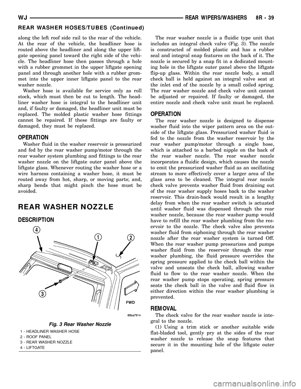
The rear washer nozzle is a fluidic type unit that
includes an integral check valve (Fig. 3). The nozzle
is constructed of molded plastic and has a rubber
seal and integral snap features on the back of it. The
nozzle is secured by a snap fit in a dedicated mount-
ing hole in the liftgate outer panel above the liftgate
flip-up glass. Within the rear nozzle body, a small
check ball is held against an integral valve seat at
the inlet end of the nozzle by a small coiled spring.
The rear washer nozzle and check valve unit cannot
be adjusted or repaired. If faulty or damaged, the
entire nozzle and check valve unit must be replaced.
OPERATION
The rear washer nozzle is designed to dispense
washer fluid into the wiper pattern area on the out-
side of the liftgate glass. Pressurized washer fluid is
fed to the nozzle from the washer reservoir by the
rear washer pump/motor through a single hose,
which is attached to a barbed nipple on the back of
the rear washer nozzle. The rear washer nozzle
incorporates a fluidic design, which causes the nozzle
to emit the pressurized washer fluid as an oscillating
stream to more effectively cover a larger area of the
glass area to be cleaned. The integral rear nozzle
check valve prevents washer fluid from draining out
of the rear washer supply hoses back to the washer
reservoir. This drain-back would result in a lengthy
delay from when the rear washer switch is actuated
until washer fluid was dispensed through the rear
washer nozzle, because the rear washer pump would
have to refill the rear washer plumbing from the res-
ervoir to the nozzle. The check valve also prevents
washer fluid from siphoning through the rear washer
nozzle after the rear washer system is turned Off.
When the rear washer pump pressurizes and pumps
washer fluid from the reservoir through the rear
washer plumbing, the fluid pressure overrides the
spring pressure applied to the check ball within the
valve and unseats the check ball, allowing washer
fluid to flow to the rear washer nozzle. When the
rear washer pump stops operating, spring pressure
seats the check ball in the valve and fluid flow in
either direction within the rear washer plumbing is
prevented.
REMOVAL
The check valve for the rear washer nozzle is inte-
gral to the nozzle.
(1) Using a trim stick or another suitable wide
flat-bladed tool, gently pry at the sides of the rear
washer nozzle to release the snap features that
secure it in the mounting hole of the liftgate outer
panel.
Fig. 3 Rear Washer Nozzle
1 - HEADLINER WASHER HOSE
2 - ROOF PANEL
3 - REAR WASHER NOZZLE
4 - LIFTGATE
WJREAR WIPERS/WASHERS 8R - 39
REAR WASHER HOSES/TUBES (Continued)
Page 650 of 2199
(1) The rear wiper arm must be indexed to the
motor output shaft with the rear wiper motor in the
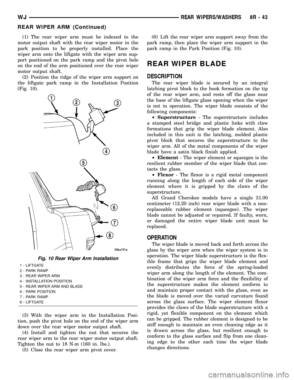
park position to be properly installed. Place the
wiper arm onto the liftgate with the wiper arm sup-
port positioned on the park ramp and the pivot hole
on the end of the arm positioned over the rear wiper
motor output shaft.
(2) Position the ridge of the wiper arm support on
the liftgate park ramp in the Installation Position
(Fig. 10).
(3) With the wiper arm in the Installation Posi-
tion, push the pivot hole on the end of the wiper arm
down over the rear wiper motor output shaft.
(4) Install and tighten the nut that secures the
rear wiper arm to the rear wiper motor output shaft.
Tighten the nut to 18 N´m (160 in. lbs.).
(5) Close the rear wiper arm pivot cover.(6) Lift the rear wiper arm support away from the
park ramp, then place the wiper arm support in the
park ramp in the Park Position (Fig. 10).
REAR WIPER BLADE
DESCRIPTION
The rear wiper blade is secured by an integral
latching pivot block to the hook formation on the tip
of the rear wiper arm, and rests off the glass near
the base of the liftgate glass opening when the wiper
is not in operation. The wiper blade consists of the
following components:
²Superstructure- The superstructure includes
a stamped steel bridge and plastic links with claw
formations that grip the wiper blade element. Also
included in this unit is the latching, molded plastic
pivot block that secures the superstructure to the
wiper arm. All of the metal components of the wiper
blade have a satin black finish applied.
²Element- The wiper element or squeegee is the
resilient rubber member of the wiper blade that con-
tacts the glass.
²Flexor- The flexor is a rigid metal component
running along the length of each side of the wiper
element where it is gripped by the claws of the
superstructure.
All Grand Cherokee models have a single 31.00
centimeter (12.20 inch) rear wiper blade with a non-
replaceable rubber element (squeegee). The wiper
blade cannot be adjusted or repaired. If faulty, worn,
or damaged the entire wiper blade unit must be
replaced.
OPERATION
The wiper blade is moved back and forth across the
glass by the wiper arm when the wiper system is in
operation. The wiper blade superstructure is the flex-
ible frame that grips the wiper blade element and
evenly distributes the force of the spring-loaded
wiper arm along the length of the element. The com-
bination of the wiper arm force and the flexibility of
the superstructure makes the element conform to
and maintain proper contact with the glass, even as
the blade is moved over the varied curvature found
across the glass surface. The wiper element flexor
provides the claws of the blade superstructure with a
rigid, yet flexible component on the element which
can be gripped. The rubber element is designed to be
stiff enough to maintain an even cleaning edge as it
is drawn across the glass, but resilient enough to
conform to the glass surface and flip from one clean-
ing edge to the other each time the wiper blade
changes directions.
Fig. 10 Rear Wiper Arm Installation
1 - LIFTGATE
2 - PARK RAMP
3 - REAR WIPER ARM
4 - INSTALLATION POSITION
5 - REAR WIPER ARM AND BLADE
6 - PARK POSITION
7 - PARK RAMP
8 - LIFTGATE
WJREAR WIPERS/WASHERS 8R - 43
REAR WIPER ARM (Continued)
Page 669 of 2199
DIODE
REMOVAL
(1) Disconnect the battery.
(2) Locate the diode in the harness, and remove
the protective covering.
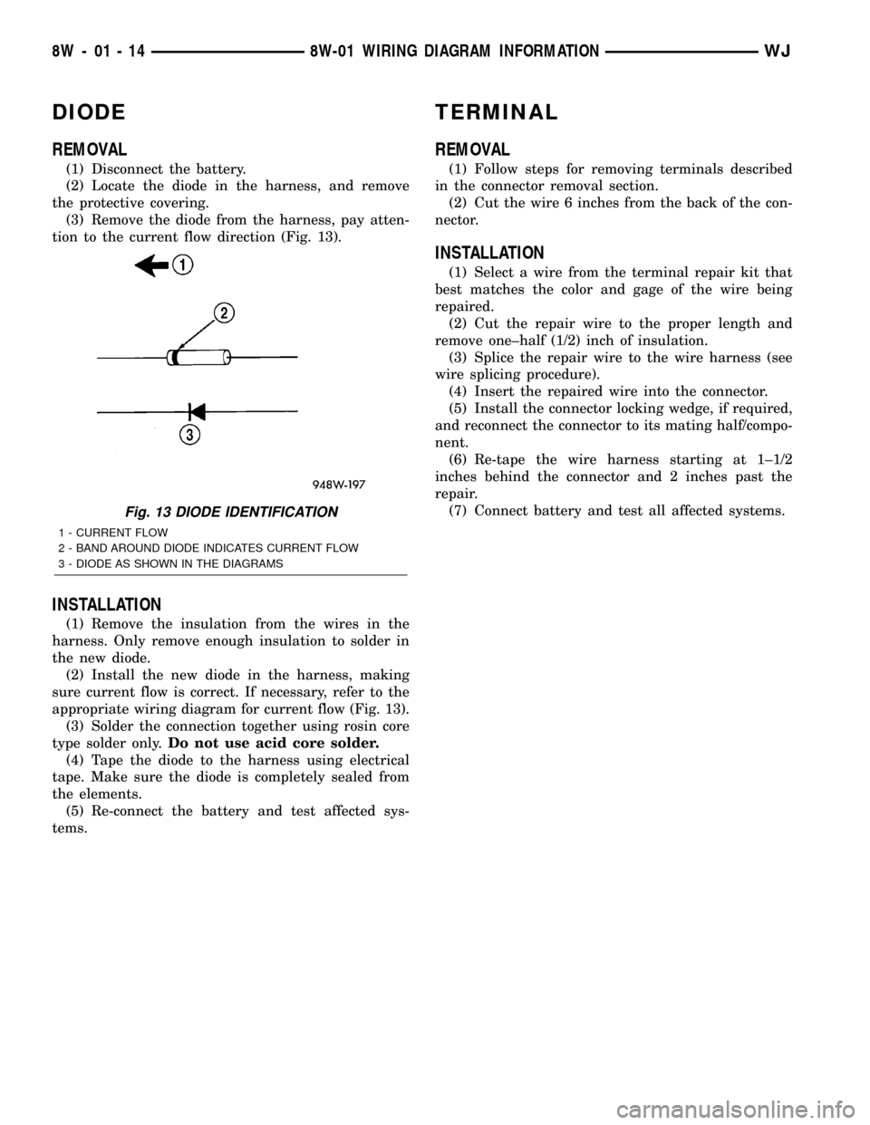
(3) Remove the diode from the harness, pay atten-
tion to the current flow direction (Fig. 13).
INSTALLATION
(1) Remove the insulation from the wires in the
harness. Only remove enough insulation to solder in
the new diode.
(2) Install the new diode in the harness, making
sure current flow is correct. If necessary, refer to the
appropriate wiring diagram for current flow (Fig. 13).
(3) Solder the connection together using rosin core
type solder only.Do not use acid core solder.
(4) Tape the diode to the harness using electrical
tape. Make sure the diode is completely sealed from
the elements.
(5) Re-connect the battery and test affected sys-
tems.
TERMINAL
REMOVAL
(1) Follow steps for removing terminals described
in the connector removal section.
(2) Cut the wire 6 inches from the back of the con-
nector.
INSTALLATION
(1) Select a wire from the terminal repair kit that
best matches the color and gage of the wire being
repaired.
(2) Cut the repair wire to the proper length and
remove one±half (1/2) inch of insulation.
(3) Splice the repair wire to the wire harness (see
wire splicing procedure).
(4) Insert the repaired wire into the connector.
(5) Install the connector locking wedge, if required,
and reconnect the connector to its mating half/compo-
nent.
(6) Re-tape the wire harness starting at 1±1/2
inches behind the connector and 2 inches past the
repair.
(7) Connect battery and test all affected systems.
Fig. 13 DIODE IDENTIFICATION
1 - CURRENT FLOW
2 - BAND AROUND DIODE INDICATES CURRENT FLOW
3 - DIODE AS SHOWN IN THE DIAGRAMS
8W - 01 - 14 8W-01 WIRING DIAGRAM INFORMATIONWJ
Page 1258 of 2199
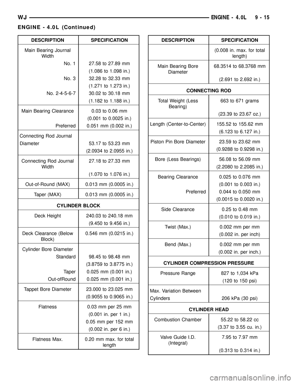
DESCRIPTION SPECIFICATION
Main Bearing Journal
Width
No. 1 27.58 to 27.89 mm
(1.086 to 1.098 in.)
No. 3 32.28 to 32.33 mm
(1.271 to 1.273 in.)
No. 2-4-5-6-7 30.02 to 30.18 mm
(1.182 to 1.188 in.)
Main Bearing Clearance 0.03 to 0.06 mm
(0.001 to 0.0025 in.)
Preferred 0.051 mm (0.002 in.)
Connecting Rod Journal
Diameter 53.17 to 53.23 mm
(2.0934 to 2.0955 in.)
Connecting Rod Journal
Width27.18 to 27.33 mm
(1.070 to 1.076 in.)
Out-of-Round (MAX) 0.013 mm (0.0005 in.)
Taper (MAX) 0.013 mm (0.0005 in.)
CYLINDER BLOCK
Deck Height 240.03 to 240.18 mm
(9.450 to 9.456 in.)
Deck Clearance (Below
Block)0.546 mm (0.0215 in.)
Cylinder Bore Diameter
Standard 98.45 to 98.48 mm
(3.8759 to 3.8775 in.)
Taper 0.025 mm (0.001 in.)
Out-ofRound 0.025 mm (0.001 in.)
Tappet Bore Diameter 23.000 to 23.025 mm
(0.9055 to 0.9065 in.)
Flatness 0.03 mm per 25 mm
(0.001 in. per 1 in.)
0.05 mm per 152 mm
(0.002 in. per 6 in.)
Flatness Max. 0.20 mm max. for total
lengthDESCRIPTION SPECIFICATION
(0.008 in. max. for total
length)
Main Bearing Bore
Diameter68.3514 to 68.3768 mm
(2.691 to 2.692 in.)
CONNECTING ROD
Total Weight (Less
Bearing)663 to 671 grams
(23.39 to 23.67 oz.)
Length (Center-to-Center) 155.52 to 155.62 mm
(6.123 to 6.127 in.)
Piston Pin Bore Diameter 23.59 to 23.62 mm
(0.9288 to 0.9298 in.)
Bore (Less Bearings) 56.08 to 56.09 mm
(2.2080 to 2.2085 in.)
Bearing Clearance 0.025 to 0.076 mm
(0.001 to 0.003 in.)
Preferred 0.044 to 0.050 mm
(0.0015 to 0.0020 in.)
Side Clearance 0.25 to 0.48 mm
(0.010 to 0.019 in.)
Twist (Max.) 0.002 mm per mm
(0.002 in. per inch)
Bend (Max.) 0.002 mm per mm
(0.002 in. per inch.)
CYLINDER COMPRESSION PRESSURE
Pressure Range 827 to 1,034 kPa
(120 to 150 psi)
Max. Variation Between
Cylinders 206 kPa (30 psi)
CYLINDER HEAD
Combustion Chamber 55.22 to 58.22 cc
(3.37 to 3.55 cu. in.)
Valve Guide I.D.
(Integral)7.95 to 7.97 mm
(0.313 to 0.314 in.)
WJENGINE - 4.0L 9 - 15
ENGINE - 4.0L (Continued)
Page 1259 of 2199
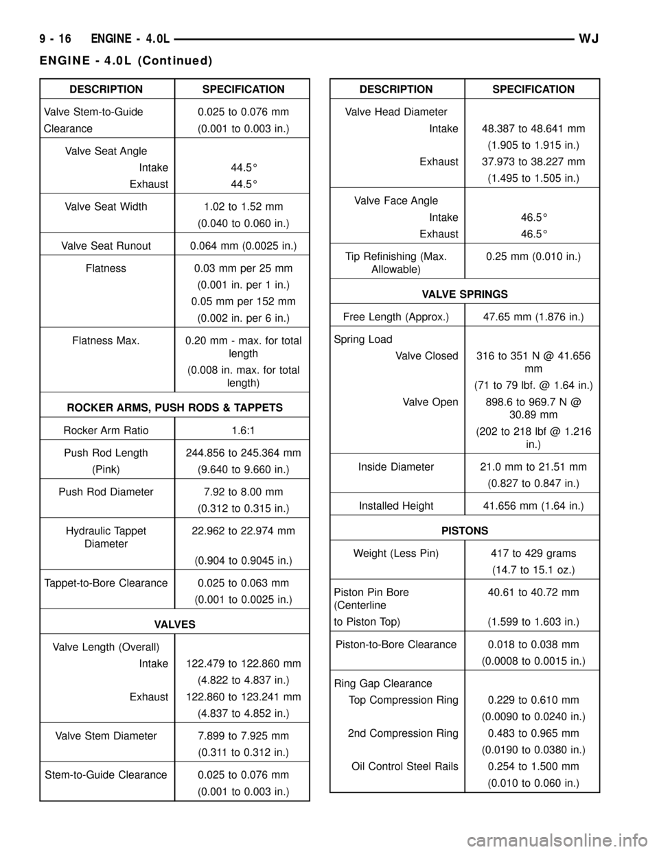
DESCRIPTION SPECIFICATION
Valve Stem-to-Guide 0.025 to 0.076 mm
Clearance (0.001 to 0.003 in.)
Valve Seat Angle
Intake 44.5É
Exhaust 44.5É
Valve Seat Width 1.02 to 1.52 mm
(0.040 to 0.060 in.)
Valve Seat Runout 0.064 mm (0.0025 in.)
Flatness 0.03 mm per 25 mm
(0.001 in. per 1 in.)
0.05 mm per 152 mm
(0.002 in. per 6 in.)
Flatness Max. 0.20 mm - max. for total
length
(0.008 in. max. for total
length)
ROCKER ARMS, PUSH RODS & TAPPETS
Rocker Arm Ratio 1.6:1
Push Rod Length 244.856 to 245.364 mm
(Pink) (9.640 to 9.660 in.)
Push Rod Diameter 7.92 to 8.00 mm
(0.312 to 0.315 in.)
Hydraulic Tappet
Diameter22.962 to 22.974 mm
(0.904 to 0.9045 in.)
Tappet-to-Bore Clearance 0.025 to 0.063 mm
(0.001 to 0.0025 in.)
VA LV E S
Valve Length (Overall)
Intake 122.479 to 122.860 mm
(4.822 to 4.837 in.)
Exhaust 122.860 to 123.241 mm
(4.837 to 4.852 in.)
Valve Stem Diameter 7.899 to 7.925 mm
(0.311 to 0.312 in.)
Stem-to-Guide Clearance 0.025 to 0.076 mm
(0.001 to 0.003 in.)DESCRIPTION SPECIFICATION
Valve Head Diameter
Intake 48.387 to 48.641 mm
(1.905 to 1.915 in.)
Exhaust 37.973 to 38.227 mm
(1.495 to 1.505 in.)
Valve Face Angle
Intake 46.5É
Exhaust 46.5É
Tip Refinishing (Max.
Allowable)0.25 mm (0.010 in.)
VALVE SPRINGS
Free Length (Approx.) 47.65 mm (1.876 in.)
Spring Load
Valve Closed 316 to 351 N @ 41.656
mm
(71 to 79 lbf. @ 1.64 in.)
Valve Open 898.6 to 969.7 N @
30.89 mm
(202 to 218 lbf @ 1.216
in.)
Inside Diameter 21.0 mm to 21.51 mm
(0.827 to 0.847 in.)
Installed Height 41.656 mm (1.64 in.)
PISTONS
Weight (Less Pin) 417 to 429 grams
(14.7 to 15.1 oz.)
Piston Pin Bore
(Centerline40.61 to 40.72 mm
to Piston Top) (1.599 to 1.603 in.)
Piston-to-Bore Clearance 0.018 to 0.038 mm
(0.0008 to 0.0015 in.)
Ring Gap Clearance
Top Compression Ring 0.229 to 0.610 mm
(0.0090 to 0.0240 in.)
2nd Compression Ring 0.483 to 0.965 mm
(0.0190 to 0.0380 in.)
Oil Control Steel Rails 0.254 to 1.500 mm
(0.010 to 0.060 in.)
9 - 16 ENGINE - 4.0LWJ
ENGINE - 4.0L (Continued)
Page 1267 of 2199
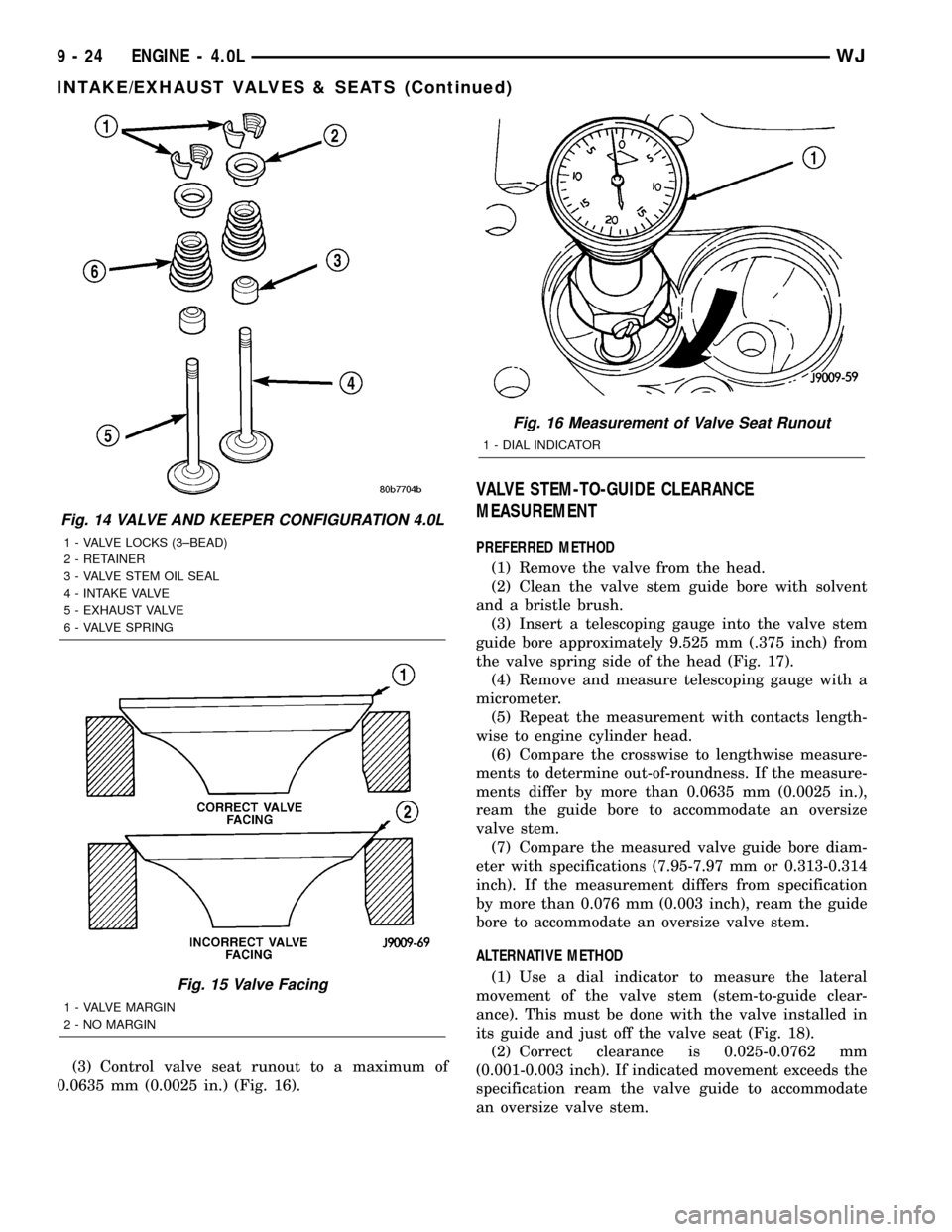
(3) Control valve seat runout to a maximum of
0.0635 mm (0.0025 in.) (Fig. 16).
VALVE STEM-TO-GUIDE CLEARANCE
MEASUREMENT
PREFERRED METHOD
(1) Remove the valve from the head.
(2) Clean the valve stem guide bore with solvent
and a bristle brush.
(3) Insert a telescoping gauge into the valve stem
guide bore approximately 9.525 mm (.375 inch) from
the valve spring side of the head (Fig. 17).
(4) Remove and measure telescoping gauge with a
micrometer.
(5) Repeat the measurement with contacts length-
wise to engine cylinder head.
(6) Compare the crosswise to lengthwise measure-
ments to determine out-of-roundness. If the measure-
ments differ by more than 0.0635 mm (0.0025 in.),
ream the guide bore to accommodate an oversize
valve stem.
(7) Compare the measured valve guide bore diam-
eter with specifications (7.95-7.97 mm or 0.313-0.314
inch). If the measurement differs from specification
by more than 0.076 mm (0.003 inch), ream the guide
bore to accommodate an oversize valve stem.
ALTERNATIVE METHOD
(1) Use a dial indicator to measure the lateral
movement of the valve stem (stem-to-guide clear-
ance). This must be done with the valve installed in
its guide and just off the valve seat (Fig. 18).
(2) Correct clearance is 0.025-0.0762 mm
(0.001-0.003 inch). If indicated movement exceeds the
specification ream the valve guide to accommodate
an oversize valve stem.
Fig. 14 VALVE AND KEEPER CONFIGURATION 4.0L
1 - VALVE LOCKS (3±BEAD)
2 - RETAINER
3 - VALVE STEM OIL SEAL
4 - INTAKE VALVE
5 - EXHAUST VALVE
6 - VALVE SPRING
Fig. 15 Valve Facing
1 - VALVE MARGIN
2 - NO MARGIN
Fig. 16 Measurement of Valve Seat Runout
1 - DIAL INDICATOR
9 - 24 ENGINE - 4.0LWJ
INTAKE/EXHAUST VALVES & SEATS (Continued)
Page 1270 of 2199
INSPECTION
Inspect the pivot surface area of each rocker arm.
Replace any that are scuffed, pitted, cracked or
excessively worn.
Inspect the valve stem tip contact surface of each
rocker arm and replace any rocker arm that is deeply
pitted.
Inspect each push rod end for excessive wear and
replace as required. If any push rod is excessively
worn because of lack of oil, replace it and inspect the
corresponding hydraulic tappet for excessive wear.
Inspect the push rods for straightness by rolling
them on a flat surface or by shining a light between
the push rod and the flat surface.
A wear pattern along the length of the push rod is
not normal. Inspect the engine cylinder head for
obstruction if this condition exists.
INSTALLATION
NOTE: This procedure can be done with the engine
in or out of the vehicle.
(1) Lubricate the ball ends of the push rods with
MopartEngine Oil Supplement, or equivalent and
install push rods in their original locations. Ensurethat the bottom end of each push rod is centered in
the tappet plunger cap seat.
(2) Using MopartEngine Oil Supplement, or
equivalent, lubricate the area of the rocker arm that
the pivot contacts. Install rocker arms, pivots and
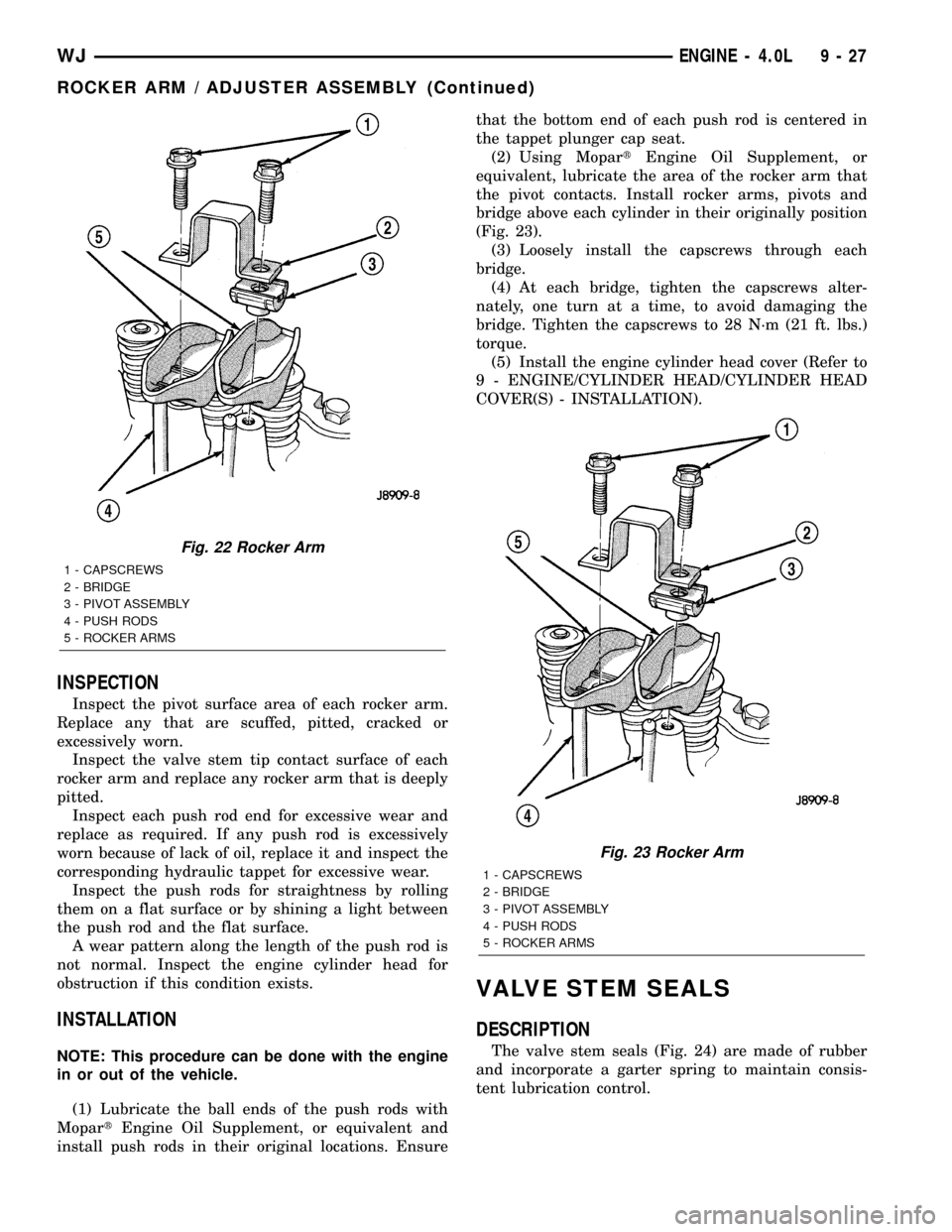
bridge above each cylinder in their originally position
(Fig. 23).
(3) Loosely install the capscrews through each
bridge.
(4) At each bridge, tighten the capscrews alter-
nately, one turn at a time, to avoid damaging the
bridge. Tighten the capscrews to 28 N´m (21 ft. lbs.)
torque.
(5) Install the engine cylinder head cover (Refer to
9 - ENGINE/CYLINDER HEAD/CYLINDER HEAD
COVER(S) - INSTALLATION).
VALVE STEM SEALS
DESCRIPTION
The valve stem seals (Fig. 24) are made of rubber
and incorporate a garter spring to maintain consis-
tent lubrication control.
Fig. 22 Rocker Arm
1 - CAPSCREWS
2 - BRIDGE
3 - PIVOT ASSEMBLY
4 - PUSH RODS
5 - ROCKER ARMS
Fig. 23 Rocker Arm
1 - CAPSCREWS
2 - BRIDGE
3 - PIVOT ASSEMBLY
4 - PUSH RODS
5 - ROCKER ARMS
WJENGINE - 4.0L 9 - 27
ROCKER ARM / ADJUSTER ASSEMBLY (Continued)
Page 1293 of 2199
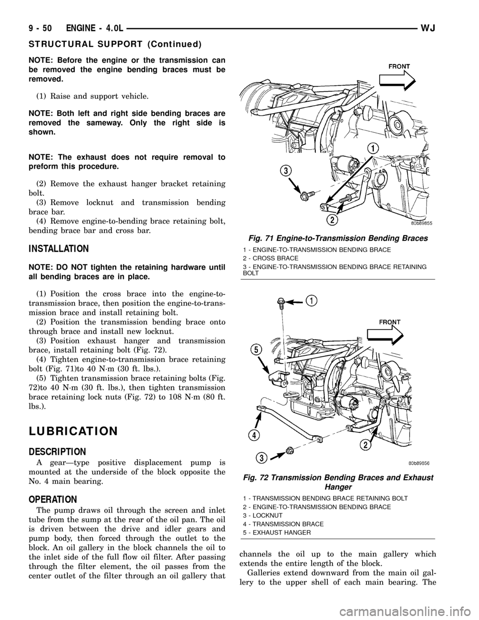
NOTE: Before the engine or the transmission can
be removed the engine bending braces must be
removed.
(1) Raise and support vehicle.
NOTE: Both left and right side bending braces are
removed the sameway. Only the right side is
shown.
NOTE: The exhaust does not require removal to
preform this procedure.
(2) Remove the exhaust hanger bracket retaining
bolt.
(3) Remove locknut and transmission bending
brace bar.
(4) Remove engine-to-bending brace retaining bolt,
bending brace bar and cross bar.
INSTALLATION
NOTE: DO NOT tighten the retaining hardware until
all bending braces are in place.
(1) Position the cross brace into the engine-to-
transmission brace, then position the engine-to-trans-
mission brace and install retaining bolt.
(2) Position the transmission bending brace onto
through brace and install new locknut.
(3) Position exhaust hanger and transmission
brace, install retaining bolt (Fig. 72).
(4) Tighten engine-to-transmission brace retaining
bolt (Fig. 71)to 40 N´m (30 ft. lbs.).
(5) Tighten transmission brace retaining bolts (Fig.
72)to 40 N´m (30 ft. lbs.), then tighten transmission
brace retaining lock nuts (Fig. 72) to 108 N´m (80 ft.
lbs.).
LUBRICATION
DESCRIPTION
A gearÐtype positive displacement pump is
mounted at the underside of the block opposite the
No. 4 main bearing.
OPERATION
The pump draws oil through the screen and inlet
tube from the sump at the rear of the oil pan. The oil
is driven between the drive and idler gears and
pump body, then forced through the outlet to the
block. An oil gallery in the block channels the oil to
the inlet side of the full flow oil filter. After passing
through the filter element, the oil passes from the
center outlet of the filter through an oil gallery thatchannels the oil up to the main gallery which
extends the entire length of the block.
Galleries extend downward from the main oil gal-
lery to the upper shell of each main bearing. The
Fig. 71 Engine-to-Transmission Bending Braces
1 - ENGINE-TO-TRANSMISSION BENDING BRACE
2 - CROSS BRACE
3 - ENGINE-TO-TRANSMISSION BENDING BRACE RETAINING
BOLT
Fig. 72 Transmission Bending Braces and Exhaust
Hanger
1 - TRANSMISSION BENDING BRACE RETAINING BOLT
2 - ENGINE-TO-TRANSMISSION BENDING BRACE
3 - LOCKNUT
4 - TRANSMISSION BRACE
5 - EXHAUST HANGER
9 - 50 ENGINE - 4.0LWJ
STRUCTURAL SUPPORT (Continued)
Page 1319 of 2199
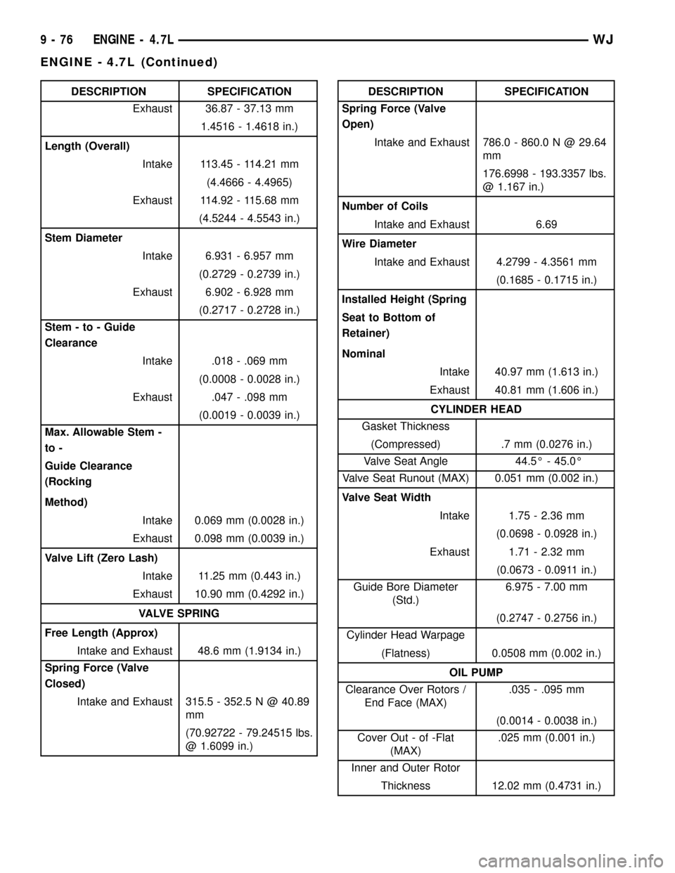
DESCRIPTION SPECIFICATION
Exhaust 36.87 - 37.13 mm
1.4516 - 1.4618 in.)
Length (Overall)
Intake 113.45 - 114.21 mm
(4.4666 - 4.4965)
Exhaust 114.92 - 115.68 mm
(4.5244 - 4.5543 in.)
Stem Diameter
Intake 6.931 - 6.957 mm
(0.2729 - 0.2739 in.)
Exhaust 6.902 - 6.928 mm
(0.2717 - 0.2728 in.)
Stem - to - Guide
Clearance
Intake .018 - .069 mm
(0.0008 - 0.0028 in.)
Exhaust .047 - .098 mm
(0.0019 - 0.0039 in.)
Max. Allowable Stem -
to -
Guide Clearance
(Rocking
Method)
Intake 0.069 mm (0.0028 in.)
Exhaust 0.098 mm (0.0039 in.)
Valve Lift (Zero Lash)
Intake 11.25 mm (0.443 in.)
Exhaust 10.90 mm (0.4292 in.)
VALVE SPRING
Free Length (Approx)
Intake and Exhaust 48.6 mm (1.9134 in.)
Spring Force (Valve
Closed)
Intake and Exhaust 315.5 - 352.5 N @ 40.89
mm
(70.92722 - 79.24515 lbs.
@ 1.6099 in.)DESCRIPTION SPECIFICATION
Spring Force (Valve
Open)
Intake and Exhaust 786.0 - 860.0 N @ 29.64
mm
176.6998 - 193.3357 lbs.
@ 1.167 in.)
Number of Coils
Intake and Exhaust 6.69
Wire Diameter
Intake and Exhaust 4.2799 - 4.3561 mm
(0.1685 - 0.1715 in.)
Installed Height (Spring
Seat to Bottom of
Retainer)
Nominal
Intake 40.97 mm (1.613 in.)
Exhaust 40.81 mm (1.606 in.)
CYLINDER HEAD
Gasket Thickness
(Compressed) .7 mm (0.0276 in.)
Valve Seat Angle 44.5É - 45.0É
Valve Seat Runout (MAX) 0.051 mm (0.002 in.)
Valve Seat Width
Intake 1.75 - 2.36 mm
(0.0698 - 0.0928 in.)
Exhaust 1.71 - 2.32 mm
(0.0673 - 0.0911 in.)
Guide Bore Diameter
(Std.)6.975 - 7.00 mm
(0.2747 - 0.2756 in.)
Cylinder Head Warpage
(Flatness) 0.0508 mm (0.002 in.)
OIL PUMP
Clearance Over Rotors /
End Face (MAX).035 - .095 mm
(0.0014 - 0.0038 in.)
Cover Out - of -Flat
(MAX).025 mm (0.001 in.)
Inner and Outer Rotor
Thickness 12.02 mm (0.4731 in.)
9 - 76 ENGINE - 4.7LWJ
ENGINE - 4.7L (Continued)