seats JEEP GRAND CHEROKEE 2002 WJ / 2.G Owner's Manual
[x] Cancel search | Manufacturer: JEEP, Model Year: 2002, Model line: GRAND CHEROKEE, Model: JEEP GRAND CHEROKEE 2002 WJ / 2.GPages: 2199, PDF Size: 76.01 MB
Page 571 of 2199
INSTALLATION
WARNING: DURING AND FOLLOWING ANY SEAT
BELT SERVICE, CAREFULLY INSPECT ALL SEAT
BELTS, BUCKLES, MOUNTING HARDWARE, AND
RETRACTORS FOR PROPER INSTALLATION,
OPERATION, OR DAMAGE. REPLACE ANY BELT
THAT IS CUT, FRAYED, OR TORN. STRAIGHTEN
ANY BELT THAT IS TWISTED. TIGHTEN ANY
LOOSE FASTENERS. REPLACE ANY BELT THAT
HAS A DAMAGED OR INOPERATIVE BUCKLE OR
RETRACTOR. REPLACE ANY BELT THAT HAS A
BENT OR DAMAGED LATCH PLATE OR ANCHOR
PLATE. NEVER ATTEMPT TO REPAIR A SEAT BELT
COMPONENT. ALWAYS REPLACE DAMAGED OR
FAULTY SEAT BELT COMPONENTS WITH THE COR-
RECT, NEW AND UNUSED REPLACEMENT PARTS
LISTED IN THE MOPAR PARTS CATALOG.
(1) Position the rear center seat belt and retractor
unit onto the seat back panel.
(2) Install and tighten the screw that secures the
retractor to the rear seat back panel (Fig. 35).
Tighten the screw to 43 N´m (32 ft. lbs.).
(3) Position the seat back latch cable plunger
against the retractor latch lever, then engage the
cable fitting into the cable support on the retractor,
which is a light snap fit (Fig. 34).
(4) Route the rear seat belt lower anchor and belt
web guide through the top of the seat back panel.
(5) Reinstall the trim onto the right rear seat
back. (Refer to 23 - BODY/SEATS/SEAT BACK
COVER - REAR - INSTALLATION).
(6) Install and tighten the two screws that secure
the belt web guide to the top of the right rear seat
back panel. Tighten the screws to 2 N´m (20 in. lbs.).
(7) Reinstall the right rear seat back panel into
the vehicle. (Refer to 23 - BODY/SEATS/SEAT BACK
- REAR - INSTALLATION).
(8) Restore the cargo area carpet to the base of the
seat back panel and unfold the right rear seat back
to its upright position.
(9) Position the rear center seat belt lower anchor
to the right rear seat belt buckle unit bracket on the
rear floor panel (Fig. 33).
(10) Install and tighten the screw that secures the
rear center seat belt lower anchor to the right rear
seat belt buckle unit bracket on the rear floor panel.
Tighten the screw to 43 N´m (32 ft. lbs.).
(11) Fold and latch the right rear seat cushion in
its normal seating position.
REAR OUTBOARD SEAT BELT
& RETRACTOR
REMOVAL
WARNING: DURING AND FOLLOWING ANY SEAT
BELT SERVICE, CAREFULLY INSPECT ALL SEAT
BELTS, BUCKLES, MOUNTING HARDWARE, AND
RETRACTORS FOR PROPER INSTALLATION,
OPERATION, OR DAMAGE. REPLACE ANY BELT
THAT IS CUT, FRAYED, OR TORN. STRAIGHTEN
ANY BELT THAT IS TWISTED. TIGHTEN ANY
LOOSE FASTENERS. REPLACE ANY BELT THAT
HAS A DAMAGED OR INOPERATIVE BUCKLE OR
RETRACTOR. REPLACE ANY BELT THAT HAS A
BENT OR DAMAGED LATCH PLATE OR ANCHOR
PLATE. NEVER ATTEMPT TO REPAIR A SEAT BELT
COMPONENT. ALWAYS REPLACE DAMAGED OR
FAULTY SEAT BELT COMPONENTS WITH THE COR-
RECT, NEW AND UNUSED REPLACEMENT PARTS
LISTED IN THE MOPAR PARTS CATALOG.
(1) Disengage the rear seat cushion latch by pull-
ing upward on the release strap.
(2) Fold the rear seat cushion forward against the
back of the front bucket seat.
(3) Remove the screw that secures the rear out-
board seat belt lower anchor to the rear floor panel
(Fig. 36).
(4) Remove the lower anchor from the rear floor
panel.
(5) Using a trim stick or another suitable wide
flat-bladed tool, gently pry the top of the turning loop
trim cover to unsnap it from the height adjuster and
access the screw that secures the rear outboard seat
belt turning loop to the adjuster on the upper C-pil-
lar (Fig. 37).
(6) Remove the screw that secures the seat belt
turning loop to the height adjuster on the upper
C-pillar.
(7) Remove the seat belt turning loop from the
height adjuster.
(8) Remove the trim from the quarter inner panel.
(Refer to 23 - BODY/INTERIOR/QUARTER TRIM
PANEL - REMOVAL).
(9) Remove the screw that secures the retractor to
the mounting tab on the inner and outer rear wheel-
house flange.
(10) Disengage the retractor locator tab from the
slot in the lower C-pillar (Fig. 38).
(11) Remove the rear outboard seat belt and
retractor from the C-pillar as a unit.
8O - 34 RESTRAINTSWJ
REAR CENTER SEAT BELT & RETRACTOR (Continued)
Page 616 of 2199
WASHER SYSTEM
The washer system components should be
inspected periodically, not just when washer perfor-
mance problems are experienced. This inspection
should include the following points:
(1) Check for ice or other foreign material in the
washer reservoir. If contaminated, clean and flush
the washer system. (Refer to 8 - ELECTRICAL/
FRONT WIPERS/WASHERS - CLEANING).
(2) Inspect the washer plumbing for pinched, leak-
ing, deteriorated, or incorrectly routed hoses and
damaged or disconnected hose fittings. Replace dam-
aged or deteriorated hoses and hose fittings. Leaking
washer hoses can sometimes be repaired by cutting
the hose at the leak and splicing it back together
using an in-line connector fitting. Similarly, sections
of deteriorated hose can be cut out and replaced by
splicing in new sections of hose using in-line connec-
tor fittings. Whenever routing a washer hose or a
wire harness containing a washer hose, it must be
routed away from hot, sharp, or moving parts. Also,
sharp bends that might pinch the washer hose must
be avoided.
FRONT CHECK VALVE
DESCRIPTION
A front washer system check valve is standard
equipment on this model. The front check valve is
integral to the front washer nozzle plumbing wye fit-
ting located in the cowl plenum beneath the cowl ple-
num cover/grille panel near the base of the
windshield. The check valve consists of a molded
plastic body with a round center section. Three
barbed hose nipples are formed in a wye configura-
tion on the outside circumference of the center sec-
tion of the valve body. Within the check valve body, a
small check valve operated by a small coiled spring
restricts flow through the unit until the valve is
unseated by a predetermined inlet fluid pressure.
The front check valve cannot be adjusted or repaired
and, if faulty or damaged, it must be replaced.
OPERATION
The front check valve provides more than one func-
tion in this application. It serves as a wye connector
fitting between the cowl grille panel and washer noz-
zle sections of the front washer supply hose. It also
prevents washer fluid from draining out of the front
washer supply hoses back to the washer reservoir.
This drain-back would result in a lengthy delay from
when the front washer switch is actuated until
washer fluid was dispensed through the front washer
nozzles, because the front washer pump would have
to refill the front washer plumbing from the reservoir
to the nozzles. Finally, the front check valve prevents
washer fluid from siphoning through the front
washer nozzles after the front washer system is
turned Off. When the front washer pump pressurizes
and pumps washer fluid from the reservoir through
the front washer plumbing, the fluid pressure over-
rides the spring pressure applied to the check valve
and unseats the valve, allowing washer fluid to flow
toward the front washer nozzles. When the front
washer pump stops operating, spring pressure seats
the check valve and fluid flow in either direction
within the front washer plumbing is prevented.
REMOVAL
(1) Disconnect and isolate the battery negative
cable.
(2) Remove the wiper arms from the wiper pivots.
(Refer to 8 - ELECTRICAL/FRONT WIPERS/WASH-
ERS/FRONT WIPER ARMS - REMOVAL).
(3) Open the hood and pull the hood to plenum
seal off of the forward flanges of the cowl grille cover
and the plenum panel.
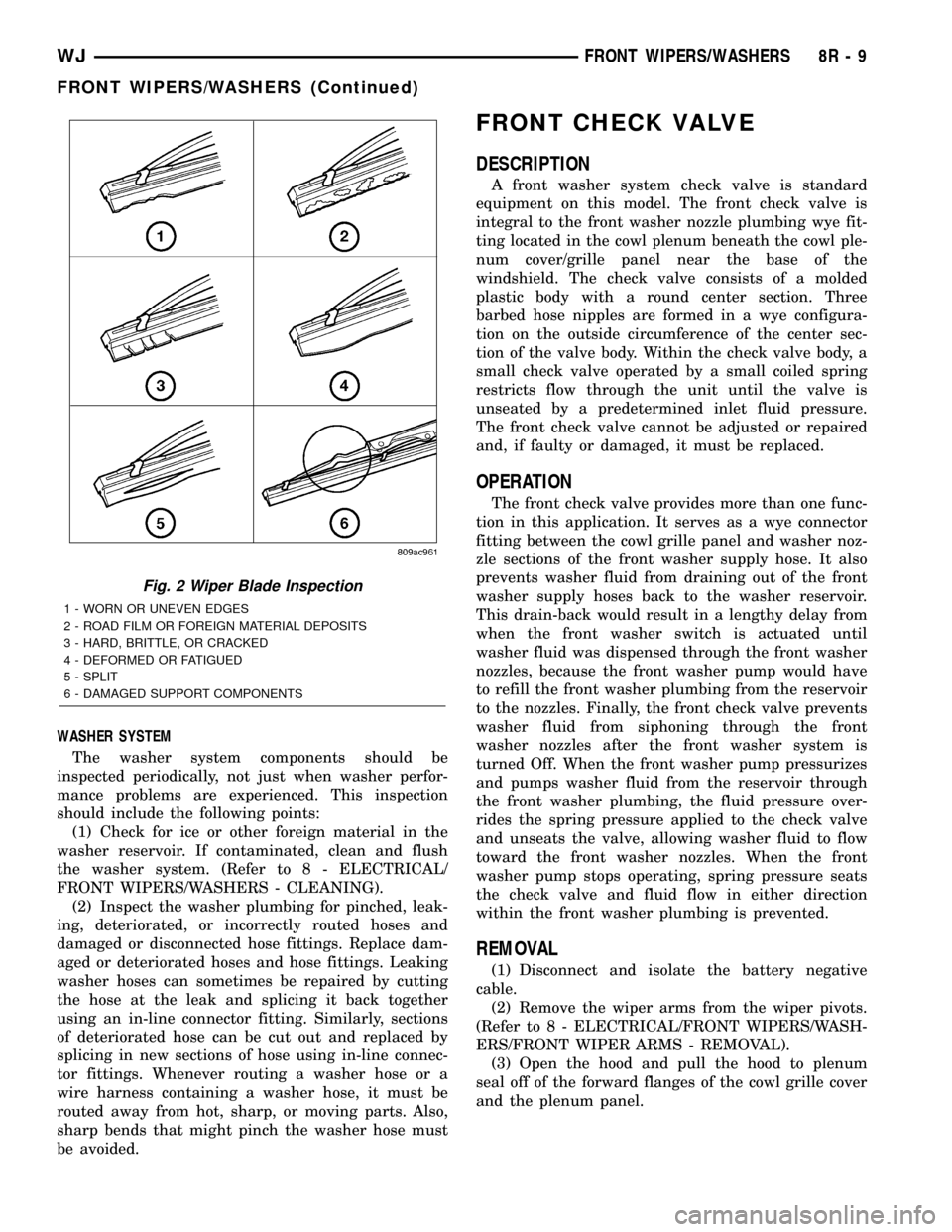
Fig. 2 Wiper Blade Inspection
1 - WORN OR UNEVEN EDGES
2 - ROAD FILM OR FOREIGN MATERIAL DEPOSITS
3 - HARD, BRITTLE, OR CRACKED
4 - DEFORMED OR FATIGUED
5 - SPLIT
6 - DAMAGED SUPPORT COMPONENTS
WJFRONT WIPERS/WASHERS 8R - 9
FRONT WIPERS/WASHERS (Continued)
Page 646 of 2199
along the left roof side rail to the rear of the vehicle.
At the rear of the vehicle, the headliner hose is
routed above the headliner and along the upper lift-
gate opening panel toward the right side of the vehi-
cle. The headliner hose then passes through a hole
with a rubber grommet in the upper liftgate opening
panel and through another hole with a rubber grom-
met into the upper inner liftgate panel to the rear
washer nozzle.
Washer hose is available for service only as roll
stock, which must then be cut to length. The head-
liner washer hose is integral to the headliner unit
and, if faulty or damaged, the headliner unit must be
replaced. The molded plastic washer hose fittings
cannot be repaired. If these fittings are faulty or
damaged, they must be replaced.
OPERATION
Washer fluid in the washer reservoir is pressurized
and fed by the rear washer pump/motor through the
rear washer system plumbing and fittings to the rear
washer nozzle on the liftgate outer panel above the
liftgate glass. Whenever routing the washer hose or a
wire harness containing a washer hose, it must be
routed away from hot, sharp, or moving parts; and,
sharp bends that might pinch the hose must be
avoided.
REAR WASHER NOZZLE
DESCRIPTION
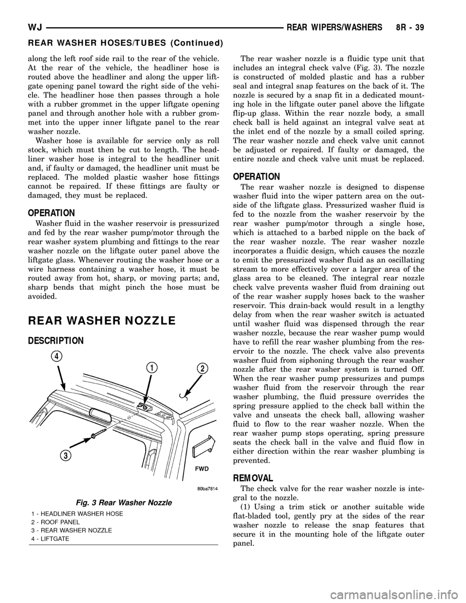
The rear washer nozzle is a fluidic type unit that
includes an integral check valve (Fig. 3). The nozzle
is constructed of molded plastic and has a rubber
seal and integral snap features on the back of it. The
nozzle is secured by a snap fit in a dedicated mount-
ing hole in the liftgate outer panel above the liftgate
flip-up glass. Within the rear nozzle body, a small
check ball is held against an integral valve seat at
the inlet end of the nozzle by a small coiled spring.
The rear washer nozzle and check valve unit cannot
be adjusted or repaired. If faulty or damaged, the
entire nozzle and check valve unit must be replaced.
OPERATION
The rear washer nozzle is designed to dispense
washer fluid into the wiper pattern area on the out-
side of the liftgate glass. Pressurized washer fluid is
fed to the nozzle from the washer reservoir by the
rear washer pump/motor through a single hose,
which is attached to a barbed nipple on the back of
the rear washer nozzle. The rear washer nozzle
incorporates a fluidic design, which causes the nozzle
to emit the pressurized washer fluid as an oscillating
stream to more effectively cover a larger area of the
glass area to be cleaned. The integral rear nozzle
check valve prevents washer fluid from draining out
of the rear washer supply hoses back to the washer
reservoir. This drain-back would result in a lengthy
delay from when the rear washer switch is actuated
until washer fluid was dispensed through the rear
washer nozzle, because the rear washer pump would
have to refill the rear washer plumbing from the res-
ervoir to the nozzle. The check valve also prevents
washer fluid from siphoning through the rear washer
nozzle after the rear washer system is turned Off.
When the rear washer pump pressurizes and pumps
washer fluid from the reservoir through the rear
washer plumbing, the fluid pressure overrides the
spring pressure applied to the check ball within the
valve and unseats the check ball, allowing washer
fluid to flow to the rear washer nozzle. When the
rear washer pump stops operating, spring pressure
seats the check ball in the valve and fluid flow in
either direction within the rear washer plumbing is
prevented.
REMOVAL
The check valve for the rear washer nozzle is inte-
gral to the nozzle.
(1) Using a trim stick or another suitable wide
flat-bladed tool, gently pry at the sides of the rear
washer nozzle to release the snap features that
secure it in the mounting hole of the liftgate outer
panel.
Fig. 3 Rear Washer Nozzle
1 - HEADLINER WASHER HOSE
2 - ROOF PANEL
3 - REAR WASHER NOZZLE
4 - LIFTGATE
WJREAR WIPERS/WASHERS 8R - 39
REAR WASHER HOSES/TUBES (Continued)
Page 654 of 2199

WIRING
TABLE OF CONTENTS
page page
WIRING DIAGRAM INFORMATION....... 8W-01-1
COMPONENT INDEX.................. 8W-02-1
POWER DISTRIBUTION............... 8W-10-1
JUNCTION BLOCK.................... 8W-12-1
GROUND DISTRIBUTION.............. 8W-15-1
BUS COMMUNICATIONS.............. 8W-18-1
CHARGING SYSTEM.................. 8W-20-1
STARTING SYSTEM.................. 8W-21-1
FUEL/IGNITION SYSTEM.............. 8W-30-1
TRANSMISSION CONTROL SYSTEM..... 8W-31-1
VEHICLE SPEED CONTROL............ 8W-33-1
ANTILOCK BRAKES................... 8W-35-1
VEHICLE THEFT SECURITY SYSTEM..... 8W-39-1
INSTRUMENT CLUSTER............... 8W-40-1
HORN/CIGAR LIGHTER/POWER OUTLET . . 8W-41-1
AIR CONDITIONING-HEATER........... 8W-42-1
AIRBAG SYSTEM.................... 8W-43-1
INTERIOR LIGHTING.................. 8W-44-1
BODY CONTROL MODULE............. 8W-45-1AUDIO SYSTEM..................... 8W-47-1
REAR WINDOW DEFOGGER............ 8W-48-1
OVERHEAD CONSOLE................. 8W-49-1
FRONT LIGHTING.................... 8W-50-1
REAR LIGHTING..................... 8W-51-1
TURN SIGNALS...................... 8W-52-1
WIPERS............................ 8W-53-1
TRAILER TOW....................... 8W-54-1
POWER WINDOWS................... 8W-60-1
POWER DOOR LOCKS................ 8W-61-1
POWER MIRRORS................... 8W-62-1
POWER SEATS...................... 8W-63-1
POWER SUNROOF................... 8W-64-1
SPLICE INFORMATION................ 8W-70-1
CONNECTOR PIN-OUT................ 8W-80-1
CONNECTOR/GROUND/SPLICE
LOCATION........................ 8W-91-1
POWER DISTRIBUTION............... 8W-97-1 WJWIRING 8W - 1
Page 672 of 2199

8W-02 COMPONENT INDEX
Component Page
A/C Compressor Clutch................. 8W-42
A/C Pressure Transducer................ 8W-42
Accelerator Pedal Position Sensor......... 8W-30
Accessory Delay Relay.................. 8W-64
Adjustable Pedals..................... 8W-30
Airbags............................. 8W-43
Ambient Temperature Sensor............ 8W-45
Antennas............................ 8W-47
Ash Receiver Lamp.................... 8W-44
Auto Shut Down Relay................. 8W-30
Automatic Day/Night Mirror............. 8W-49
Automatic Headlamp Light Sensor/VTSS
LED.............................. 8W-39
Automatic Zone Control Module.......... 8W-42
Back-Up Lamp Relay................... 8W-51
Battery Temperature Sensor............. 8W-30
Battery............................. 8W-20
Blend Door Motor/Actuator.............. 8W-42
Blower Motor......................... 8W-42
Body Control Module................... 8W-45
Boost Pressure Sensor.................. 8W-30
Brake Lamp Switch.................... 8W-33
Camshaft Position Sensor............... 8W-30
Capacitors........................... 8W-30
Cargo Lamp.......................... 8W-44
Center High Mounted Stop Lamp......... 8W-51
Cigar Lighter......................... 8W-41
Circuit Breakers...................... 8W-12
Clockspring.................. 8W-33, 41, 43, 47
Coil On Plugs......................... 8W-30
Coil Rail............................. 8W-30
Combination Flasher................... 8W-52
Compact Disc Changer.................. 8W-47
Controller Antilock Brake............... 8W-35
Coolant Level Sensor................... 8W-45
Courtesy Lamps....................... 8W-44
Crankcase Heater..................... 8W-30
Crankshaft Position Sensor.............. 8W-30
Cylinder Lock Switches................. 8W-61
Data Link Connector................... 8W-18
Diagnostic Junction Port................ 8W-18
EGR Solenoid......................... 8W-30
Electric Brake........................ 8W-54
Electronic Speed Control Servo........... 8W-33
Engine Control Module................. 8W-30
Engine Coolant Temperature Sensor...... 8W-30
Engine Oil Pressure Sensor.............. 8W-30
Engine Starter Motor................... 8W-21
EVAP/Purge Solenoid................... 8W-30
Fog Lamps........................ 8W-50, 51
Fuel Injectors......................... 8W-30
Fuel Pressure Sensor................... 8W-30Component Page
Fuel Pressure Solenoid................. 8W-30
Fuel Pump........................... 8W-30
Fuel Tank Module..................... 8W-30
Fuses............................ 8W-10, 12
Fusible Link....................... 8W-10, 20
Grounds............................. 8W-15
Generator......................... 8W-20, 30
Glove Box Lamp...................... 8W-44
Glow Plugs........................... 8W-30
Headlamp Leveling Motor............... 8W-50
Heated Seats......................... 8W-63
High Beam Headlamps................. 8W-50
Hood Ajar Switch...................... 8W-39
Horns............................... 8W-41
Hydraulic Cooling Module............ 8W-30, 42
Idle Air Control Motor.................. 8W-30
Ignition Switch....................... 8W-10
Impact Sensors....................... 8W-43
Input Speed Sensor.................... 8W-31
Instrument Cluster.................... 8W-40
Intake Air Temperature Sensor........... 8W-30
Intake Port Swirl Actuator.............. 8W-30
Intrusion Transceiver Module............ 8W-49
Junction Block........................ 8W-12
Knock Sensor......................... 8W-30
Lamp Assemblies................... 8W-51, 52
Leak Detection Pump.................. 8W-30
License Lamps........................ 8W-51
Liftgate............................. 8W-61
Line Pressure Sensor................... 8W-31
Low Beam Headlamps.................. 8W-50
Low Beam Relay...................... 8W-50
Low Beam/Daytime Running Lamp Relay . . . 8W-50
Lumbar Motor........................ 8W-63
Lumbar Switch....................... 8W-63
Manifold Absolute Pressure Sensor........ 8W-30
Manual Temperature Control............. 8W-42
Mass Air Flow Sensor.................. 8W-30
Memory Set Switch................. 8W-62, 63
Mode Door Motor/Actuator............... 8W-42
Multi-Function Switch............... 8W-50, 53
Output Speed Sensor................... 8W-31
Overhead Map/Courtesy Lamp........... 8W-44
Oxygen Sensors....................... 8W-30
Park Brake Switch..................... 8W-40
Park Lamp........................... 8W-50
Park/Neutral Position Switch............ 8W-31
Park/Turn Signal Lamps................ 8W-50
Power Amplifier....................... 8W-47
Power Connector...................... 8W-41
Power Distribution Center............... 8W-10
Power Mirrors........................ 8W-62
WJ8W-02 COMPONENT INDEX 8W - 02 - 1
Page 673 of 2199
Component Page
Power Outlet......................... 8W-41
Power Seats.......................... 8W-63
Power Windows....................... 8W-60
Powertrain Control Module.............. 8W-30
Radio............................... 8W-47
Rain Sensor.......................... 8W-49
Recirculation Door Motor/Actuator........ 8W-42
Red Brake Warning Indicator Switch....... 8W-35
Remote Keyless Module................. 8W-39
Remote Radio Switches................. 8W-47
Splices.............................. 8W-10
Seat Belt Switch...................... 8W-43
Seat Module.......................... 8W-63
Sentry Key Immobilizer Module.......... 8W-39
Shifter Assembly...................... 8W-31
Side Impact Sensors................... 8W-43
Side Marker Lamps.................... 8W-50
Side Repeater Lamps................... 8W-52
Siren............................... 8W-49
Speakers............................ 8W-47Component Page
Speed Control Switches................. 8W-33
Sunroof............................. 8W-64
Temperature Valve Actuator............. 8W-42
Throttle Position Sensor................ 8W-30
Trailer Tow.......................... 8W-54
Transfer Case Position Sensor............ 8W-31
Transmission......................... 8W-31
Turn Signal Lamps.................... 8W-52
Underhood Lamp...................... 8W-44
Vehicle Information Center.............. 8W-49
Viscous/Cabin Heater................... 8W-30
Visor/Vanity Lamps.................... 8W-44
Washer Fluid Level Switch.............. 8W-53
Wastegate Solenoid.................... 8W-30
Water In Fuel Sensor................... 8W-30
Wheel Speed Sensors................... 8W-35
Window Defogger...................... 8W-48
Wiper High/Low Relay.................. 8W-53
Wiper Motor.......................... 8W-53
Washer Pump......................... 8W-5
8W - 02 - 2 8W-02 COMPONENT INDEXWJ
Page 1024 of 2199
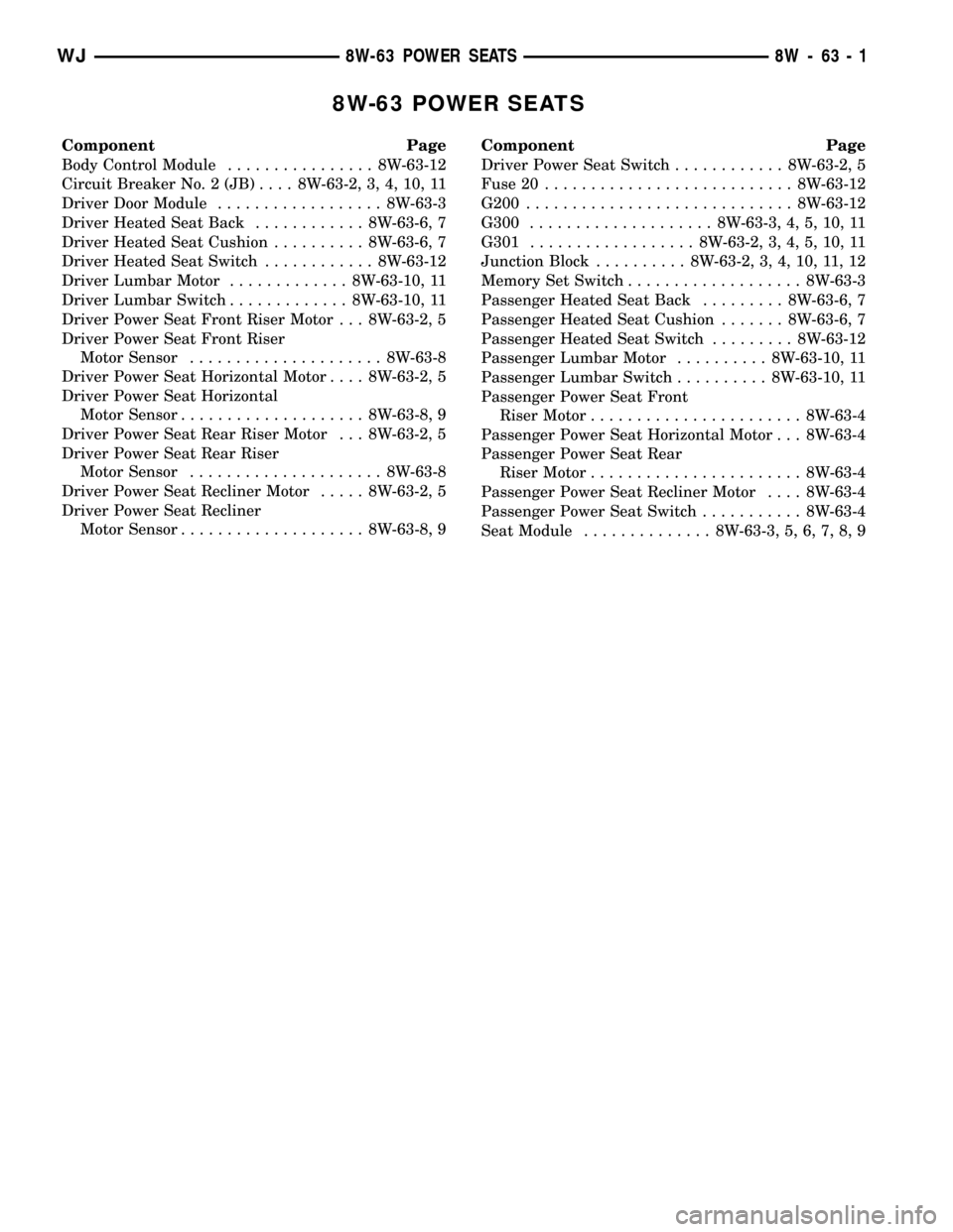
8W-63 POWER SEATS
Component Page
Body Control Module................ 8W-63-12
Circuit Breaker No. 2 (JB).... 8W-63-2, 3, 4, 10, 11
Driver Door Module.................. 8W-63-3
Driver Heated Seat Back............ 8W-63-6, 7
Driver Heated Seat Cushion.......... 8W-63-6, 7
Driver Heated Seat Switch............ 8W-63-12
Driver Lumbar Motor............. 8W-63-10, 11
Driver Lumbar Switch............. 8W-63-10, 11
Driver Power Seat Front Riser Motor . . . 8W-63-2, 5
Driver Power Seat Front Riser
Motor Sensor..................... 8W-63-8
Driver Power Seat Horizontal Motor.... 8W-63-2, 5
Driver Power Seat Horizontal
Motor Sensor.................... 8W-63-8, 9
Driver Power Seat Rear Riser Motor . . . 8W-63-2, 5
Driver Power Seat Rear Riser
Motor Sensor..................... 8W-63-8
Driver Power Seat Recliner Motor..... 8W-63-2, 5
Driver Power Seat Recliner
Motor Sensor.................... 8W-63-8, 9Component Page
Driver Power Seat Switch............ 8W-63-2, 5
Fuse 20........................... 8W-63-12
G200............................. 8W-63-12
G300.................... 8W-63-3, 4, 5, 10, 11
G301.................. 8W-63-2, 3, 4, 5, 10, 11
Junction Block.......... 8W-63-2, 3, 4, 10, 11, 12
Memory Set Switch................... 8W-63-3
Passenger Heated Seat Back......... 8W-63-6, 7
Passenger Heated Seat Cushion....... 8W-63-6, 7
Passenger Heated Seat Switch......... 8W-63-12
Passenger Lumbar Motor.......... 8W-63-10, 11
Passenger Lumbar Switch.......... 8W-63-10, 11
Passenger Power Seat Front
Riser Motor....................... 8W-63-4
Passenger Power Seat Horizontal Motor . . . 8W-63-4
Passenger Power Seat Rear
Riser Motor....................... 8W-63-4
Passenger Power Seat Recliner Motor.... 8W-63-4
Passenger Power Seat Switch........... 8W-63-4
Seat Module.............. 8W-63-3, 5, 6, 7, 8, 9
WJ8W-63 POWER SEATS 8W - 63 - 1
Page 1091 of 2199
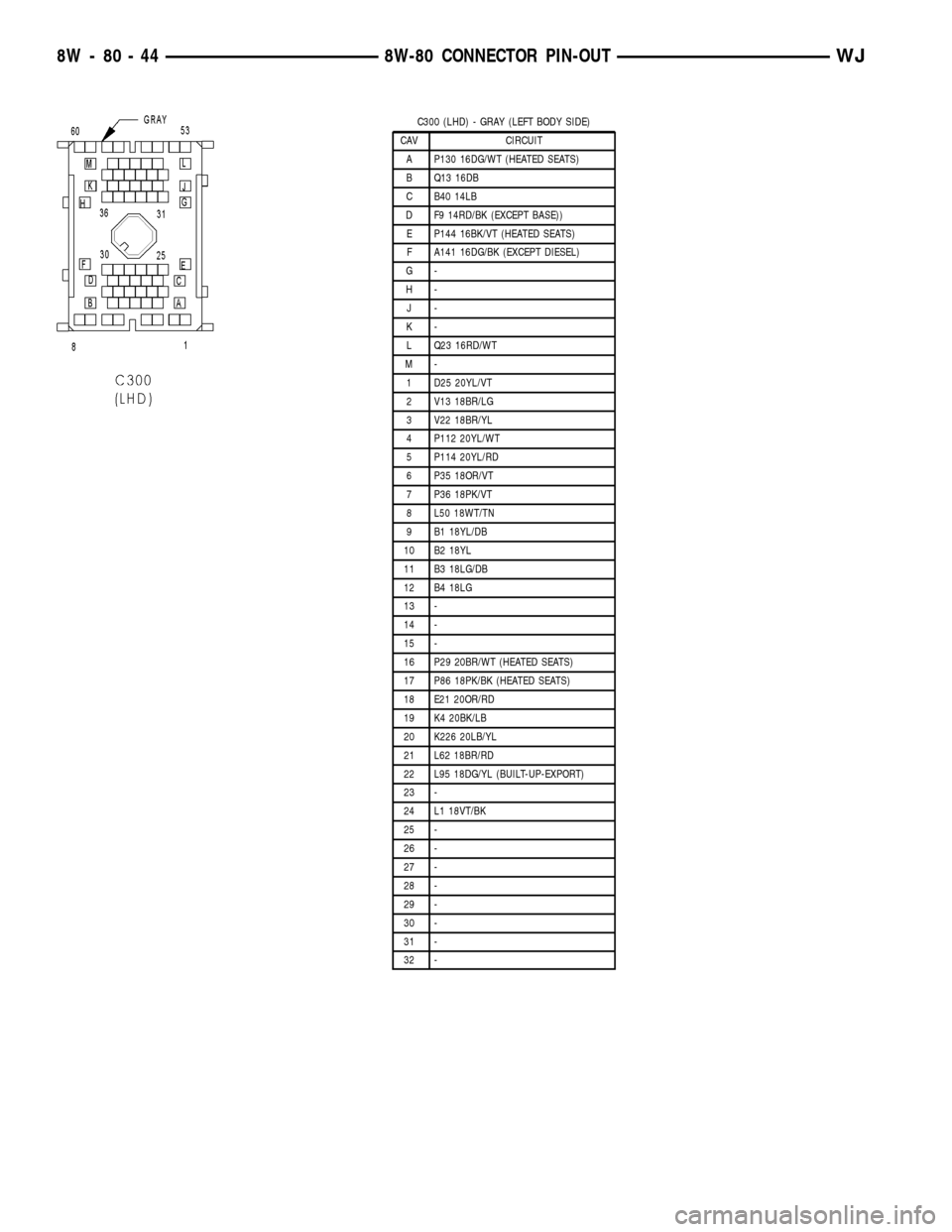
C300 (LHD) - GRAY (LEFT BODY SIDE)
CAV CIRCUIT
A P130 16DG/WT (HEATED SEATS)
B Q13 16DB
C B40 14LB
D F9 14RD/BK (EXCEPT BASE))
E P144 16BK/VT (HEATED SEATS)
F A141 16DG/BK (EXCEPT DIESEL)
G-
H-
J-
K-
L Q23 16RD/WT
M-
1 D25 20YL/VT
2 V13 18BR/LG
3 V22 18BR/YL
4 P112 20YL/WT
5 P114 20YL/RD
6 P35 18OR/VT
7 P36 18PK/VT
8 L50 18WT/TN
9 B1 18YL/DB
10 B2 18YL
11 B3 18LG/DB
12 B4 18LG
13 -
14 -
15 -
16 P29 20BR/WT (HEATED SEATS)
17 P86 18PK/BK (HEATED SEATS)
18 E21 20OR/RD
19 K4 20BK/LB
20 K226 20LB/YL
21 L62 18BR/RD
22 L95 18DG/YL (BUILT-UP-EXPORT)
23 -
24 L1 18VT/BK
25 -
26 -
27 -
28 -
29 -
30 -
31 -
32 -
8W - 80 - 44 8W-80 CONNECTOR PIN-OUTWJ
Page 1098 of 2199
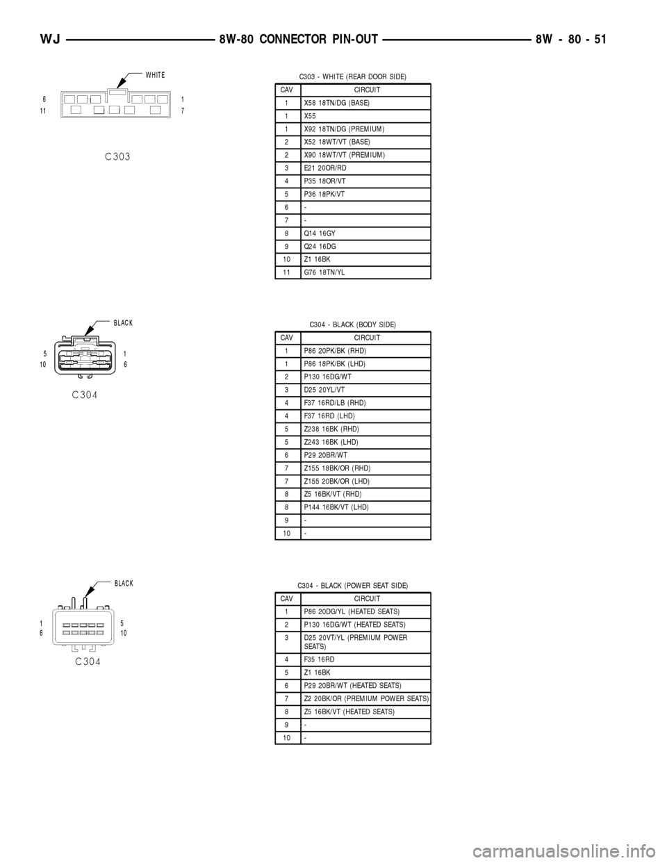
C303 - WHITE (REAR DOOR SIDE)
CAV CIRCUIT
1 X58 18TN/DG (BASE)
1 X55
1 X92 18TN/DG (PREMIUM)
2 X52 18WT/VT (BASE)
2 X90 18WT/VT (PREMIUM)
3 E21 20OR/RD
4 P35 18OR/VT
5 P36 18PK/VT
6-
7-
8 Q14 16GY
9 Q24 16DG
10 Z1 16BK
11 G76 18TN/YL
C304 - BLACK (BODY SIDE)
CAV CIRCUIT
1 P86 20PK/BK (RHD)
1 P86 18PK/BK (LHD)
2 P130 16DG/WT
3 D25 20YL/VT
4 F37 16RD/LB (RHD)
4 F37 16RD (LHD)
5 Z238 16BK (RHD)
5 Z243 16BK (LHD)
6 P29 20BR/WT
7 Z155 18BK/OR (RHD)
7 Z155 20BK/OR (LHD)
8 Z5 16BK/VT (RHD)
8 P144 16BK/VT (LHD)
9-
10 -
C304 - BLACK (POWER SEAT SIDE)
CAV CIRCUIT
1 P86 20DG/YL (HEATED SEATS)
2 P130 16DG/WT (HEATED SEATS)
3 D25 20VT/YL (PREMIUM POWER
SEATS)
4 F35 16RD
5 Z1 16BK
6 P29 20BR/WT (HEATED SEATS)
7 Z2 20BK/OR (PREMIUM POWER SEATS)
8 Z5 16BK/VT (HEATED SEATS)
9-
10 -
WJ8W-80 CONNECTOR PIN-OUT 8W - 80 - 51
Page 1099 of 2199
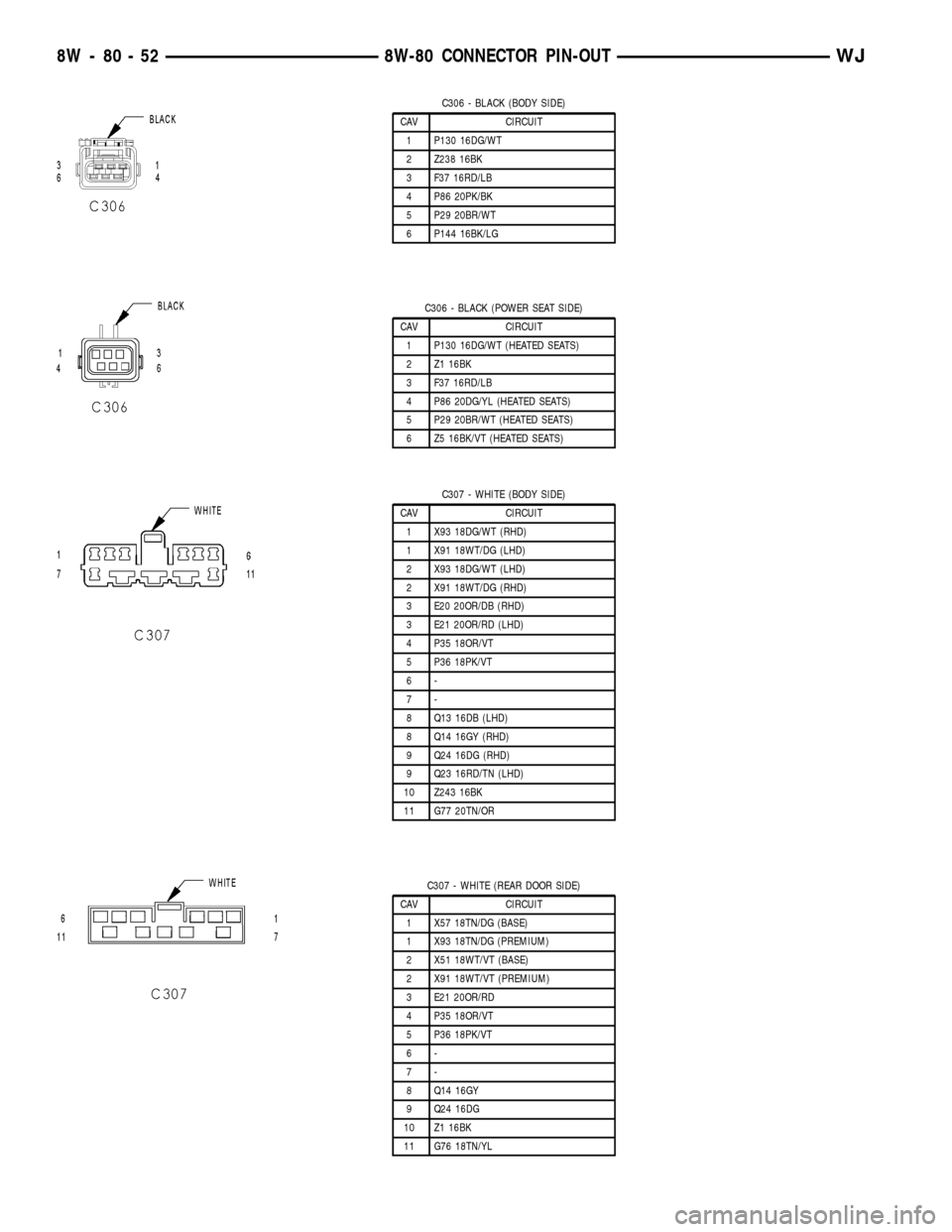
C306 - BLACK (BODY SIDE)
CAV CIRCUIT
1 P130 16DG/WT
2 Z238 16BK
3 F37 16RD/LB
4 P86 20PK/BK
5 P29 20BR/WT
6 P144 16BK/LG
C306 - BLACK (POWER SEAT SIDE)
CAV CIRCUIT
1 P130 16DG/WT (HEATED SEATS)
2 Z1 16BK
3 F37 16RD/LB
4 P86 20DG/YL (HEATED SEATS)
5 P29 20BR/WT (HEATED SEATS)
6 Z5 16BK/VT (HEATED SEATS)
C307 - WHITE (BODY SIDE)
CAV CIRCUIT
1 X93 18DG/WT (RHD)
1 X91 18WT/DG (LHD)
2 X93 18DG/WT (LHD)
2 X91 18WT/DG (RHD)
3 E20 20OR/DB (RHD)
3 E21 20OR/RD (LHD)
4 P35 18OR/VT
5 P36 18PK/VT
6-
7-
8 Q13 16DB (LHD)
8 Q14 16GY (RHD)
9 Q24 16DG (RHD)
9 Q23 16RD/TN (LHD)
10 Z243 16BK
11 G77 20TN/OR
C307 - WHITE (REAR DOOR SIDE)
CAV CIRCUIT
1 X57 18TN/DG (BASE)
1 X93 18TN/DG (PREMIUM)
2 X51 18WT/VT (BASE)
2 X91 18WT/VT (PREMIUM)
3 E21 20OR/RD
4 P35 18OR/VT
5 P36 18PK/VT
6-
7-
8 Q14 16GY
9 Q24 16DG
10 Z1 16BK
11 G76 18TN/YL
8W - 80 - 52 8W-80 CONNECTOR PIN-OUTWJ