BIW JEEP GRAND CHEROKEE 2002 WJ / 2.G Owner's Guide
[x] Cancel search | Manufacturer: JEEP, Model Year: 2002, Model line: GRAND CHEROKEE, Model: JEEP GRAND CHEROKEE 2002 WJ / 2.GPages: 2199, PDF Size: 76.01 MB
Page 121 of 2199
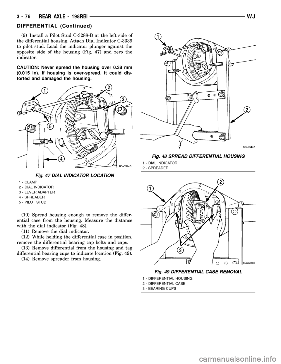
(9) Install a Pilot Stud C-3288-B at the left side of
the differential housing. Attach Dial Indicator C-3339
to pilot stud. Load the indicator plunger against the
opposite side of the housing (Fig. 47) and zero the
indicator.
CAUTION: Never spread the housing over 0.38 mm
(0.015 in). If housing is over-spread, it could dis-
torted and damaged the housing.
(10) Spread housing enough to remove the differ-
ential case from the housing. Measure the distance
with the dial indicator (Fig. 48).
(11) Remove the dial indicator.
(12) While holding the differential case in position,
remove the differential bearing cap bolts and caps.
(13) Remove differential from the housing and tag
differential bearing cups to indicate location (Fig. 49).
(14) Remove spreader from housing.
Fig. 47 DIAL INDICATOR LOCATION
1 - CLAMP
2 - DIAL INDICATOR
3 - LEVER ADAPTER
4 - SPREADER
5 - PILOT STUD
Fig. 48 SPREAD DIFFERENTIAL HOUSING
1 - DIAL INDICATOR
2 - SPREADER
Fig. 49 DIFFERENTIAL CASE REMOVAL
1 - DIFFERENTIAL HOUSING
2 - DIFFERENTIAL CASE
3 - BEARING CUPS
3 - 76 REAR AXLE - 198RBIWJ
DIFFERENTIAL (Continued)
Page 123 of 2199
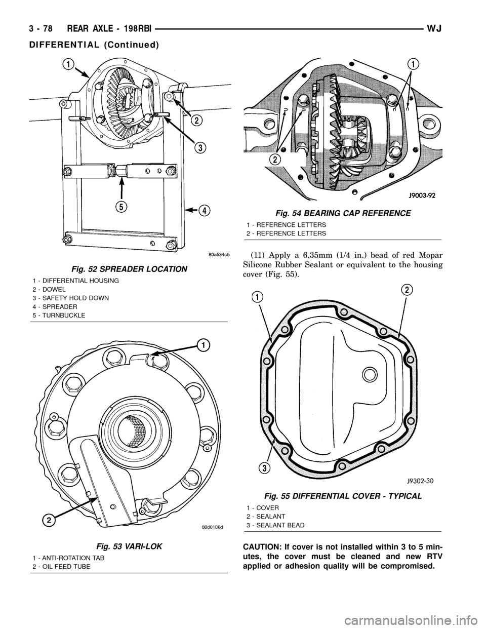
(11) Apply a 6.35mm (1/4 in.) bead of red Mopar
Silicone Rubber Sealant or equivalent to the housing
cover (Fig. 55).
CAUTION: If cover is not installed within 3 to 5 min-
utes, the cover must be cleaned and new RTV
applied or adhesion quality will be compromised.
Fig. 52 SPREADER LOCATION
1 - DIFFERENTIAL HOUSING
2 - DOWEL
3 - SAFETY HOLD DOWN
4 - SPREADER
5 - TURNBUCKLE
Fig. 53 VARI-LOK
1 - ANTI-ROTATION TAB
2 - OIL FEED TUBE
Fig. 54 BEARING CAP REFERENCE
1 - REFERENCE LETTERS
2 - REFERENCE LETTERS
Fig. 55 DIFFERENTIAL COVER - TYPICAL
1 - COVER
2 - SEALANT
3 - SEALANT BEAD
3 - 78 REAR AXLE - 198RBIWJ
DIFFERENTIAL (Continued)
Page 125 of 2199
(2) Remove ring gear if the ring gear is to be
replaced. The Trac-loktdifferential can be serviced
with the ring gear installed.
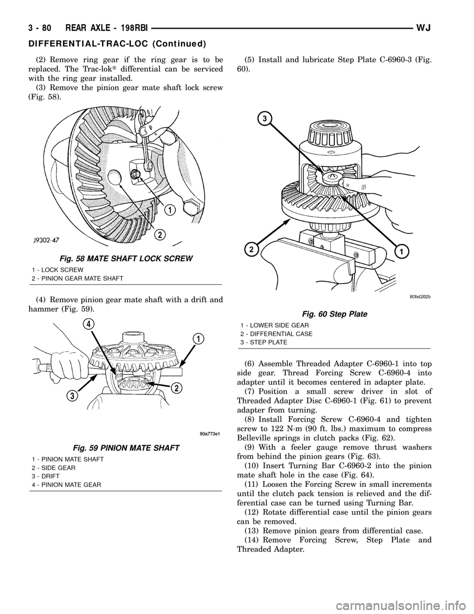
(3) Remove the pinion gear mate shaft lock screw
(Fig. 58).
(4) Remove pinion gear mate shaft with a drift and
hammer (Fig. 59).(5) Install and lubricate Step Plate C-6960-3 (Fig.
60).
(6) Assemble Threaded Adapter C-6960-1 into top
side gear. Thread Forcing Screw C-6960-4 into
adapter until it becomes centered in adapter plate.
(7) Position a small screw driver in slot of
Threaded Adapter Disc C-6960-1 (Fig. 61) to prevent
adapter from turning.
(8) Install Forcing Screw C-6960-4 and tighten
screw to 122 N´m (90 ft. lbs.) maximum to compress
Belleville springs in clutch packs (Fig. 62).
(9) With a feeler gauge remove thrust washers
from behind the pinion gears (Fig. 63).
(10) Insert Turning Bar C-6960-2 into the pinion
mate shaft hole in the case (Fig. 64).
(11) Loosen the Forcing Screw in small increments
until the clutch pack tension is relieved and the dif-
ferential case can be turned using Turning Bar.
(12) Rotate differential case until the pinion gears
can be removed.
(13) Remove pinion gears from differential case.
(14) Remove Forcing Screw, Step Plate and
Threaded Adapter.
Fig. 58 MATE SHAFT LOCK SCREW
1 - LOCK SCREW
2 - PINION GEAR MATE SHAFT
Fig. 59 PINION MATE SHAFT
1 - PINION MATE SHAFT
2 - SIDE GEAR
3 - DRIFT
4 - PINION MATE GEAR
Fig. 60 Step Plate
1 - LOWER SIDE GEAR
2 - DIFFERENTIAL CASE
3 - STEP PLATE
3 - 80 REAR AXLE - 198RBIWJ
DIFFERENTIAL-TRAC-LOC (Continued)
Page 127 of 2199
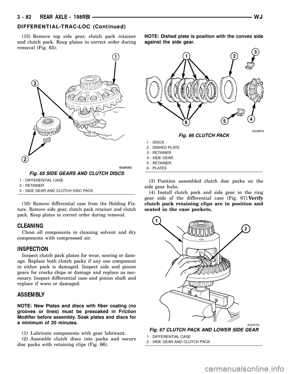
(15) Remove top side gear, clutch pack retainer
and clutch pack. Keep plates in correct order during
removal (Fig. 65).
(16)
Remove differential case from the Holding Fix-
ture. Remove side gear, clutch pack retainer and clutch
pack. Keep plates in correct order during removal.
CLEANING
Clean all components in cleaning solvent and dry
components with compressed air.
INSPECTION
Inspect clutch pack plates for wear, scoring or dam-
age. Replace both clutch packs if any one component
in either pack is damaged. Inspect side and pinion
gears for cracks chips or damage and replace as nec-
essary. Inspect differential case and pinion shaft and
replace if worn or damaged.
ASSEMBLY
NOTE: New Plates and discs with fiber coating (no
grooves or lines) must be presoaked in Friction
Modifier before assembly. Soak plates and discs for
a minimum of 20 minutes.
(1) Lubricate components with gear lubricant.
(2) Assemble clutch discs into packs and secure
disc packs with retaining clips (Fig. 66).NOTE: Dished plate is position with the convex side
against the side gear.
(3) Position assembled clutch disc packs on the
side gear hubs.
(4) Install clutch pack and side gear in the ring
gear side of the differential case (Fig. 67).Verify
clutch pack retaining clips are in position and
seated in the case pockets.
Fig. 65 SIDE GEARS AND CLUTCH DISCS
1 - DIFFERENTIAL CASE
2 - RETAINER
3 - SIDE GEAR AND CLUTCH DISC PACK
Fig. 66 CLUTCH PACK
1 - DISCS
2 - DISHED PLATE
3 - RETAINER
4 - SIDE GEAR
5 - RETAINER
6 - PLATES
Fig. 67 CLUTCH PACK AND LOWER SIDE GEAR
1 - DIFFERENTIAL CASE
2 - SIDE GEAR AND CLUTCH PACK
3 - 82 REAR AXLE - 198RBIWJ
DIFFERENTIAL-TRAC-LOC (Continued)
Page 129 of 2199
INSTALLATION
NOTE: If differential side bearings or differential
case are replaced, differential side bearing shim
requirements may change. Refer to Adjustments
(Differential Bearing Preload and Gear Backlash) for
procedures.
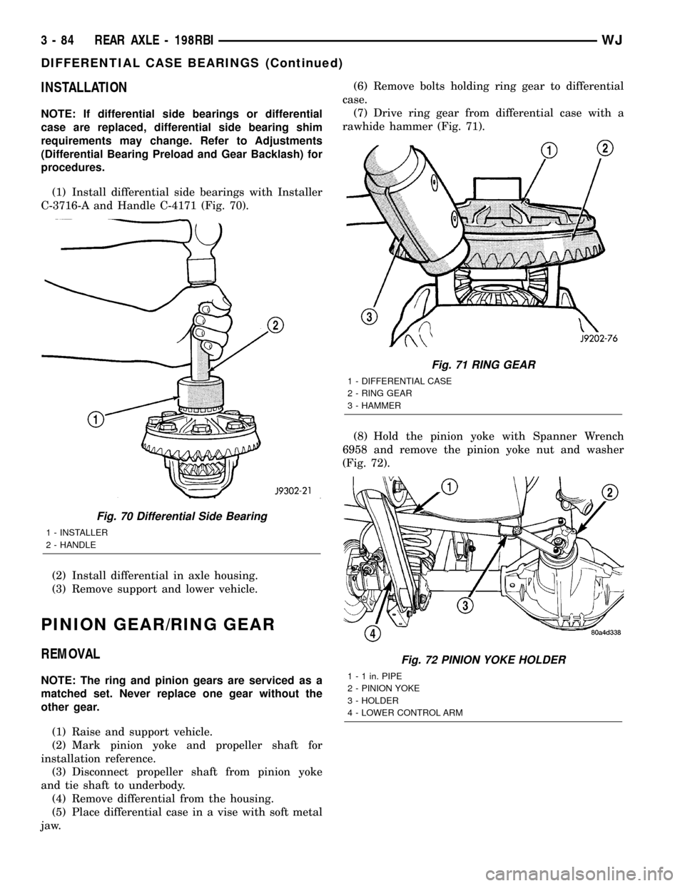
(1) Install differential side bearings with Installer
C-3716-A and Handle C-4171 (Fig. 70).
(2) Install differential in axle housing.
(3) Remove support and lower vehicle.
PINION GEAR/RING GEAR
REMOVAL
NOTE: The ring and pinion gears are serviced as a
matched set. Never replace one gear without the
other gear.
(1) Raise and support vehicle.
(2) Mark pinion yoke and propeller shaft for
installation reference.
(3) Disconnect propeller shaft from pinion yoke
and tie shaft to underbody.
(4) Remove differential from the housing.
(5) Place differential case in a vise with soft metal
jaw.(6) Remove bolts holding ring gear to differential
case.
(7) Drive ring gear from differential case with a
rawhide hammer (Fig. 71).
(8) Hold the pinion yoke with Spanner Wrench
6958 and remove the pinion yoke nut and washer
(Fig. 72).
Fig. 70 Differential Side Bearing
1 - INSTALLER
2 - HANDLE
Fig. 71 RING GEAR
1 - DIFFERENTIAL CASE
2 - RING GEAR
3 - HAMMER
Fig. 72 PINION YOKE HOLDER
1 - 1 in. PIPE
2 - PINION YOKE
3 - HOLDER
4 - LOWER CONTROL ARM
3 - 84 REAR AXLE - 198RBIWJ
DIFFERENTIAL CASE BEARINGS (Continued)
Page 131 of 2199
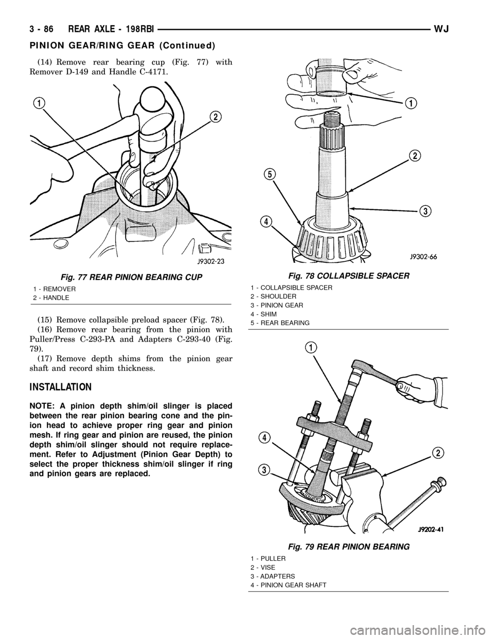
(14) Remove rear bearing cup (Fig. 77) with
Remover D-149 and Handle C-4171.
(15) Remove collapsible preload spacer (Fig. 78).
(16) Remove rear bearing from the pinion with
Puller/Press C-293-PA and Adapters C-293-40 (Fig.
79).
(17) Remove depth shims from the pinion gear
shaft and record shim thickness.
INSTALLATION
NOTE: A pinion depth shim/oil slinger is placed
between the rear pinion bearing cone and the pin-
ion head to achieve proper ring gear and pinion
mesh. If ring gear and pinion are reused, the pinion
depth shim/oil slinger should not require replace-
ment. Refer to Adjustment (Pinion Gear Depth) to
select the proper thickness shim/oil slinger if ring
and pinion gears are replaced.
Fig. 77 REAR PINION BEARING CUP
1 - REMOVER
2 - HANDLE
Fig. 78 COLLAPSIBLE SPACER
1 - COLLAPSIBLE SPACER
2 - SHOULDER
3 - PINION GEAR
4 - SHIM
5 - REAR BEARING
Fig. 79 REAR PINION BEARING
1 - PULLER
2 - VISE
3 - ADAPTERS
4 - PINION GEAR SHAFT
3 - 86 REAR AXLE - 198RBIWJ
PINION GEAR/RING GEAR (Continued)
Page 133 of 2199
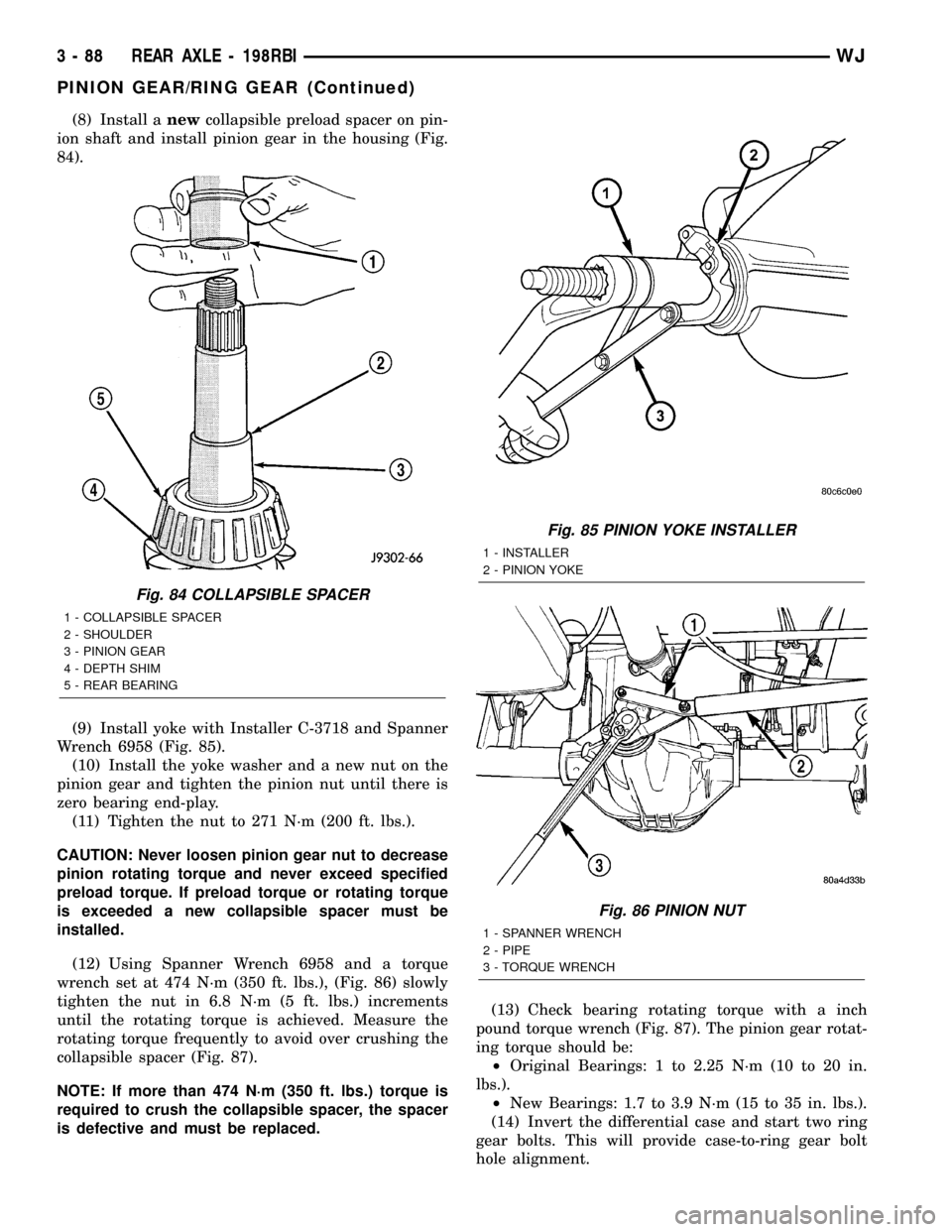
(8) Install anewcollapsible preload spacer on pin-
ion shaft and install pinion gear in the housing (Fig.
84).
(9) Install yoke with Installer C-3718 and Spanner
Wrench 6958 (Fig. 85).
(10) Install the yoke washer and a new nut on the
pinion gear and tighten the pinion nut until there is
zero bearing end-play.
(11) Tighten the nut to 271 N´m (200 ft. lbs.).
CAUTION: Never loosen pinion gear nut to decrease
pinion rotating torque and never exceed specified
preload torque. If preload torque or rotating torque
is exceeded a new collapsible spacer must be
installed.
(12) Using Spanner Wrench 6958 and a torque
wrench set at 474 N´m (350 ft. lbs.), (Fig. 86) slowly
tighten the nut in 6.8 N´m (5 ft. lbs.) increments
until the rotating torque is achieved. Measure the
rotating torque frequently to avoid over crushing the
collapsible spacer (Fig. 87).
NOTE: If more than 474 N´m (350 ft. lbs.) torque is
required to crush the collapsible spacer, the spacer
is defective and must be replaced.(13) Check bearing rotating torque with a inch
pound torque wrench (Fig. 87). The pinion gear rotat-
ing torque should be:
²Original Bearings: 1 to 2.25 N´m (10 to 20 in.
lbs.).
²New Bearings: 1.7 to 3.9 N´m (15 to 35 in. lbs.).
(14) Invert the differential case and start two ring
gear bolts. This will provide case-to-ring gear bolt
hole alignment.
Fig. 84 COLLAPSIBLE SPACER
1 - COLLAPSIBLE SPACER
2 - SHOULDER
3 - PINION GEAR
4 - DEPTH SHIM
5 - REAR BEARING
Fig. 85 PINION YOKE INSTALLER
1 - INSTALLER
2 - PINION YOKE
Fig. 86 PINION NUT
1 - SPANNER WRENCH
2 - PIPE
3 - TORQUE WRENCH
3 - 88 REAR AXLE - 198RBIWJ
PINION GEAR/RING GEAR (Continued)