window switch JEEP GRAND CHEROKEE 2002 WJ / 2.G Service Manual
[x] Cancel search | Manufacturer: JEEP, Model Year: 2002, Model line: GRAND CHEROKEE, Model: JEEP GRAND CHEROKEE 2002 WJ / 2.GPages: 2199, PDF Size: 76.01 MB
Page 1145 of 2199
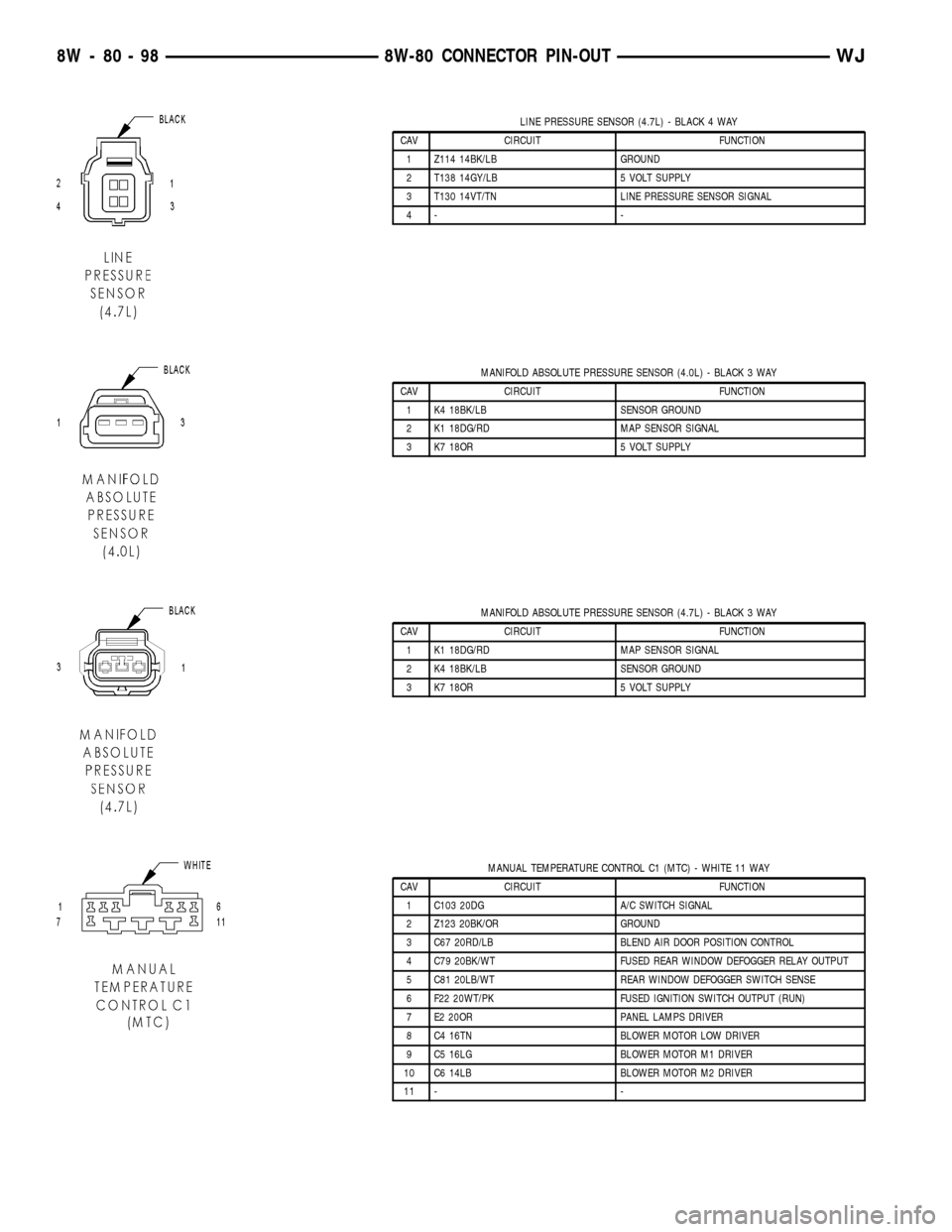
LINE PRESSURE SENSOR (4.7L) - BLACK 4 WAY
CAV CIRCUIT FUNCTION
1 Z114 14BK/LB GROUND
2 T138 14GY/LB 5 VOLT SUPPLY
3 T130 14VT/TN LINE PRESSURE SENSOR SIGNAL
4- -
MANIFOLD ABSOLUTE PRESSURE SENSOR (4.0L) - BLACK 3 WAY
CAV CIRCUIT FUNCTION
1 K4 18BK/LB SENSOR GROUND
2 K1 18DG/RD MAP SENSOR SIGNAL
3 K7 18OR 5 VOLT SUPPLY
MANIFOLD ABSOLUTE PRESSURE SENSOR (4.7L) - BLACK 3 WAY
CAV CIRCUIT FUNCTION
1 K1 18DG/RD MAP SENSOR SIGNAL
2 K4 18BK/LB SENSOR GROUND
3 K7 18OR 5 VOLT SUPPLY
MANUAL TEMPERATURE CONTROL C1 (MTC) - WHITE 11 WAY
CAV CIRCUIT FUNCTION
1 C103 20DG A/C SWITCH SIGNAL
2 Z123 20BK/OR GROUND
3 C67 20RD/LB BLEND AIR DOOR POSITION CONTROL
4 C79 20BK/WT FUSED REAR WINDOW DEFOGGER RELAY OUTPUT
5 C81 20LB/WT REAR WINDOW DEFOGGER SWITCH SENSE
6 F22 20WT/PK FUSED IGNITION SWITCH OUTPUT (RUN)
7 E2 20OR PANEL LAMPS DRIVER
8 C4 16TN BLOWER MOTOR LOW DRIVER
9 C5 16LG BLOWER MOTOR M1 DRIVER
10 C6 14LB BLOWER MOTOR M2 DRIVER
11 - -
8W - 80 - 98 8W-80 CONNECTOR PIN-OUTWJ
Page 1149 of 2199
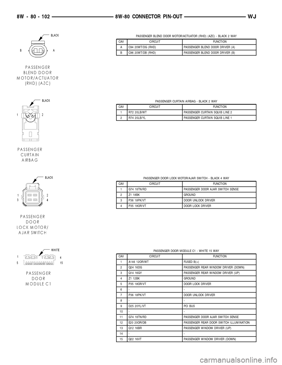
PASSENGER BLEND DOOR MOTOR/ACTUATOR (RHD) (AZC) - BLACK 2 WAY
CAV CIRCUIT FUNCTION
A C94 20WT/DG (RHD) PASSENGER BLEND DOOR DRIVER (A)
B C96 20WT/DB (RHD) PASSENGER BLEND DOOR DRIVER (B)
PASSENGER CURTAIN AIRBAG - BLACK 2 WAY
CAV CIRCUIT FUNCTION
1 R72 20LB/WT PASSENGER CURTAIN SQUIB LINE 2
2 R74 20LB/YL PASSENGER CURTAIN SQUIB LINE 1
PASSENGER DOOR LOCK MOTOR/AJAR SWITCH - BLACK 4 WAY
CAV CIRCUIT FUNCTION
1 G74 18TN/RD PASSENGER DOOR AJAR SWITCH SENSE
2 Z1 18BK GROUND
3 P36 18PK/VT DOOR UNLOCK DRIVER
4 P35 18OR/VT DOOR LOCK DRIVER
PASSENGER DOOR MODULE C1 - WHITE 15 WAY
CAV CIRCUIT FUNCTION
1 A146 12OR/WT FUSED B(+)
2 Q24 16DG PASSENGER REAR WINDOW DRIVER (DOWN)
3 Q14 16GY PASSENGER REAR WINDOW DRIVER (UP)
4 Z1 12BK GROUND
5 P35 18OR/VT DOOR LOCK DRIVER
6- -
7 P36 18PK/VT DOOR UNLOCK DRIVER
8- -
9 D25 20YL/VT PCI BUS
10 - -
11 G74 18TN/RD PASSENGER DOOR AJAR SWITCH SENSE
12 E20 20OR/DB PASSENGER REAR DOOR SWITCH ILLUMINATION
13 Q12 16BR PASSENGER WINDOW DRIVER (UP)
14 - -
15 Q22 16VT PASSENGER WINDOW DRIVER (DOWN)
8W - 80 - 102 8W-80 CONNECTOR PIN-OUTWJ
Page 1153 of 2199
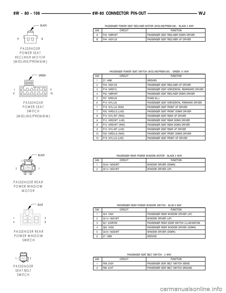
PASSENGER POWER SEAT RECLINER MOTOR (MIDLINE/PREMIUM) - BLACK 2 WAY
CAV CIRCUIT FUNCTION
A P42 16BR/WT PASSENGER SEAT RECLINER DOWN DRIVER
B P44 16GY/LB PASSENGER SEAT RECLINER UP DRIVER
PASSENGER POWER SEAT SWITCH (MIDLINE/PREMIUM) - GREEN 10 WAY
CAV CIRCUIT FUNCTION
1 Z1 16BK GROUND
2 P44 16GY/LB PASSENGER SEAT RECLINER UP DRIVER
3 P16 16RD/YL PASSENGER SEAT HORIZONTAL REARWARD DRIVER
4 P42 16BR/WT PASSENGER SEAT RECLINER DOWN DRIVER
5 F37 16RD/LB FUSED B(+)
6 P14 16YL/LB PASSENGER SEAT HORIZONTAL FORWARD DRIVER
7 P18 16YL/LG (RHD) PASSENGER SEAT FRONT UP DRIVER
7 P20 16RD/LG (LHD) PASSENGER SEAT FRONT DOWN DRIVER
8 P10 16YL/WT (RHD) PASSENGER SEAT REAR UP DRIVER
8 P12 16RD/WT (LHD) PASSENGER SEAT REAR DOWN DRIVER
9 P12 16RD/WT (RHD) PASSENGER SEAT REAR DOWN DRIVER
9 P10 16YL/WT (LHD) PASSENGER SEAT REAR UP DRIVER
10 P20 16RD/LG (RHD) PASSENGER SEAT FRONT DOWN DRIVER
10 P18 16YL/LG (LHD) PASSENGER SEAT FRONT UP DRIVER
PASSENGER REAR POWER WINDOW MOTOR - BLACK 2 WAY
CAV CIRCUIT FUNCTION
1 Q124 16DG/WT WINDOW DRIVER (DOWN)
2 Q114 16GY/WT WINDOW DRIVER (UP)
PASSENGER REAR POWER WINDOW SWITCH - BLUE 6 WAY
CAV CIRCUIT FUNCTION
1 Q14 16GY PASSENGER REAR WINDOW DRIVER (UP)
2 Q114 16GY/WT WINDOW DRIVER (UP)
3 E21 20OR/RD PASSENGER REAR DOOR SWITCH ILLUMINATION
4 Q24 16DG PASSENGER REAR WINDOW DRIVER (DOWN)
5 Q124 16DG/WT WINDOW DRIVER (DOWN)
6 Z1 16BK GROUND
PASSENGER SEAT BELT SWITCH-2WAY
CAV CIRCUIT FUNCTION
1 R58 20GY PASSENGER SEAT BELT SWITCH SENSE
2 R60 20VT PASSENGER SEAT BELT SWITCH GROUND
8W - 80 - 106 8W-80 CONNECTOR PIN-OUTWJ
Page 1176 of 2199
8W-91 CONNECTOR/GROUND/SPLICE LOCATION
TABLE OF CONTENTS
page
CONNECTOR/GROUND/SPLICE LOCATION
DESCRIPTION..........................1
CONNECTOR/GROUND/SPLICE
LOCATION
DESCRIPTION
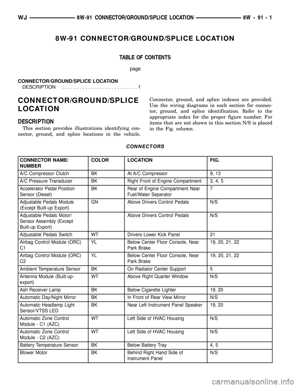
This section provides illustrations identifying con-
nector, ground, and splice locations in the vehicle.Connector, ground, and splice indexes are provided.
Use the wiring diagrams in each section for connec-
tor, ground, and splice identification. Refer to the
appropriate index for the proper figure number. For
items that are not shown in this section N/S is placed
in the Fig. column.
CONNECTORS
CONNECTOR NAME/
NUMBERCOLOR LOCATION FIG.
A/C Compressor Clutch BK At A/C Compressor 9, 13
A/C Pressure Transducer BK Right Front of Engine Compartment 3, 4, 5
Accelerator Pedal Position
Sensor (Diesel)BK Rear of Engine Compartment Near
Fuel/Water Seperator7
Adjustable Pedals Module
(Except Built-up Export)GN Above Drivers Control Pedals N/S
Adjustable Pedals Motor/
Sensor Assembly (Except
Built-up Export)Above Drivers Control Pedals N/S
Adjustable Pedals Switch WT Drivers Lower Kick Panel 21
Airbag Control Module (ORC)
C1YL Below Center Floor Console, Near
Park Brake19, 20, 21, 22
Airbag Control Module (ORC)
C2YL Below Center Floor Console, Near
Park Brake19, 20, 21, 22
Ambient Temperature Sensor BK On Radiator Center Support 5
Antenna Module (Built-up-
export)WT Above Right Quarter Window N/S
Ash Receiver Lamp BK Below Cigarette Lighter 19, 20
Automatic Day/Night Mirror BK In Front of Rear View Mirror N/S
Automatic Headlamp Light
Sensor/VTSS LEDBK Near Left Instrument Panel Speaker 19, 20
Automatic Zone Control
Module - C1 (AZC)WT Left Side of HVAC Housing N/S
Automatic Zone Control
Module - C2 (AZC)WT Left Side of HVAC Housing N/S
Battery Temperature Sensor BK Below Battery Tray 4, 5
Blower Motor BK Behind Right Hand Side of
Instrument PanelN/S
WJ8W-91 CONNECTOR/GROUND/SPLICE LOCATION 8W - 91 - 1
Page 1179 of 2199
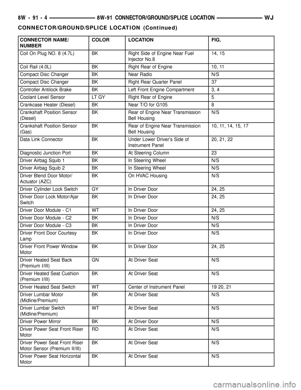
CONNECTOR NAME/
NUMBERCOLOR LOCATION FIG.
Coil On Plug NO. 8 (4.7L) BK Right Side of Engine Near Fuel
Injector No.814, 15
Coil Rail (4.0L) BK Right Rear of Engine 10, 11
Compact Disc Changer BK Near Radio N/S
Compact Disc Changer BK Right Rear Quarter Panel 37
Controller Antilock Brake BK Left Front Engine Compartment 3, 4
Coolant Level Sensor LT GY Right Rear of Engine 5
Crankcase Heater (Diesel) BK Near T/O for G105 8
Crankshaft Position Sensor
(Diesel)BK Rear of Engine Near Transmission
Bell HousingN/S
Crankshaft Position Sensor
(Gas)BK Rear of Engine Near Transmission
Bell Housing10, 11, 14, 15, 17
Data Link Connector BK Under Lower Driver's Side of
Instrument Panel20, 21, 22
Diagnostic Junction Port BK At Steering Column 23
Driver Airbag Squib 1 BK In Steering Wheel N/S
Driver Airbag Squib 2 BK In Steering Wheel N/S
Driver Blend Door Motor/
Actuator (AZC)BK On HVAC Housing N/S
Driver Cylinder Lock Switch GY In Driver Door 24, 25
Driver Door Lock Motor/Ajar
SwitchBK In Driver Door 24, 25
Driver Door Module - C1 WT In Driver Door 24, 25
Driver Door Module - C2 BK In Driver Door N/S
Driver Door Module - C3 BK In Driver Door N/S
Driver Front Door Courtesy
LampBK In Driver Door N/S
Driver Front Power Window
MotorBK In Driver Door 24, 25
Driver Heated Seat Back
(Premium I/III)GN At Driver Seat N/S
Driver Heated Seat Cushion
(Premium I/III)BK At Driver Seat N/S
Driver Heated Seat Switch WT Center of Instrument Panel 19 20, 21
Driver Lumbar Motor
(Midline/Premium)BK At Driver Seat N/S
Driver Lumbar Switch
(Midline/Premium)WT At Driver Seat N/S
Driver Power Mirror BK At Driver Door N/S
Driver Power Seat Front Riser
MotorRD At Driver Seat N/S
Driver Power Seat Front Riser
Motor Sensor (Premium II/III)BK At Driver Seat N/S
Driver Power Seat Horizontal
MotorBK At Driver Seat N/S
8W - 91 - 4 8W-91 CONNECTOR/GROUND/SPLICE LOCATIONWJ
CONNECTOR/GROUND/SPLICE LOCATION (Continued)
Page 1180 of 2199
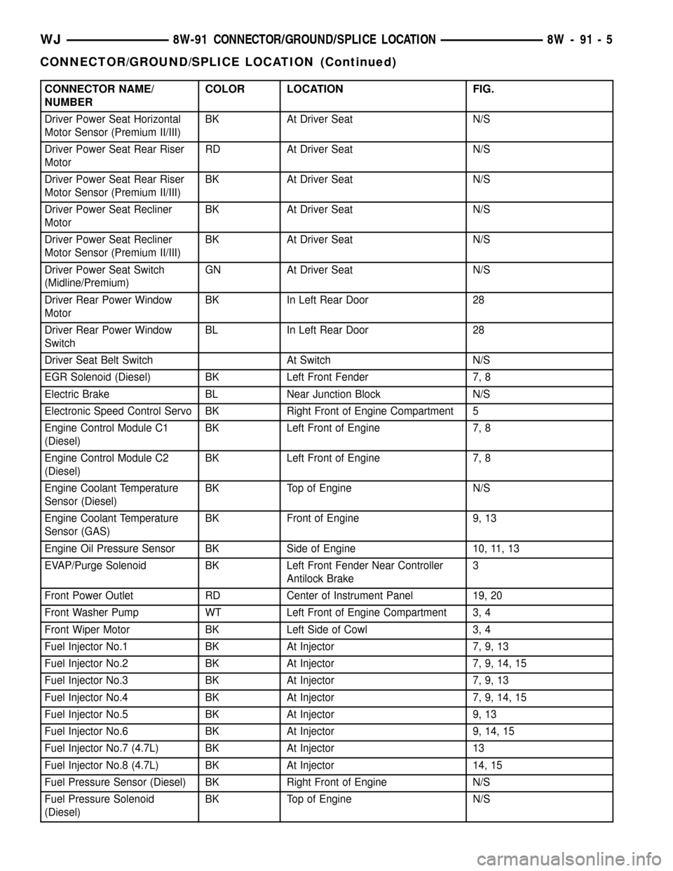
CONNECTOR NAME/
NUMBERCOLOR LOCATION FIG.
Driver Power Seat Horizontal
Motor Sensor (Premium II/III)BK At Driver Seat N/S
Driver Power Seat Rear Riser
MotorRD At Driver Seat N/S
Driver Power Seat Rear Riser
Motor Sensor (Premium II/III)BK At Driver Seat N/S
Driver Power Seat Recliner
MotorBK At Driver Seat N/S
Driver Power Seat Recliner
Motor Sensor (Premium II/III)BK At Driver Seat N/S
Driver Power Seat Switch
(Midline/Premium)GN At Driver Seat N/S
Driver Rear Power Window
MotorBK In Left Rear Door 28
Driver Rear Power Window
SwitchBL In Left Rear Door 28
Driver Seat Belt Switch At Switch N/S
EGR Solenoid (Diesel) BK Left Front Fender 7, 8
Electric Brake BL Near Junction Block N/S
Electronic Speed Control Servo BK Right Front of Engine Compartment 5
Engine Control Module C1
(Diesel)BK Left Front of Engine 7, 8
Engine Control Module C2
(Diesel)BK Left Front of Engine 7, 8
Engine Coolant Temperature
Sensor (Diesel)BK Top of Engine N/S
Engine Coolant Temperature
Sensor (GAS)BK Front of Engine 9, 13
Engine Oil Pressure Sensor BK Side of Engine 10, 11, 13
EVAP/Purge Solenoid BK Left Front Fender Near Controller
Antilock Brake3
Front Power Outlet RD Center of Instrument Panel 19, 20
Front Washer Pump WT Left Front of Engine Compartment 3, 4
Front Wiper Motor BK Left Side of Cowl 3, 4
Fuel Injector No.1 BK At Injector 7, 9, 13
Fuel Injector No.2 BK At Injector 7, 9, 14, 15
Fuel Injector No.3 BK At Injector 7, 9, 13
Fuel Injector No.4 BK At Injector 7, 9, 14, 15
Fuel Injector No.5 BK At Injector 9, 13
Fuel Injector No.6 BK At Injector 9, 14, 15
Fuel Injector No.7 (4.7L) BK At Injector 13
Fuel Injector No.8 (4.7L) BK At Injector 14, 15
Fuel Pressure Sensor (Diesel) BK Right Front of Engine N/S
Fuel Pressure Solenoid
(Diesel)BK Top of Engine N/S
WJ8W-91 CONNECTOR/GROUND/SPLICE LOCATION 8W - 91 - 5
CONNECTOR/GROUND/SPLICE LOCATION (Continued)
Page 1183 of 2199
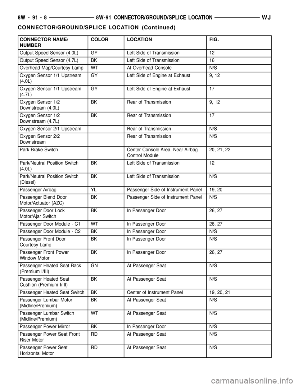
CONNECTOR NAME/
NUMBERCOLOR LOCATION FIG.
Output Speed Sensor (4.0L) GY Left Side of Transmission 12
Output Speed Sensor (4.7L) BK Left Side of Transmission 16
Overhead Map/Courtesy Lamp WT At Overhead Console N/S
Oxygen Sensor 1/1 Upstream
(4.0L)GY Left Side of Engine at Exhaust 9, 12
Oxygen Sensor 1/1 Upstream
(4.7L)GY Left Side of Engine at Exhaust 17
Oxygen Sensor 1/2
Downstream (4.0L)BK Rear of Transmission 9, 12
Oxygen Sensor 1/2
Downstream (4.7L)BK Rear of Transmission 17
Oxygen Sensor 2/1 Upstream Rear of Transmission N/S
Oxygen Sensor 2/2
DownstreamRear of Transmission N/S
Park Brake Switch Center Console Area, Near Airbag
Control Module20, 21, 22
Park/Neutral Position Switch
(4.0L)BK Left Side of Transmission 12
Park/Neutral Position Switch
(Diesel)BK Left Side of Transmission N/S
Passenger Airbag YL Passenger Side of Instrument Panel 19, 20
Passenger Blend Door
Motor/Actuator (AZC)BK Passenger Side of Instrument Panel N/S
Passenger Door Lock
Motor/Ajar SwitchBK In Passenger Door 26, 27
Passenger Door Module - C1 WT In Passenger Door 26, 27
Passenger Door Module - C2 BK In Passenger Door N/S
Passenger Front Door
Courtesy LampBK In Passenger Door N/S
Passenger Front Power
Window MotorBK In Passenger Door 26, 27
Passenger Heated Seat Back
(Premium I/III)GN At Passenger Seat N/S
Passenger Heated Seat
Cushion (Premium I/III)BK At Passenger Seat N/S
Passenger Heated Seat Switch BK Center of Instrument Panel 19, 20, 21
Passenger Lumbar Motor
(Midline/Premium)BK At Passenger Seat N/S
Passenger Lumbar Switch
(Midline/Premium)WT At Passenger Seat N/S
Passenger Power Mirror BK In Passenger Door N/S
Passenger Power Seat Front
Riser MotorRD At Passenger Seat N/S
Passenger Power Seat
Horizontal MotorRD At Passenger Seat N/S
8W - 91 - 8 8W-91 CONNECTOR/GROUND/SPLICE LOCATIONWJ
CONNECTOR/GROUND/SPLICE LOCATION (Continued)
Page 1184 of 2199
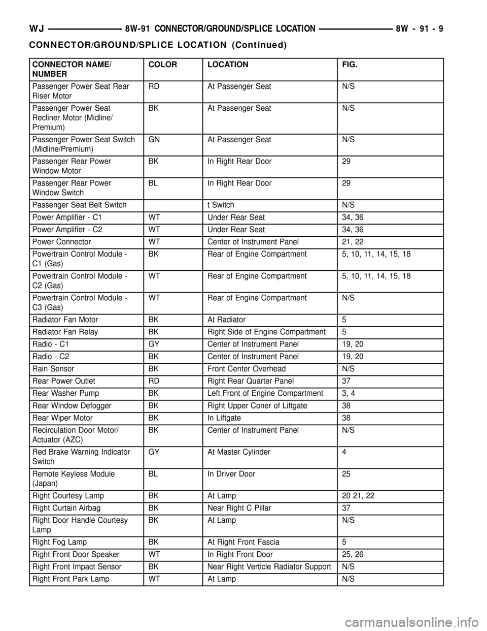
CONNECTOR NAME/
NUMBERCOLOR LOCATION FIG.
Passenger Power Seat Rear
Riser MotorRD At Passenger Seat N/S
Passenger Power Seat
Recliner Motor (Midline/
Premium)BK At Passenger Seat N/S
Passenger Power Seat Switch
(Midline/Premium)GN At Passenger Seat N/S
Passenger Rear Power
Window MotorBK In Right Rear Door 29
Passenger Rear Power
Window SwitchBL In Right Rear Door 29
Passenger Seat Belt Switch t Switch N/S
Power Amplifier - C1 WT Under Rear Seat 34, 36
Power Amplifier - C2 WT Under Rear Seat 34, 36
Power Connector WT Center of Instrument Panel 21, 22
Powertrain Control Module -
C1 (Gas)BK Rear of Engine Compartment 5, 10, 11, 14, 15, 18
Powertrain Control Module -
C2 (Gas)WT Rear of Engine Compartment 5, 10, 11, 14, 15, 18
Powertrain Control Module -
C3 (Gas)WT Rear of Engine Compartment N/S
Radiator Fan Motor BK At Radiator 5
Radiator Fan Relay BK Right Side of Engine Compartment 5
Radio - C1 GY Center of Instrument Panel 19, 20
Radio - C2 BK Center of Instrument Panel 19, 20
Rain Sensor BK Front Center Overhead N/S
Rear Power Outlet RD Right Rear Quarter Panel 37
Rear Washer Pump BK Left Front of Engine Compartment 3, 4
Rear Window Defogger BK Right Upper Coner of Liftgate 38
Rear Wiper Motor BK In Liftgate 38
Recirculation Door Motor/
Actuator (AZC)BK Center of Instrument Panel N/S
Red Brake Warning Indicator
SwitchGY At Master Cylinder 4
Remote Keyless Module
(Japan)BL In Driver Door 25
Right Courtesy Lamp BK At Lamp 20 21, 22
Right Curtain Airbag BK Near Right C Pillar 37
Right Door Handle Courtesy
LampBK At Lamp N/S
Right Fog Lamp BK At Right Front Fascia 5
Right Front Door Speaker WT In Right Front Door 25, 26
Right Front Impact Sensor BK Near Right Verticle Radiator Support N/S
Right Front Park Lamp WT At Lamp N/S
WJ8W-91 CONNECTOR/GROUND/SPLICE LOCATION 8W - 91 - 9
CONNECTOR/GROUND/SPLICE LOCATION (Continued)
Page 1191 of 2199
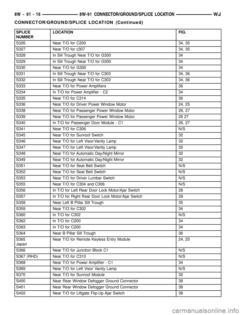
SPLICE
NUMBERLOCATION FIG.
S326 Near T/O for C200 34, 35
S327 Near T/O for c307 34, 35
S328 In Sill Trough Near T/O for G300 34
S329 In Sill Trough Near T/O for G300 34
S330 Near T/O for G300 34
S331 In Sill Trough Near T/O for C303 34, 36
S332 In Sill Trough Near T/O for C303 34, 36
S333 Near T/O for Power Amplifiers 36
S334 In T/O for Power Amplifier - C2 34
S335 Near T/O for C314 36
S336 Near T/O for Driver Power Window Motor 24, 25
S338 Near T/O for Passenger Power Window Motor 26, 27
S339 Near T/O for Passenger Power Window Motor 26 27
S340 In T/O for Passenger Door Module - C1 26, 27
S341 Near T/O for C306 N/S
S345 Near T/O for Sunroof Switch 32
S346 Near T/O for Left Visor/Vanity Lamp 32
S347 Near T/O for Left Visor/Vanity Lamp 32
S348 Near T/O for Automatic Day/Night Mirror 32
S349 Near T/O for Automatic Day/Night Mirror 32
S351 Near T/O for Seat Belt Switch N/S
S352 Near T/O for Seat Belt Switch N/S
S353 Near T/O for Driver Lumbar Switch N/S
S355 Near T/O for C304 and C306 N/S
S356 In T/O for Left Rear Door Lock Motor/Ajar Switch 28
S357 In T/O for Right Rear Door Lock Motor/Ajar Switch 29
S358 Near Left B Pillar Sill Trough 35
S359 Near T/O for C302 34
S360 In T/O for C302 N/S
S362 In T/O for C200 34
S363 In T/O for C200 34
S364 Near B Pillar Sill Trough 36
S365
JapanNear T/O for Remote Keyless Entry Module 24, 25
S366 Near T/O for Junction Block C1 N/S
S367 (RHD) Near T/O for C310 N/S
S368 Near T/O for Power Amplifier - C1 34
S369 Near T/O for Left Visor Vanity Lamp N/S
S370 Near T/O for Sunroof Module 32
S400 Near Rear Window Defogger Ground Connector 38
S401 Near Rear Window Defogger Ground Connector 38
S402 Near T/O for Liftgate Flip-Up Ajar Switch 38
8W - 91 - 16 8W-91 CONNECTOR/GROUND/SPLICE LOCATIONWJ
CONNECTOR/GROUND/SPLICE LOCATION (Continued)
Page 1974 of 2199

CONTROL MODULE
REMOVAL
(1) Move the glass panel to the fully closed posi-
tion.
(2) Remove the A-pillar trim. (Refer to 23 - BODY/
INTERIOR/A-PILLAR TRIM - REMOVAL)
(3) Remove the sun visors. (Refer to 23 - BODY/
INTERIOR/SUN VISOR - REMOVAL)
(4) Remove the overhead console. (Refer to 8 -
ELECTRICAL/OVERHEAD CONSOLE - REMOVAL)
(5) Lower headliner as necessary to gain access to
the sunroof express module.
(6) Disconnect the express module wire harness
connectors.
(7) Remove express module screw.
(8) Remove express module from the keyway by
sliding module towards the center of the vehicle.
INSTALLATION
(1) Insert sunroof express module in the keyway
located in the sunroof module and slide the module
outward to lock it into position.
(2) Install the sunroof express module screw.
(3) Connect the wire connectors to the sunroof
express module.
(4) Install the headliner into position.
(5) Install the overhead console. (Refer to 8 -
ELECTRICAL/OVERHEAD CONSOLE - INSTALLA-
TION)
(6) Install the sun visors. (Refer to 23 - BODY/IN-
TERIOR/SUN VISOR - INSTALLATION)
(7) Install the A-pillar trim. (Refer to 23 - BODY/
INTERIOR/A-PILLAR TRIM - INSTALLATION)
(8) Test sunroof operation, adjust if necessary.
(Refer to 23 - BODY/SUNROOF/GLASS PANEL -
ADJUSTMENTS)
DRIVE MOTOR
REMOVAL
CAUTION: The sunroof system is timed from the
factory so that the motor shuts off automatically
when the sunroof window reaches a certain posi-
tion. Extreme care must be taken when removing
the motor, timing may be thrown off causing possi-
ble damage to the sunroof system. Anytime the
motor is removed from the sunroof assembly the
sunroof glass panel must be in the FULLY CLOSED
POSITION or the unit will be out of timing. The drive
motor cannot be reset to the park position after
being removed.CAUTION: The sunroof motor should only be pow-
ered through the vehicle battery and sunroof wire
harness. Applying power to the sunroof motor leads
will cause failure of the control module.
(1) Move glass panel to the fully closed position.
(2) Remove the A-pillar trim. (Refer to 23 - BODY/
INTERIOR/A-PILLAR TRIM - REMOVAL)
(3) Remove the B-pillar upper trim. (Refer to 23 -
BODY/INTERIOR/B-PILLAR UPPER TRIM -
REMOVAL)
(4) Remove the C-pillar trim. (Refer to 23 - BODY/
INTERIOR/C-PILLAR TRIM - REMOVAL)
(5) Remove the D-pillar trim. (Refer to 23 - BODY/
INTERIOR/D-PILLAR TRIM - REMOVAL)
(6) Remove the sunvisors. (Refer to 23 - BODY/IN-
TERIOR/SUN VISOR - REMOVAL)
(7) Remove the overhead console. (Refer to 8 -
ELECTRICAL/OVERHEAD CONSOLE - REMOVAL)
(8) Disconnect the control switch wire connector.
(9) Remove headliner as necessary to gain access
to sunroof drive motor. Refer to Headliner Removal
and Installation for proper procedures.
(10) Disconnect the drive motor wire harness con-
nectors (Fig. 3).
(11) Remove drive motor fasteners and remove
motor from the sunroof housing.
INSTALLATION
(1) Ensure that the window is in the fully closed
position before mounting the motor. If motor fails
with the window in the open position the sunroof
glass panel timing will have to be timed. The new
motor comes in the fully closed position and with a
gage for setting cable timing. (Refer to 23 - BODY/
SUNROOF/GLASS PANEL - ADJUSTMENTS - TIM-
ING)
(2) Place drive motor into position on the sunroof
housing and install fasteners.
Fig. 3 Sunroof Drive Motor and Express Module
1 - EXPRESS MODULE
2 - SCREW
WJSUNROOF 23 - 101