4.7l v8 ac system JEEP GRAND CHEROKEE 2002 WJ / 2.G Repair Manual
[x] Cancel search | Manufacturer: JEEP, Model Year: 2002, Model line: GRAND CHEROKEE, Model: JEEP GRAND CHEROKEE 2002 WJ / 2.GPages: 2199, PDF Size: 76.01 MB
Page 1343 of 2199
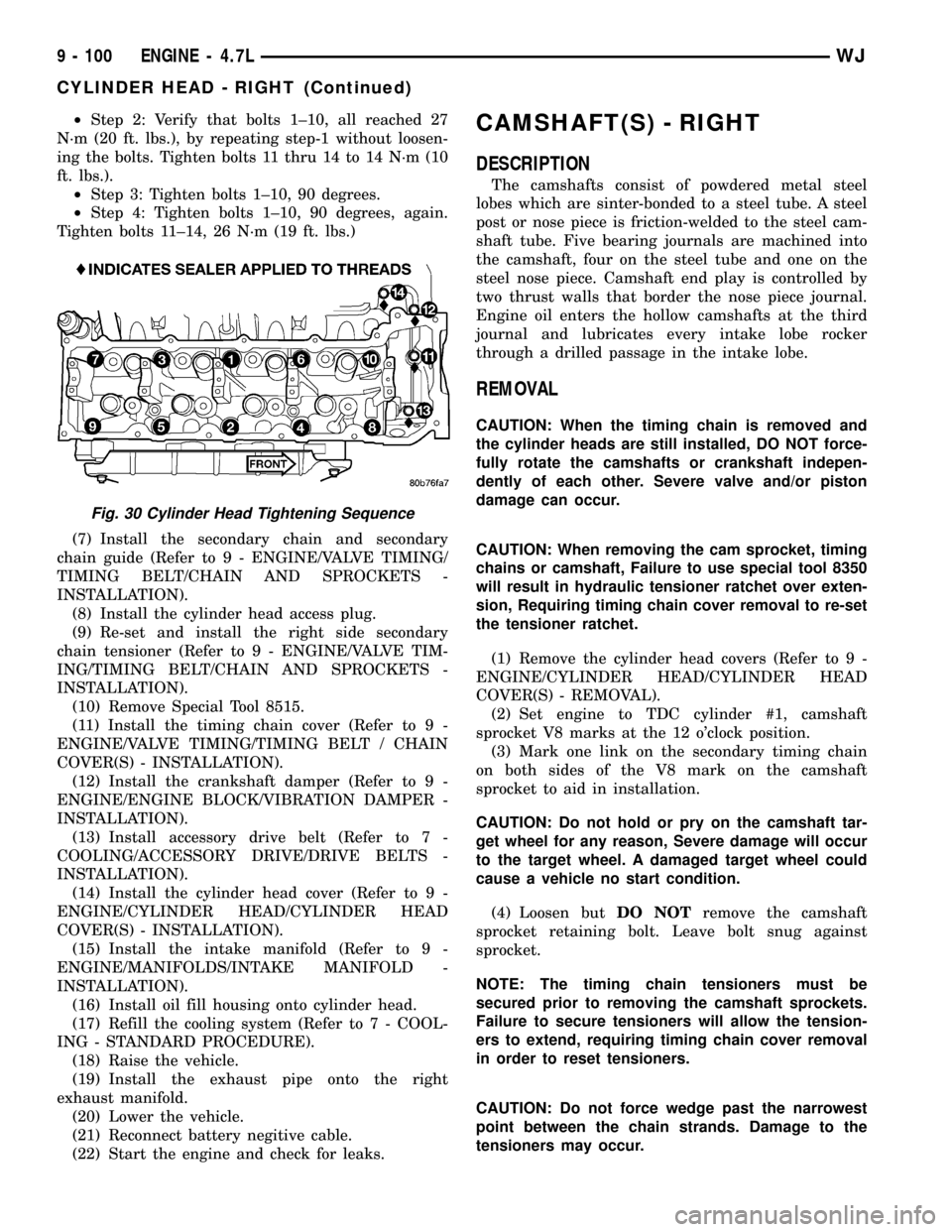
²Step 2: Verify that bolts 1±10, all reached 27
N´m (20 ft. lbs.), by repeating step-1 without loosen-
ing the bolts. Tighten bolts 11 thru 14 to 14 N´m (10
ft. lbs.).
²Step 3: Tighten bolts 1±10, 90 degrees.
²Step 4: Tighten bolts 1±10, 90 degrees, again.
Tighten bolts 11±14, 26 N´m (19 ft. lbs.)
(7) Install the secondary chain and secondary
chain guide (Refer to 9 - ENGINE/VALVE TIMING/
TIMING BELT/CHAIN AND SPROCKETS -
INSTALLATION).
(8) Install the cylinder head access plug.
(9) Re-set and install the right side secondary
chain tensioner (Refer to 9 - ENGINE/VALVE TIM-
ING/TIMING BELT/CHAIN AND SPROCKETS -
INSTALLATION).
(10) Remove Special Tool 8515.
(11) Install the timing chain cover (Refer to 9 -
ENGINE/VALVE TIMING/TIMING BELT / CHAIN
COVER(S) - INSTALLATION).
(12) Install the crankshaft damper (Refer to 9 -
ENGINE/ENGINE BLOCK/VIBRATION DAMPER -
INSTALLATION).
(13) Install accessory drive belt (Refer to 7 -
COOLING/ACCESSORY DRIVE/DRIVE BELTS -
INSTALLATION).
(14) Install the cylinder head cover (Refer to 9 -
ENGINE/CYLINDER HEAD/CYLINDER HEAD
COVER(S) - INSTALLATION).
(15) Install the intake manifold (Refer to 9 -
ENGINE/MANIFOLDS/INTAKE MANIFOLD -
INSTALLATION).
(16) Install oil fill housing onto cylinder head.
(17) Refill the cooling system (Refer to 7 - COOL-
ING - STANDARD PROCEDURE).
(18) Raise the vehicle.
(19) Install the exhaust pipe onto the right
exhaust manifold.
(20) Lower the vehicle.
(21) Reconnect battery negitive cable.
(22) Start the engine and check for leaks.CAMSHAFT(S) - RIGHT
DESCRIPTION
The camshafts consist of powdered metal steel
lobes which are sinter-bonded to a steel tube. A steel
post or nose piece is friction-welded to the steel cam-
shaft tube. Five bearing journals are machined into
the camshaft, four on the steel tube and one on the
steel nose piece. Camshaft end play is controlled by
two thrust walls that border the nose piece journal.
Engine oil enters the hollow camshafts at the third
journal and lubricates every intake lobe rocker
through a drilled passage in the intake lobe.
REMOVAL
CAUTION: When the timing chain is removed and
the cylinder heads are still installed, DO NOT force-
fully rotate the camshafts or crankshaft indepen-
dently of each other. Severe valve and/or piston
damage can occur.
CAUTION: When removing the cam sprocket, timing
chains or camshaft, Failure to use special tool 8350
will result in hydraulic tensioner ratchet over exten-
sion, Requiring timing chain cover removal to re-set
the tensioner ratchet.
(1) Remove the cylinder head covers (Refer to 9 -
ENGINE/CYLINDER HEAD/CYLINDER HEAD
COVER(S) - REMOVAL).
(2) Set engine to TDC cylinder #1, camshaft
sprocket V8 marks at the 12 o'clock position.
(3) Mark one link on the secondary timing chain
on both sides of the V8 mark on the camshaft
sprocket to aid in installation.
CAUTION: Do not hold or pry on the camshaft tar-
get wheel for any reason, Severe damage will occur
to the target wheel. A damaged target wheel could
cause a vehicle no start condition.
(4) Loosen butDO NOTremove the camshaft
sprocket retaining bolt. Leave bolt snug against
sprocket.
NOTE: The timing chain tensioners must be
secured prior to removing the camshaft sprockets.
Failure to secure tensioners will allow the tension-
ers to extend, requiring timing chain cover removal
in order to reset tensioners.
CAUTION: Do not force wedge past the narrowest
point between the chain strands. Damage to the
tensioners may occur.
Fig. 30 Cylinder Head Tightening Sequence
9 - 100 ENGINE - 4.7LWJ
CYLINDER HEAD - RIGHT (Continued)
Page 1347 of 2199
CYLINDER HEAD COVER(S) -
RIGHT
DESCRIPTION
The cylinder head covers are made of die cast mag-
nesium, and are not interchangeable from side-to-
side. It is imperative that nothing rest on the
cylinder head covers. Prolonged contact with other
items may wear a hole in the cylinder head cover.
REMOVAL - RIGHT SIDE
(1) Disconnect battery negative cable.
(2) Remove air cleaner assembly, resonator assem-
bly and air inlet hose.
(3) Drain cooling system (Refer to 7 - COOLING -
STANDARD PROCEDURE).
(4) Remove accessory drive belt (Refer to 7 -
COOLING/ACCESSORY DRIVE/DRIVE BELTS -
REMOVAL).
(5) Remove air conditioning compressor retaining
bolts and move compressor to the left.
(6) Remove heater hoses.
(7) Disconnect injector and ignition coil connectors.
(8) Disconnect and remove positive crankcase ven-
tilation (PCV) hose.
(9) Remove oil fill tube.
(10) Un-clip injector and ignition coil harness and
move away from cylinder head cover.
(11) Remove right rear breather tube and filter
assembly.
(12) Remove cylinder head cover retaining bolts.
(13) Remove cylinder head cover.
NOTE: The gasket may be used again, provided no
cuts, tears, or deformation has occurred.
CLEANING
Clean cylinder head cover gasket surface.
Clean head rail, if necessary.
INSTALLATION - RIGHT SIDE
CAUTION: Do not use harsh cleaners to clean the
cylinder head covers. Severe damage to covers
may occur.
CAUTION: DO NOT allow other components includ-
ing the wire harness to rest on or against the
engine cylinder head cover. Prolonged contact with
other objects may wear a hole in the cylinder head
cover.
(1) Clean cylinder head cover and both sealing sur-
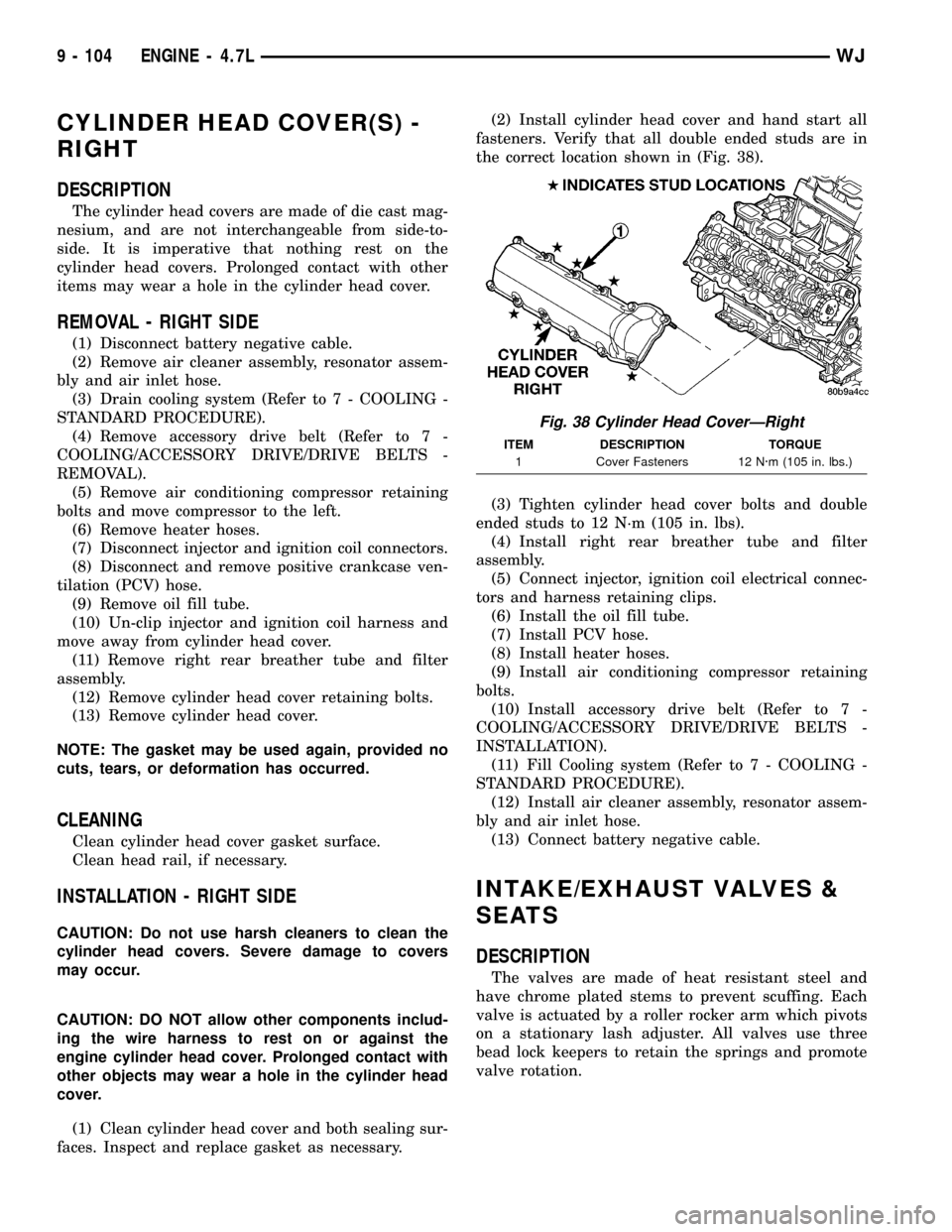
faces. Inspect and replace gasket as necessary.(2) Install cylinder head cover and hand start all
fasteners. Verify that all double ended studs are in
the correct location shown in (Fig. 38).
(3) Tighten cylinder head cover bolts and double
ended studs to 12 N´m (105 in. lbs).
(4) Install right rear breather tube and filter
assembly.
(5) Connect injector, ignition coil electrical connec-
tors and harness retaining clips.
(6) Install the oil fill tube.
(7) Install PCV hose.
(8) Install heater hoses.
(9) Install air conditioning compressor retaining
bolts.
(10) Install accessory drive belt (Refer to 7 -
COOLING/ACCESSORY DRIVE/DRIVE BELTS -
INSTALLATION).
(11) Fill Cooling system (Refer to 7 - COOLING -
STANDARD PROCEDURE).
(12) Install air cleaner assembly, resonator assem-
bly and air inlet hose.
(13) Connect battery negative cable.
INTAKE/EXHAUST VALVES &
SEATS
DESCRIPTION
The valves are made of heat resistant steel and
have chrome plated stems to prevent scuffing. Each
valve is actuated by a roller rocker arm which pivots
on a stationary lash adjuster. All valves use three
bead lock keepers to retain the springs and promote
valve rotation.
Fig. 38 Cylinder Head CoverÐRight
ITEM DESCRIPTION TORQUE
1 Cover Fasteners 12 N´m (105 in. lbs.)
9 - 104 ENGINE - 4.7LWJ
Page 1358 of 2199
CRANKSHAFT MAIN BEARING SELECTION
The main bearings are ªselect fitº to achieve proper
oil clearances. For main bearing selection, the crank-
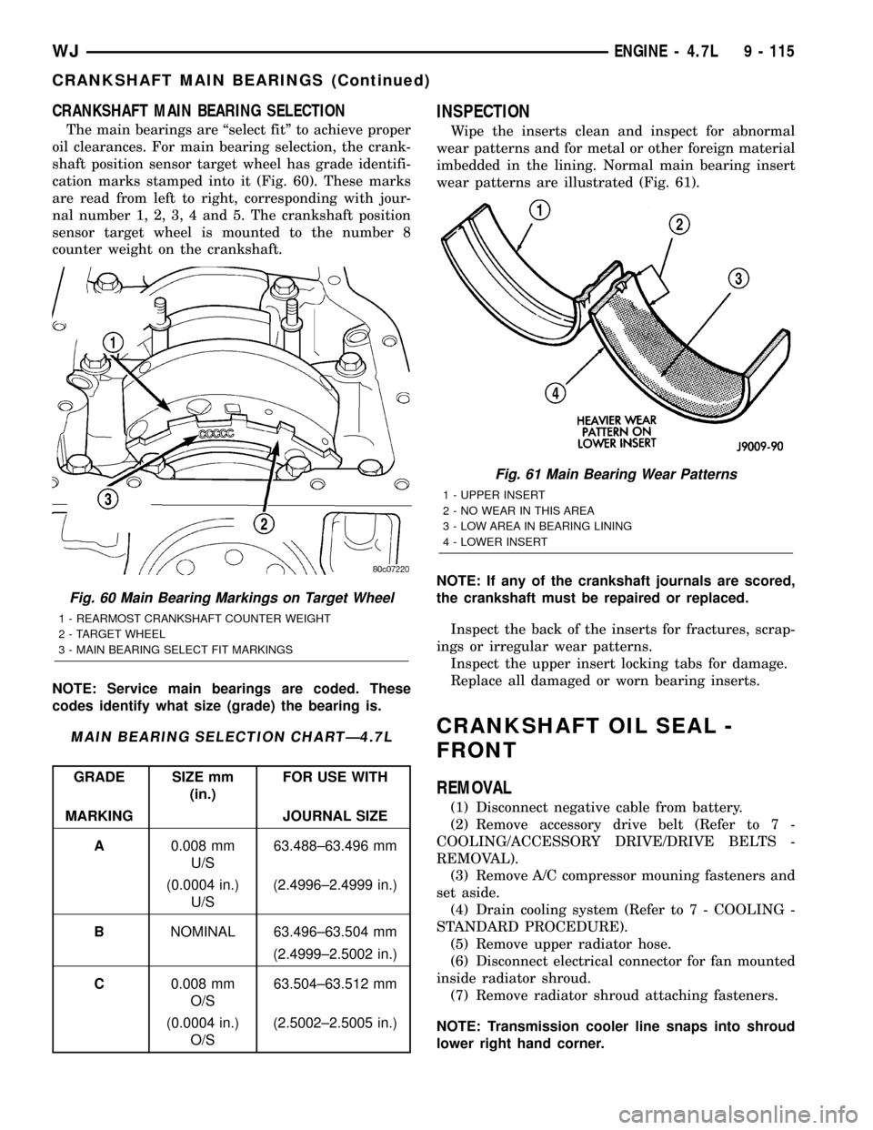
shaft position sensor target wheel has grade identifi-
cation marks stamped into it (Fig. 60). These marks
are read from left to right, corresponding with jour-
nal number 1, 2, 3, 4 and 5. The crankshaft position
sensor target wheel is mounted to the number 8
counter weight on the crankshaft.
NOTE: Service main bearings are coded. These
codes identify what size (grade) the bearing is.
MAIN BEARING SELECTION CHARTÐ4.7L
GRADE SIZE mm
(in.)FOR USE WITH
MARKING JOURNAL SIZE
A0.008 mm
U/S63.488±63.496 mm
(0.0004 in.)
U/S(2.4996±2.4999 in.)
BNOMINAL 63.496±63.504 mm
(2.4999±2.5002 in.)
C0.008 mm
O/S63.504±63.512 mm
(0.0004 in.)
O/S(2.5002±2.5005 in.)
INSPECTION
Wipe the inserts clean and inspect for abnormal
wear patterns and for metal or other foreign material
imbedded in the lining. Normal main bearing insert
wear patterns are illustrated (Fig. 61).
NOTE: If any of the crankshaft journals are scored,
the crankshaft must be repaired or replaced.
Inspect the back of the inserts for fractures, scrap-
ings or irregular wear patterns.
Inspect the upper insert locking tabs for damage.
Replace all damaged or worn bearing inserts.
CRANKSHAFT OIL SEAL -
FRONT
REMOVAL
(1) Disconnect negative cable from battery.
(2) Remove accessory drive belt (Refer to 7 -
COOLING/ACCESSORY DRIVE/DRIVE BELTS -
REMOVAL).
(3) Remove A/C compressor mouning fasteners and
set aside.
(4) Drain cooling system (Refer to 7 - COOLING -
STANDARD PROCEDURE).
(5) Remove upper radiator hose.
(6) Disconnect electrical connector for fan mounted
inside radiator shroud.
(7) Remove radiator shroud attaching fasteners.
NOTE: Transmission cooler line snaps into shroud
lower right hand corner.
Fig. 60 Main Bearing Markings on Target Wheel
1 - REARMOST CRANKSHAFT COUNTER WEIGHT
2 - TARGET WHEEL
3 - MAIN BEARING SELECT FIT MARKINGS
Fig. 61 Main Bearing Wear Patterns
1 - UPPER INSERT
2 - NO WEAR IN THIS AREA
3 - LOW AREA IN BEARING LINING
4 - LOWER INSERT
WJENGINE - 4.7L 9 - 115
CRANKSHAFT MAIN BEARINGS (Continued)
Page 1359 of 2199
(8) Remove radiator cooling fan and shroud (Refer
to 7 - COOLING/ENGINE/RADIATOR FAN -
REMOVAL).
(9) Remove crankshaft damper bolt.
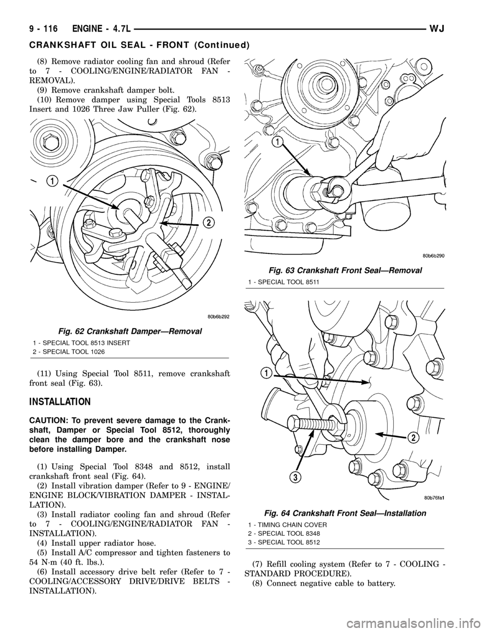
(10) Remove damper using Special Tools 8513
Insert and 1026 Three Jaw Puller (Fig. 62).
(11) Using Special Tool 8511, remove crankshaft
front seal (Fig. 63).
INSTALLATION
CAUTION: To prevent severe damage to the Crank-
shaft, Damper or Special Tool 8512, thoroughly
clean the damper bore and the crankshaft nose
before installing Damper.
(1) Using Special Tool 8348 and 8512, install
crankshaft front seal (Fig. 64).
(2) Install vibration damper (Refer to 9 - ENGINE/
ENGINE BLOCK/VIBRATION DAMPER - INSTAL-
LATION).
(3) Install radiator cooling fan and shroud (Refer
to 7 - COOLING/ENGINE/RADIATOR FAN -
INSTALLATION).
(4) Install upper radiator hose.
(5) Install A/C compressor and tighten fasteners to
54 N´m (40 ft. lbs.).
(6) Install accessory drive belt refer (Refer to 7 -
COOLING/ACCESSORY DRIVE/DRIVE BELTS -
INSTALLATION).(7) Refill cooling system (Refer to 7 - COOLING -
STANDARD PROCEDURE).
(8) Connect negative cable to battery.
Fig. 62 Crankshaft DamperÐRemoval
1 - SPECIAL TOOL 8513 INSERT
2 - SPECIAL TOOL 1026
Fig. 63 Crankshaft Front SealÐRemoval
1 - SPECIAL TOOL 8511
Fig. 64 Crankshaft Front SealÐInstallation
1 - TIMING CHAIN COVER
2 - SPECIAL TOOL 8348
3 - SPECIAL TOOL 8512
9 - 116 ENGINE - 4.7LWJ
CRANKSHAFT OIL SEAL - FRONT (Continued)
Page 1369 of 2199
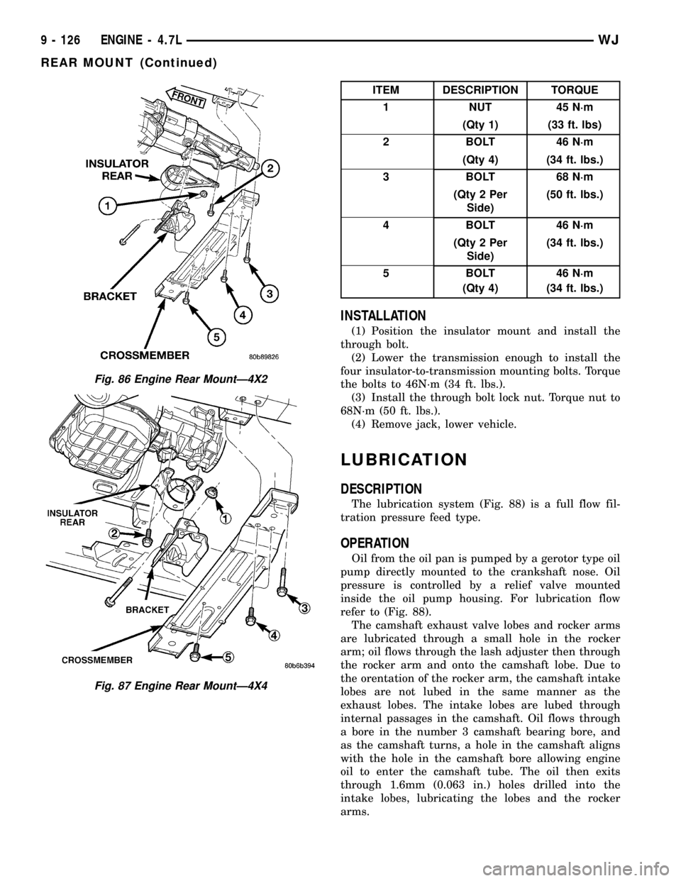
ITEM DESCRIPTION TORQUE
1 NUT 45 N´m
(Qty 1) (33 ft. lbs)
2 BOLT 46 N´m
(Qty 4) (34 ft. lbs.)
3 BOLT 68 N´m
(Qty 2 Per
Side)(50 ft. lbs.)
4 BOLT 46 N´m
(Qty 2 Per
Side)(34 ft. lbs.)
5 BOLT 46 N´m
(Qty 4) (34 ft. lbs.)
INSTALLATION
(1) Position the insulator mount and install the
through bolt.
(2) Lower the transmission enough to install the
four insulator-to-transmission mounting bolts. Torque
the bolts to 46N´m (34 ft. lbs.).
(3) Install the through bolt lock nut. Torque nut to
68N´m (50 ft. lbs.).
(4) Remove jack, lower vehicle.
LUBRICATION
DESCRIPTION
The lubrication system (Fig. 88) is a full flow fil-
tration pressure feed type.
OPERATION
Oil from the oil pan is pumped by a gerotor type oil
pump directly mounted to the crankshaft nose. Oil
pressure is controlled by a relief valve mounted
inside the oil pump housing. For lubrication flow
refer to (Fig. 88).
The camshaft exhaust valve lobes and rocker arms
are lubricated through a small hole in the rocker
arm; oil flows through the lash adjuster then through
the rocker arm and onto the camshaft lobe. Due to
the orentation of the rocker arm, the camshaft intake
lobes are not lubed in the same manner as the
exhaust lobes. The intake lobes are lubed through
internal passages in the camshaft. Oil flows through
a bore in the number 3 camshaft bearing bore, and
as the camshaft turns, a hole in the camshaft aligns
with the hole in the camshaft bore allowing engine
oil to enter the camshaft tube. The oil then exits
through 1.6mm (0.063 in.) holes drilled into the
intake lobes, lubricating the lobes and the rocker
arms.
Fig. 86 Engine Rear MountÐ4X2
Fig. 87 Engine Rear MountÐ4X4
9 - 126 ENGINE - 4.7LWJ
REAR MOUNT (Continued)
Page 1370 of 2199
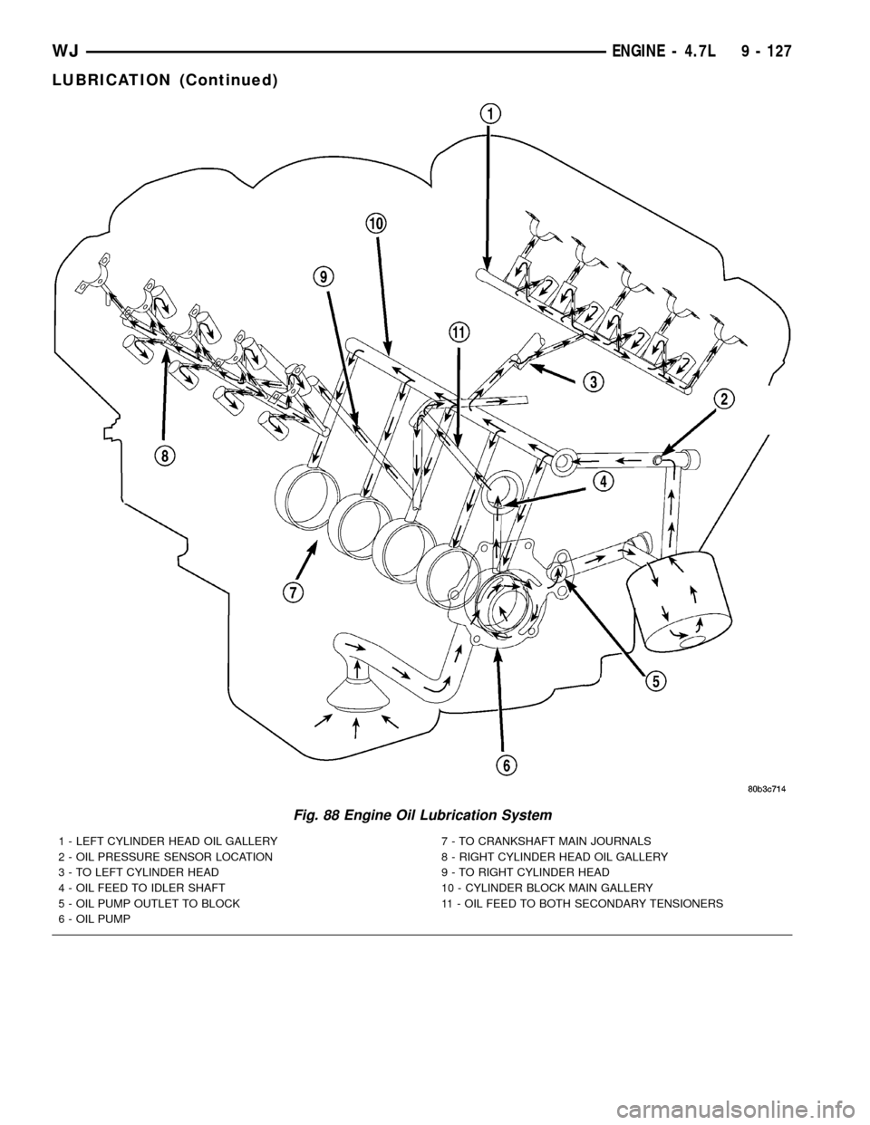
Fig. 88 Engine Oil Lubrication System
1 - LEFT CYLINDER HEAD OIL GALLERY
2 - OIL PRESSURE SENSOR LOCATION
3 - TO LEFT CYLINDER HEAD
4 - OIL FEED TO IDLER SHAFT
5 - OIL PUMP OUTLET TO BLOCK
6 - OIL PUMP7 - TO CRANKSHAFT MAIN JOURNALS
8 - RIGHT CYLINDER HEAD OIL GALLERY
9 - TO RIGHT CYLINDER HEAD
10 - CYLINDER BLOCK MAIN GALLERY
11 - OIL FEED TO BOTH SECONDARY TENSIONERS
WJENGINE - 4.7L 9 - 127
LUBRICATION (Continued)
Page 1375 of 2199
(5) With a wiping cloth, clean the gasket sealing
surface of oil and grime.
INSTALLATION
(1) Lightly lubricate oil filter gasket with engine
oil.
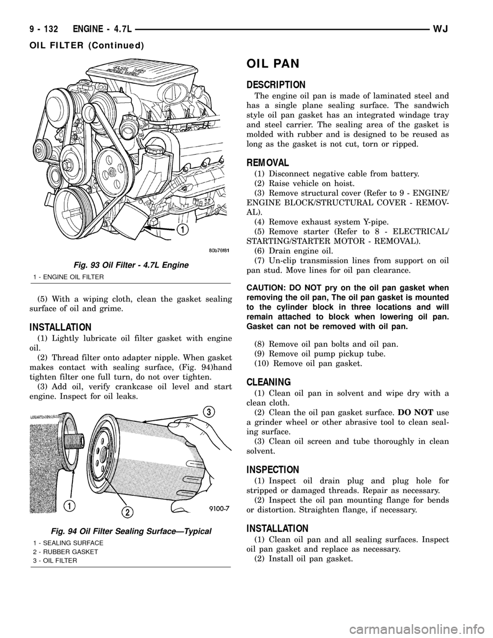
(2) Thread filter onto adapter nipple. When gasket
makes contact with sealing surface, (Fig. 94)hand
tighten filter one full turn, do not over tighten.
(3) Add oil, verify crankcase oil level and start
engine. Inspect for oil leaks.
OIL PAN
DESCRIPTION
The engine oil pan is made of laminated steel and
has a single plane sealing surface. The sandwich
style oil pan gasket has an integrated windage tray
and steel carrier. The sealing area of the gasket is
molded with rubber and is designed to be reused as
long as the gasket is not cut, torn or ripped.
REMOVAL
(1) Disconnect negative cable from battery.
(2) Raise vehicle on hoist.
(3) Remove structural cover (Refer to 9 - ENGINE/
ENGINE BLOCK/STRUCTURAL COVER - REMOV-
AL).
(4) Remove exhaust system Y-pipe.
(5) Remove starter (Refer to 8 - ELECTRICAL/
STARTING/STARTER MOTOR - REMOVAL).
(6) Drain engine oil.
(7) Un-clip transmission lines from support on oil
pan stud. Move lines for oil pan clearance.
CAUTION: DO NOT pry on the oil pan gasket when
removing the oil pan, The oil pan gasket is mounted
to the cylinder block in three locations and will
remain attached to block when lowering oil pan.
Gasket can not be removed with oil pan.
(8) Remove oil pan bolts and oil pan.
(9) Remove oil pump pickup tube.
(10) Remove oil pan gasket.
CLEANING
(1) Clean oil pan in solvent and wipe dry with a
clean cloth.
(2) Clean the oil pan gasket surface.DO NOTuse
a grinder wheel or other abrasive tool to clean seal-
ing surface.
(3) Clean oil screen and tube thoroughly in clean
solvent.
INSPECTION
(1) Inspect oil drain plug and plug hole for
stripped or damaged threads. Repair as necessary.
(2) Inspect the oil pan mounting flange for bends
or distortion. Straighten flange, if necessary.
INSTALLATION
(1) Clean oil pan and all sealing surfaces. Inspect
oil pan gasket and replace as necessary.
(2) Install oil pan gasket.
Fig. 93 Oil Filter - 4.7L Engine
1 - ENGINE OIL FILTER
Fig. 94 Oil Filter Sealing SurfaceÐTypical
1 - SEALING SURFACE
2 - RUBBER GASKET
3 - OIL FILTER
9 - 132 ENGINE - 4.7LWJ
OIL FILTER (Continued)
Page 1376 of 2199

NOTE: When installing oil pan gasket/windage tray,
start four pan bolts at each corner before tightening
oil pickup tube. This will keep pan gasket in align-
ment.
(3) Install oil pump pick-up tube using a new
O-ring. First tighten bolt at O-ring end of tube to 28
N´m (20 ft. lbs.). Tighten remain tube support fasten-
ers to 28 N´m (20 ft. lbs.).
(4) Install oil pan and tighten fasteners to 15 N´m
(11 ft. lbs.) (Fig. 95).
(5) Reconnect transmission oil cooler lines to oil
pan stud bolt.
(6) Install starter (Refer to 8 - ELECTRICAL/
STARTING/STARTER MOTOR - INSTALLATION).
(7) Install exhaust system Y-pipe.
(8) Install structural cover (Refer to 9 - ENGINE/
ENGINE BLOCK/STRUCTURAL COVER - INSTAL-
LATION).
(9) Lower vehicle.
(10) Fill engine with proper amount of oil (Refer to
LUBRICATION & MAINTENANCE/FLUID TYPES -
SPECIFICATIONS).
(11) Connect negative cable to battery.
OIL PRESSURE SENSOR/
SWITCH
DESCRIPTION
The 3±wire, solid-state engine oil pressure sensor
(sending unit) is located in an engine oil pressure
gallery.
OPERATION
The oil pressure sensor uses three circuits. They are:
²A 5±volt power supply from the Powertrain Con-
trol Module (PCM)
²A sensor ground through the PCM's sensor
return
²
A signal to the PCM relating to engine oil pressure
The oil pressure sensor has a 3±wire electrical
function very much like the Manifold Absolute Pres-
sure (MAP) sensor. Meaning different pressures
relate to different output voltages.
A 5±volt supply is sent to the sensor from the PCM
to power up the sensor. The sensor returns a voltage
signal back to the PCM relating to engine oil pres-
sure. This signal is then transferred (bussed) to the
instrument panel on either a CCD or PCI bus circuit
(depending on vehicle line) to operate the oil pressure
gauge and the check gauges lamp. Ground for the
sensor is provided by the PCM through a low-noise
sensor return.
REMOVAL
(1) Disconnect the negative cable from the battery.
(2) Raise vehicle on hoist.
(3) Remove front splash shield.
(4) Disconnect oil pressure sender wire (Fig. 96).
(5) Remove the pressure sender (Fig. 96).
INSTALLATION
(1) Install oil pressure sender.
(2) Connect oil pressure sender wire.
(3) Install front splash shield.
(4) Lower vehicle.
(5) Connect the negative battery cable.
Fig. 95 Oil Pan Tightening Sequence
Fig. 96 Oil Pressure Sending Unit
1 - BELT
2 - OIL PRESSURE SENSOR
3 - OIL FILTER
4 - ELEC. CONNECTOR
WJENGINE - 4.7L 9 - 133
OIL PAN (Continued)
Page 1380 of 2199
(6) Remove accessory drive belt (Refer to 7 -
COOLING/ACCESSORY DRIVE/DRIVE BELTS -
REMOVAL).
(7) Disconnect generator electrical connections.
(8) Unbolt the generator and move it away from
the intake manifold for clearance.
(9) Disconnect air conditioning compressor electri-
cal connections.
(10) Unbolt the air conditioning compressor and
move it away from the intake manifold for clearance.
(11) Disconnect left and right radio suppressor
straps.
(12) Disconnect and remove ignition coil towers
(Refer to 8 - ELECTRICAL/IGNITION CONTROL/
IGNITION COIL - REMOVAL).
(13) Remove top oil dipstick tube retaining bolt
and ground strap.
(14) Bleed pressure from fuel system (Refer to 14 -
FUEL SYSTEM/FUEL DELIVERY - STANDARD
PROCEDURE).
(15) Remove fuel rail (Refer to 14 - FUEL SYS-
TEM/FUEL DELIVERY/FUEL RAIL - REMOVAL).
(16) Remove throttle body assembly and mounting
bracket.
(17) Drain cooling system below coolant tempera-
ture level (Refer to 7 - COOLING - STANDARD
PROCEDURE).
(18) Remove coolant temperature sensor (Refer to
7 - COOLING/ENGINE/ENGINE COOLANT TEMP
SENSOR - REMOVAL).
(19) Remove cowl to hood seal. (Refer to 23 -
BODY/WEATHERSTRIP/SEALS/COWL WEATHER-
STRIP - REMOVAL).
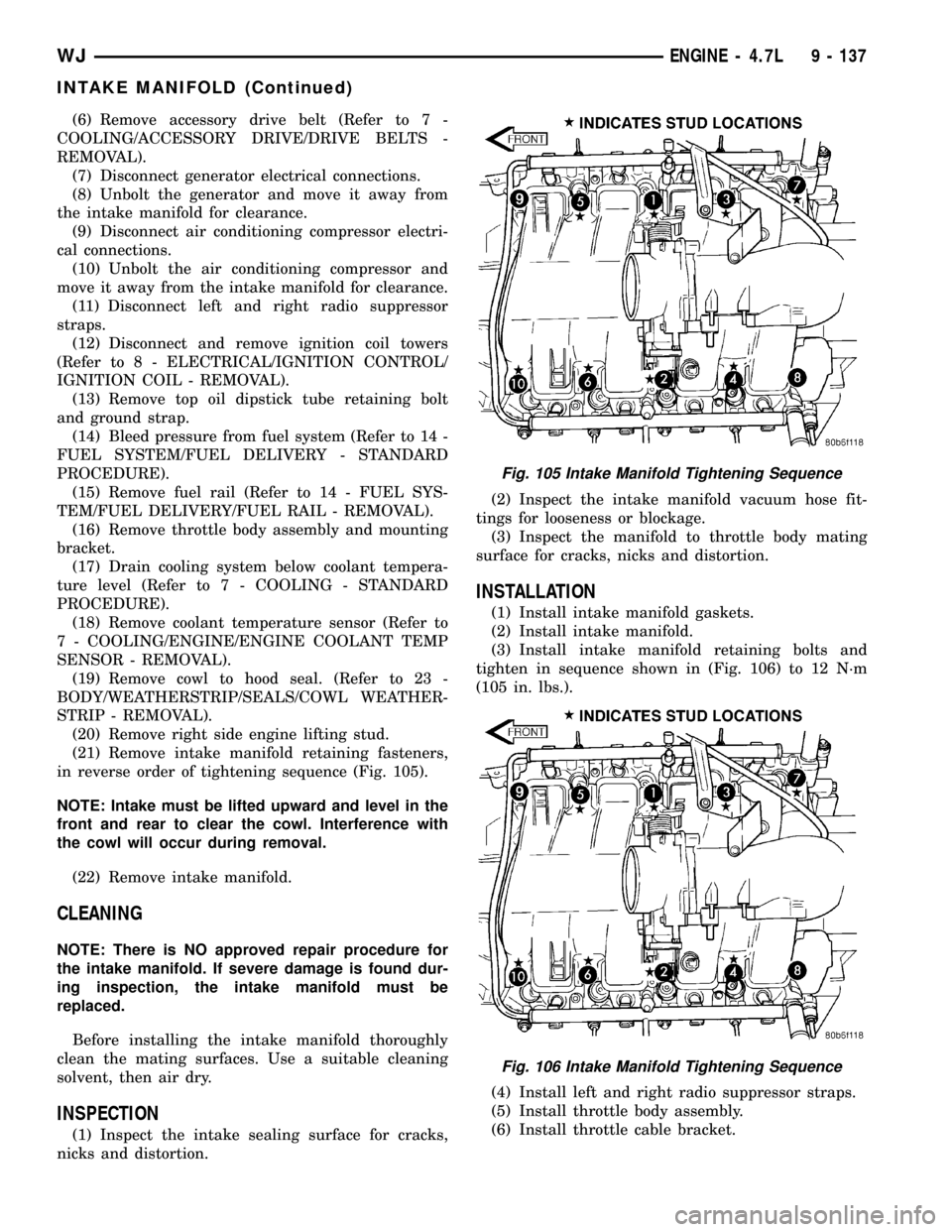
(20) Remove right side engine lifting stud.
(21) Remove intake manifold retaining fasteners,
in reverse order of tightening sequence (Fig. 105).
NOTE: Intake must be lifted upward and level in the
front and rear to clear the cowl. Interference with
the cowl will occur during removal.
(22) Remove intake manifold.
CLEANING
NOTE: There is NO approved repair procedure for
the intake manifold. If severe damage is found dur-
ing inspection, the intake manifold must be
replaced.
Before installing the intake manifold thoroughly
clean the mating surfaces. Use a suitable cleaning
solvent, then air dry.
INSPECTION
(1) Inspect the intake sealing surface for cracks,
nicks and distortion.(2) Inspect the intake manifold vacuum hose fit-
tings for looseness or blockage.
(3) Inspect the manifold to throttle body mating
surface for cracks, nicks and distortion.
INSTALLATION
(1) Install intake manifold gaskets.
(2) Install intake manifold.
(3) Install intake manifold retaining bolts and
tighten in sequence shown in (Fig. 106) to 12 N´m
(105 in. lbs.).
(4) Install left and right radio suppressor straps.
(5) Install throttle body assembly.
(6) Install throttle cable bracket.
Fig. 105 Intake Manifold Tightening Sequence
Fig. 106 Intake Manifold Tightening Sequence
WJENGINE - 4.7L 9 - 137
INTAKE MANIFOLD (Continued)
Page 1381 of 2199

(7) Connect throttle cable and speed control cable
to throttle body.
(8) Install fuel rail (Refer to 14 - FUEL SYSTEM/
FUEL DELIVERY/FUEL RAIL - INSTALLATION).
(9) Install ignition coil towers (Refer to 8 - ELEC-
TRICAL/IGNITION CONTROL/IGNITION COIL -
INSTALLATION).
(10) Install coolant temperature sensor (Refer to 7
- COOLING/ENGINE/ENGINE COOLANT TEMP
SENSOR - INSTALLATION).
(11) Connect electrical connectors for the following
components:
²Manifold Absolute Pressure (MAP) Sensor
²Intake Air Temperature (IAT) Sensor
²Throttle Position (TPS) Sensor
²Coolant Temperature (CTS) Sensor
²Idle Air Control (IAC) Motor
²Ignition coil towers
²Fuel injectors
(12) Install top oil dipstick tube retaining bolt and
ground strap.
(13) Install right side engine lifting stud.
(14) Install generator including electrical connec-
tions (Refer to 8 - ELECTRICAL/CHARGING/GEN-
ERATOR - INSTALLATION).
(15) Connect Vapor purge hose, Brake booster
hose, Speed control servo hose, Positive crankcase
ventilation (PCV) hose.
(16) Install air conditioning compressor including
electrical connections.
(17) Fill cooling system (Refer to 7 - COOLING -
STANDARD PROCEDURE).
(18) Install accessory drive belt (Refer to 7 -
COOLING/ACCESSORY DRIVE/DRIVE BELTS -
INSTALLATION).
(19) Install cowl to hood seal (Refer to 23 - BODY/
WEATHERSTRIP/SEALS/COWL WEATHERSTRIP -
INSTALLATION).
(20) Install air cleaner housing and throttle body
resonator. Tighten resonator bolts 4.5 N´m (40 in.
lbs.).
(21) Connect negative cable to battery.
EXHAUST MANIFOLD - LEFT
DESCRIPTION
The exhaust manifolds are log style with a pat-
ented flow enhancing design to maximize perfor-
mance. The exhaust manifolds are made of high
silicon molybdenum cast iron. A perforated core
graphite exhaust manifold gasket is used to improve
sealing to the cylinder head. The exhaust manifolds
are covered by a three layer laminated heat shield
for thermal protection and noise reduction. The heat
shields are fastened with a torque prevailing nutthat is backed off slightly to allow for the thermal
expansion of the exhaust manifold.
REMOVAL
(1) Disconnect negative cable for battery.
(2) Hoist vehicle.
(3) Disconnect exhaust pipe at manifold.
(4) Lower vehicle.
(5) Remove air cleaner housing and tube.
(6) Remove the front two exhaust heat shield
retaining fasteners. Raise vehicle and remove the
fasteners at rear of heat shield.
(7) Remove heat shield (Fig. 107).
(8) Lower vehicle and remove the upper exhaust
manifold retaining bolts (Fig. 107).
(9) Raise vehicle and remove the lower exhaust
manifold retaining bolts (Fig. 107).
(10) Remove exhaust manifold and gasket (Fig.
107). Manifold is removed from below the engine
compartment.
CLEANING
(1) Clean the exhaust manifold using a suitable
cleaning solvent, then allow to air dry.
(2) Clean all gasket residue from the manifold
mating surface.
INSPECTION
(1) Inspect the exhaust manifold for cracks in the
mating surface and at every mounting bolt hole.
(2) Using a straight edge and a feeler gauge, check
the mating surface for warp and twist.
(3) Inspect the manifold to exhaust pipe mating
surface for cracks, gouges, or other damage that
would prevent sealing.
INSTALLATION
(1) Install exhaust manifold and gasket from below
engine compartment.
(2) Install lower exhaust manifold fasteners (Fig.
107). DO NOT tighten until all fasteners are in
place.
(3) Lower vehicle and install upper exhaust mani-
fold fasteners (Fig. 107). Tighten all manifold bolts
starting at center and working outward to 25 N´m
(18 ft. lbs.).
CAUTION: Over tightening heat shield fasteners,
may cause shield to distort and/or crack.
(4) Install exhaust manifold heat shield (Fig. 107).
Tighten fasteners to 8 N´m (72 in. lbs.), then loosen
45 degrees.
(5) Install air cleaner housing and tube.
(6) Connect exhaust pipe to manifold.
(7) Connect negative cable to battery.
9 - 138 ENGINE - 4.7LWJ
INTAKE MANIFOLD (Continued)