Oil change JEEP GRAND CHEROKEE 2002 WJ / 2.G Repair Manual
[x] Cancel search | Manufacturer: JEEP, Model Year: 2002, Model line: GRAND CHEROKEE, Model: JEEP GRAND CHEROKEE 2002 WJ / 2.GPages: 2199, PDF Size: 76.01 MB
Page 1797 of 2199

Inspect all the valve and plug bores in the valve
body. Use a penlight to view the bore interiors.
Replace the valve body if any bores are distorted or
scored. Inspect all of the valve body springs. The
springs must be free of distortion, warpage or broken
coils.
Trial fit each valve and plug in its bore to check
freedom of operation. When clean and dry, the valves
and plugs should drop freely into the bores.
Valve body bores do not change dimensionally with
use. If the valve body functioned correctly when new,
it will continue to operate properly after cleaning and
inspection. It should not be necessary to replace a
valve body assembly unless it is damaged in han-
dling.
Inspect all the accumulator bores in the valve body.
Use a penlight to view the bore interiors. Replace the
valve body if any bores are distorted or scored.Inspect all of the accumulator springs. The springs
must be free of distortion, warpage or broken coils.
Inspect all the fluid seals on the valve body (Fig.
133). Replace any seals that are cracked, distorted, or
damaged in any way. These seals pass fluid pressure
directly to the clutches. Any pressure leak at these
points, may cause transmission performance prob-
lems.
ASSEMBLY
(1) Lubricate valves, springs, and the housing
valve bores with clean transmission fluid.
(2) Install solenoid switch valve, manual valve,
and the low/reverse switch valve into the valve body.
(3) Install the retainers to hold each valve into the
valve body.
(4) Install the valve body check balls into their
proper locations.
(5) Position the transfer plate onto the valve body.
(6) Install the screws to hold the transfer plate to
the valve body. Tighten the screws to 5.6 N´m (50 in.
lbs.).
(7) Install the accumulator pistons and springs
into the valve body in the location from which they
were removed. Note that all accumulators except the
overdrive have two springs. The overdrive accumula-
tor piston has only one spring.
Fig. 132 Valve Body Components
1 - SOLENOID SWITCH VALVE
2 - MANUAL VALVE
3 - LOW REVERSE SWITCH VALVE
4 - LOW REVERSE ACCUMULATOR
5 - 2ND CLUTCH ACCUMULATOR
6 - UNDERDRIVE ACCUMULATOR
7 - OVERDRIVE ACCUMULATOR
8 - 4TH CLUTCH ACCUMULATOR
9 - CHECK BALLS (7)
Fig. 133 Valve Body Seals
1 - UNDERDRIVE ACCUMULATOR (2 SPRINGS)
2 - 4TH CLUTCH ACCUMULATOR (2 SPRINGS)
3 - 2ND CLUTCH ACCUMULATOR (2 SPRINGS)
4 - LOW REVERSE ACCUMULATOR (2 SPRINGS)
5 - LOW/REVERSE PASSAGE SEAL
6 - 2ND CLUTCH PASSAGE SEAL
7 - 4TH CLUTCH PASSAGE SEAL
8 - OVERDRIVE ACCUMULATOR (1 SPRING)
21 - 278 AUTOMATIC TRANSMISSION - 545RFEWJ
VALVE BODY (Continued)
Page 2162 of 2199

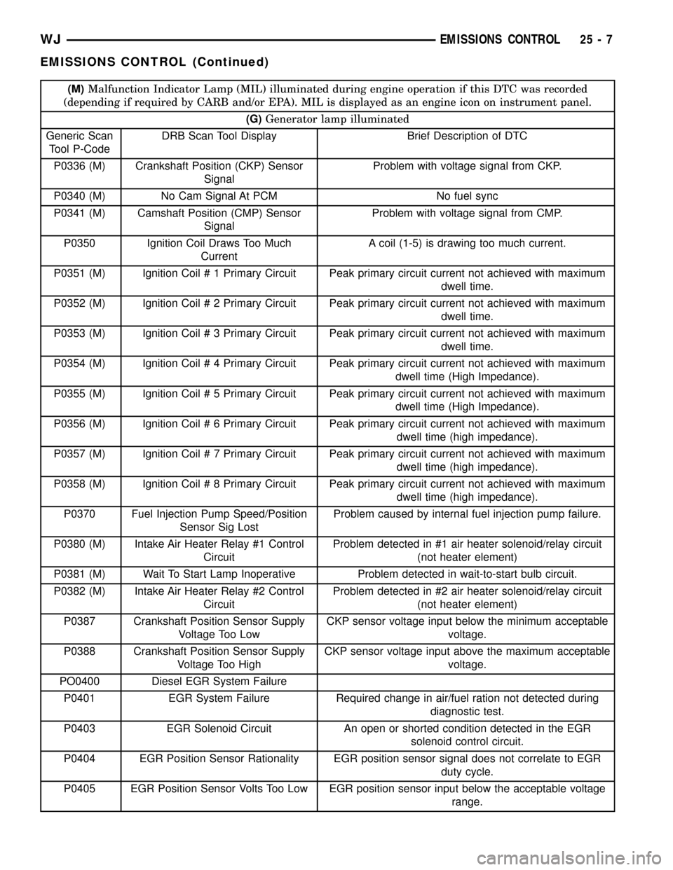
(M)Malfunction Indicator Lamp (MIL) illuminated during engine operation if this DTC was recorded
(depending if required by CARB and/or EPA). MIL is displayed as an engine icon on instrument panel.
(G)Generator lamp illuminated
Generic Scan
Tool P-CodeDRB Scan Tool Display Brief Description of DTC
P0336 (M) Crankshaft Position (CKP) Sensor
SignalProblem with voltage signal from CKP.
P0340 (M) No Cam Signal At PCM No fuel sync
P0341 (M) Camshaft Position (CMP) Sensor
SignalProblem with voltage signal from CMP.
P0350 Ignition Coil Draws Too Much
CurrentA coil (1-5) is drawing too much current.
P0351 (M) Ignition Coil # 1 Primary Circuit Peak primary circuit current not achieved with maximum
dwell time.
P0352 (M) Ignition Coil # 2 Primary Circuit Peak primary circuit current not achieved with maximum
dwell time.
P0353 (M) Ignition Coil # 3 Primary Circuit Peak primary circuit current not achieved with maximum
dwell time.
P0354 (M) Ignition Coil # 4 Primary Circuit Peak primary circuit current not achieved with maximum
dwell time (High Impedance).
P0355 (M) Ignition Coil # 5 Primary Circuit Peak primary circuit current not achieved with maximum
dwell time (High Impedance).
P0356 (M) Ignition Coil # 6 Primary Circuit Peak primary circuit current not achieved with maximum
dwell time (high impedance).
P0357 (M) Ignition Coil # 7 Primary Circuit Peak primary circuit current not achieved with maximum
dwell time (high impedance).
P0358 (M) Ignition Coil # 8 Primary Circuit Peak primary circuit current not achieved with maximum
dwell time (high impedance).
P0370 Fuel Injection Pump Speed/Position
Sensor Sig LostProblem caused by internal fuel injection pump failure.
P0380 (M) Intake Air Heater Relay #1 Control
CircuitProblem detected in #1 air heater solenoid/relay circuit
(not heater element)
P0381 (M) Wait To Start Lamp Inoperative Problem detected in wait-to-start bulb circuit.
P0382 (M) Intake Air Heater Relay #2 Control
CircuitProblem detected in #2 air heater solenoid/relay circuit
(not heater element)
P0387 Crankshaft Position Sensor Supply
Voltage Too LowCKP sensor voltage input below the minimum acceptable
voltage.
P0388 Crankshaft Position Sensor Supply
Voltage Too HighCKP sensor voltage input above the maximum acceptable
voltage.
PO0400 Diesel EGR System Failure
P0401 EGR System Failure Required change in air/fuel ration not detected during
diagnostic test.
P0403 EGR Solenoid Circuit An open or shorted condition detected in the EGR
solenoid control circuit.
P0404 EGR Position Sensor Rationality EGR position sensor signal does not correlate to EGR
duty cycle.
P0405 EGR Position Sensor Volts Too Low EGR position sensor input below the acceptable voltage
range.
WJEMISSIONS CONTROL 25 - 7
EMISSIONS CONTROL (Continued)
Page 2163 of 2199

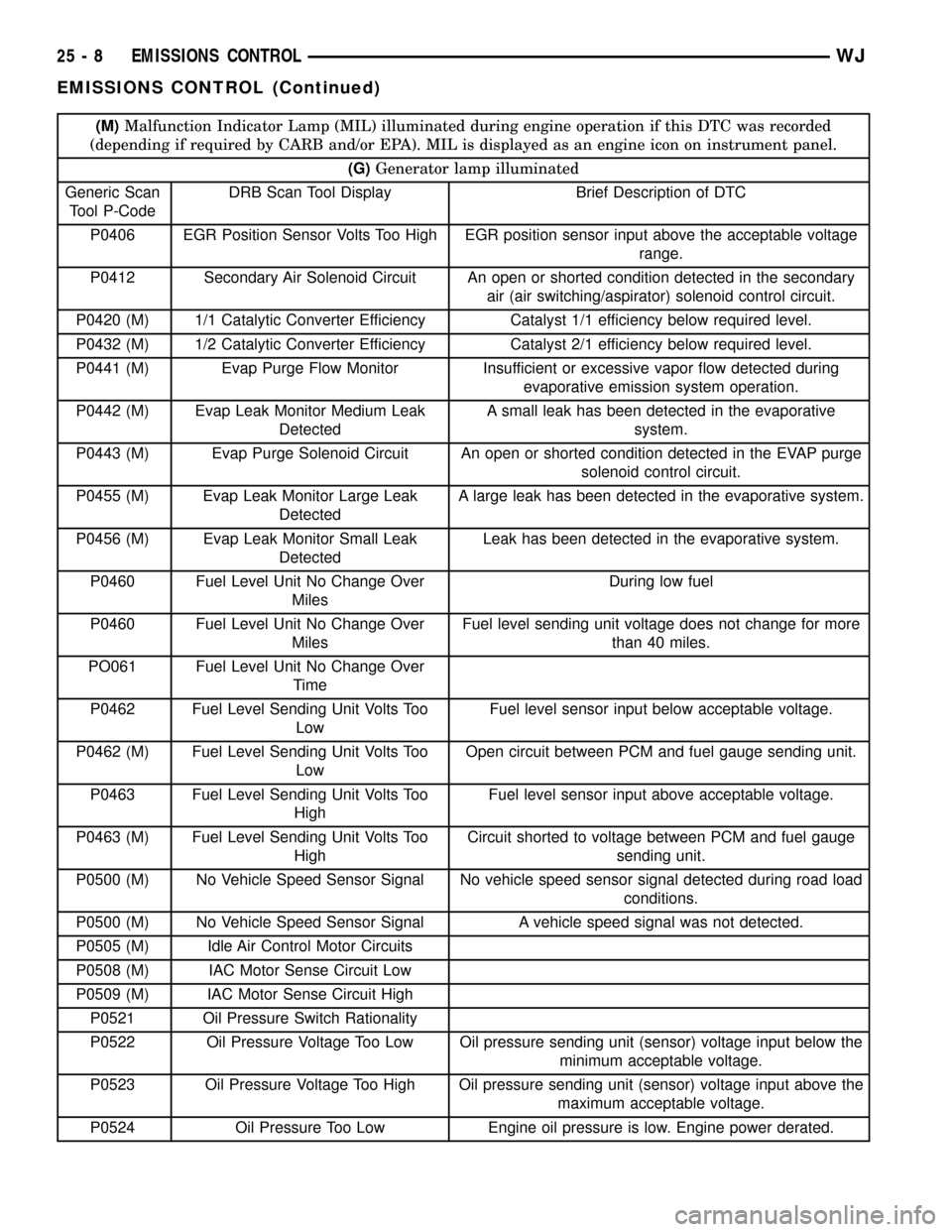
(M)Malfunction Indicator Lamp (MIL) illuminated during engine operation if this DTC was recorded
(depending if required by CARB and/or EPA). MIL is displayed as an engine icon on instrument panel.
(G)Generator lamp illuminated
Generic Scan
Tool P-CodeDRB Scan Tool Display Brief Description of DTC
P0406 EGR Position Sensor Volts Too High EGR position sensor input above the acceptable voltage
range.
P0412 Secondary Air Solenoid Circuit An open or shorted condition detected in the secondary
air (air switching/aspirator) solenoid control circuit.
P0420 (M) 1/1 Catalytic Converter Efficiency Catalyst 1/1 efficiency below required level.
P0432 (M) 1/2 Catalytic Converter Efficiency Catalyst 2/1 efficiency below required level.
P0441 (M) Evap Purge Flow Monitor Insufficient or excessive vapor flow detected during
evaporative emission system operation.
P0442 (M) Evap Leak Monitor Medium Leak
DetectedA small leak has been detected in the evaporative
system.
P0443 (M) Evap Purge Solenoid Circuit An open or shorted condition detected in the EVAP purge
solenoid control circuit.
P0455 (M) Evap Leak Monitor Large Leak
DetectedA large leak has been detected in the evaporative system.
P0456 (M) Evap Leak Monitor Small Leak
DetectedLeak has been detected in the evaporative system.
P0460 Fuel Level Unit No Change Over
MilesDuring low fuel
P0460 Fuel Level Unit No Change Over
MilesFuel level sending unit voltage does not change for more
than 40 miles.
PO061 Fuel Level Unit No Change Over
Time
P0462 Fuel Level Sending Unit Volts Too
LowFuel level sensor input below acceptable voltage.
P0462 (M) Fuel Level Sending Unit Volts Too
LowOpen circuit between PCM and fuel gauge sending unit.
P0463 Fuel Level Sending Unit Volts Too
HighFuel level sensor input above acceptable voltage.
P0463 (M) Fuel Level Sending Unit Volts Too
HighCircuit shorted to voltage between PCM and fuel gauge
sending unit.
P0500 (M) No Vehicle Speed Sensor Signal No vehicle speed sensor signal detected during road load
conditions.
P0500 (M) No Vehicle Speed Sensor Signal A vehicle speed signal was not detected.
P0505 (M) Idle Air Control Motor Circuits
P0508 (M) IAC Motor Sense Circuit Low
P0509 (M) IAC Motor Sense Circuit High
P0521 Oil Pressure Switch Rationality
P0522 Oil Pressure Voltage Too Low Oil pressure sending unit (sensor) voltage input below the
minimum acceptable voltage.
P0523 Oil Pressure Voltage Too High Oil pressure sending unit (sensor) voltage input above the
maximum acceptable voltage.
P0524 Oil Pressure Too Low Engine oil pressure is low. Engine power derated.
25 - 8 EMISSIONS CONTROLWJ
EMISSIONS CONTROL (Continued)