remote JEEP GRAND CHEROKEE 2002 WJ / 2.G Repair Manual
[x] Cancel search | Manufacturer: JEEP, Model Year: 2002, Model line: GRAND CHEROKEE, Model: JEEP GRAND CHEROKEE 2002 WJ / 2.GPages: 2199, PDF Size: 76.01 MB
Page 1185 of 2199

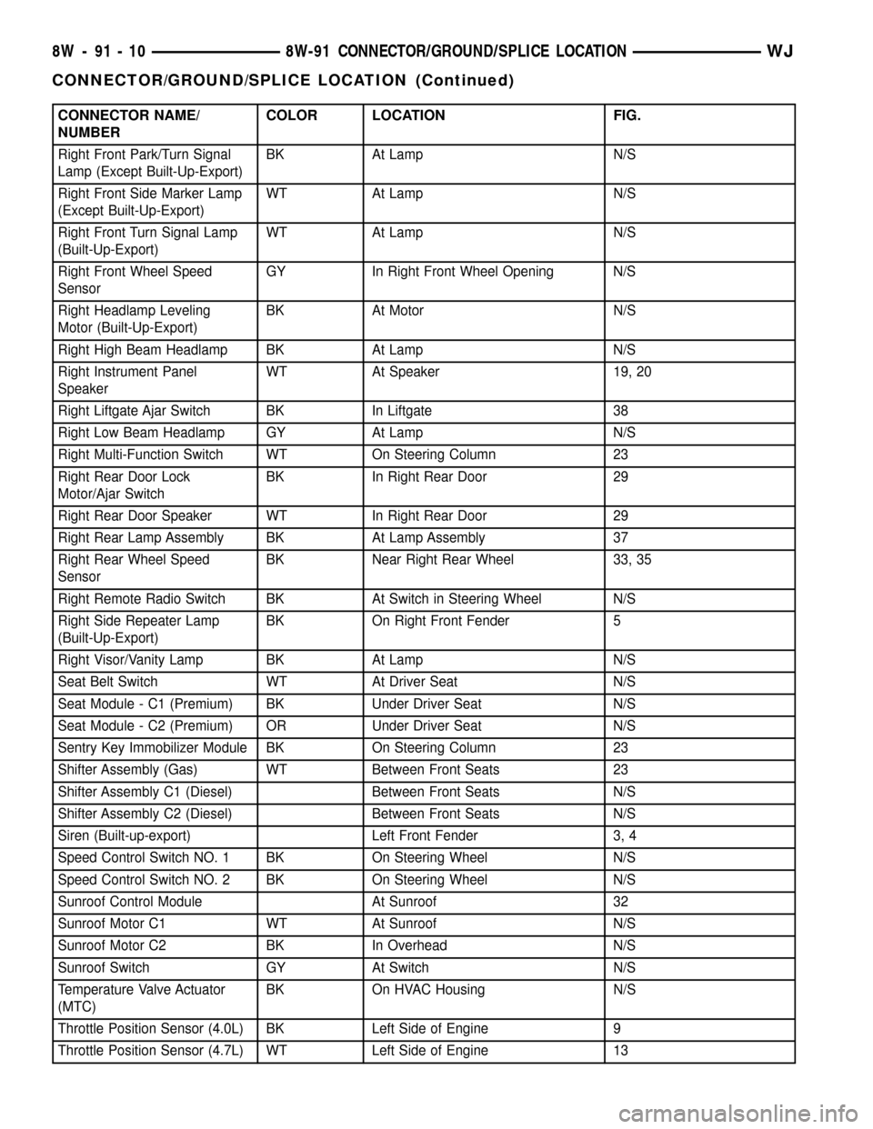
CONNECTOR NAME/
NUMBERCOLOR LOCATION FIG.
Right Front Park/Turn Signal
Lamp (Except Built-Up-Export)BK At Lamp N/S
Right Front Side Marker Lamp
(Except Built-Up-Export)WT At Lamp N/S
Right Front Turn Signal Lamp
(Built-Up-Export)WT At Lamp N/S
Right Front Wheel Speed
SensorGY In Right Front Wheel Opening N/S
Right Headlamp Leveling
Motor (Built-Up-Export)BK At Motor N/S
Right High Beam Headlamp BK At Lamp N/S
Right Instrument Panel
SpeakerWT At Speaker 19, 20
Right Liftgate Ajar Switch BK In Liftgate 38
Right Low Beam Headlamp GY At Lamp N/S
Right Multi-Function Switch WT On Steering Column 23
Right Rear Door Lock
Motor/Ajar SwitchBK In Right Rear Door 29
Right Rear Door Speaker WT In Right Rear Door 29
Right Rear Lamp Assembly BK At Lamp Assembly 37
Right Rear Wheel Speed
SensorBK Near Right Rear Wheel 33, 35
Right Remote Radio Switch BK At Switch in Steering Wheel N/S
Right Side Repeater Lamp
(Built-Up-Export)BK On Right Front Fender 5
Right Visor/Vanity Lamp BK At Lamp N/S
Seat Belt Switch WT At Driver Seat N/S
Seat Module - C1 (Premium) BK Under Driver Seat N/S
Seat Module - C2 (Premium) OR Under Driver Seat N/S
Sentry Key Immobilizer Module BK On Steering Column 23
Shifter Assembly (Gas) WT Between Front Seats 23
Shifter Assembly C1 (Diesel) Between Front Seats N/S
Shifter Assembly C2 (Diesel) Between Front Seats N/S
Siren (Built-up-export) Left Front Fender 3, 4
Speed Control Switch NO. 1 BK On Steering Wheel N/S
Speed Control Switch NO. 2 BK On Steering Wheel N/S
Sunroof Control Module At Sunroof 32
Sunroof Motor C1 WT At Sunroof N/S
Sunroof Motor C2 BK In Overhead N/S
Sunroof Switch GY At Switch N/S
Temperature Valve Actuator
(MTC)BK On HVAC Housing N/S
Throttle Position Sensor (4.0L) BK Left Side of Engine 9
Throttle Position Sensor (4.7L) WT Left Side of Engine 13
8W - 91 - 10 8W-91 CONNECTOR/GROUND/SPLICE LOCATIONWJ
CONNECTOR/GROUND/SPLICE LOCATION (Continued)
Page 1190 of 2199

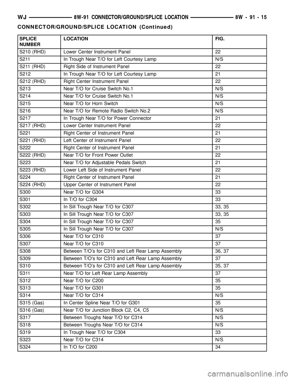
SPLICE
NUMBERLOCATION FIG.
S210 (RHD) Lower Center Instrument Panel 22
S211 In Trough Near T/O for Left Courtesy Lamp N/S
S211 (RHD) Right Side of Instrument Panel 22
S212 In Trough Near T/O for Left Courtesy Lamp 21
S212 (RHD) Right Center Instrument Panel 22
S213 Near T/O for Cruise Switch No.1 N/S
S214 Near T/O for Cruise Switch No.1 N/S
S215 Near T/O for Horn Switch N/S
S216 Near T/O for Remote Radio Switch No.2 N/S
S217 In Trough Near T/O for Power Connector 21
S217 (RHD) Lower Center Instrument Panel 22
S221 Right Center of Instrument Panel 21
S221 (RHD) Left Center of Instrument Panel 22
S222 Right Center of Instrument Panel 21
S222 (RHD) Near T/O for Front Power Outlet 22
S223 Near T/O for Adjustable Pedals Switch 21
S223 (RHD) Lower Left Side of Instrument Panel 22
S224 Right Center of Instrument Panel 21
S224 (RHD) Upper Center of Instrument Panel 22
S300 Near T/O for G304 33
S301 In T/O for C304 33
S302 In Sill Trough Near T/O for C307 33, 35
S303 In Sill Trough Near T/O for C307 33, 35
S304 In Sill Trough Near T/O for C307 35
S305 In Sill Trough Near T/O for C307 N/S
S306 Near T/O for C310 37
S307 Near T/O for C310 37
S308 Between T/O's for C310 and Left Rear Lamp Assembly 36, 37
S309 Between T/O's for C310 and Left Rear Lamp Assembly 37
S310 Between T/O's for C310 and Left Rear Lamp Assembly 35, 37
S311 Near T/O for Left Rear Lamp Assembly 37
S312 Near T/O for C200 35
S313 Near T/O for G301 35
S314 Near T/O for C314 N/S
S315 (Gas) In Center Spline Near T/O for G301 35
S316 (Gas) Near T/O for Junction Block C2, C4, C5 N/S
S317 Between Troughs Near T/O for C314 N/S
S318 Between Troughs Near T/O for C314 N/S
S319 In Trough Near T/O for C304 33
S323 Near T/O for C314 N/S
S324 In T/O for C200 34
WJ8W-91 CONNECTOR/GROUND/SPLICE LOCATION 8W - 91 - 15
CONNECTOR/GROUND/SPLICE LOCATION (Continued)
Page 1191 of 2199

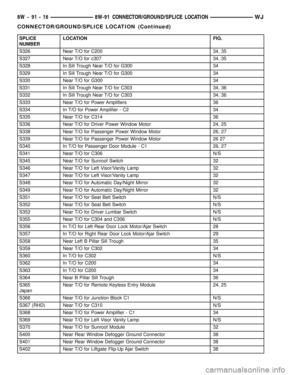
SPLICE
NUMBERLOCATION FIG.
S326 Near T/O for C200 34, 35
S327 Near T/O for c307 34, 35
S328 In Sill Trough Near T/O for G300 34
S329 In Sill Trough Near T/O for G300 34
S330 Near T/O for G300 34
S331 In Sill Trough Near T/O for C303 34, 36
S332 In Sill Trough Near T/O for C303 34, 36
S333 Near T/O for Power Amplifiers 36
S334 In T/O for Power Amplifier - C2 34
S335 Near T/O for C314 36
S336 Near T/O for Driver Power Window Motor 24, 25
S338 Near T/O for Passenger Power Window Motor 26, 27
S339 Near T/O for Passenger Power Window Motor 26 27
S340 In T/O for Passenger Door Module - C1 26, 27
S341 Near T/O for C306 N/S
S345 Near T/O for Sunroof Switch 32
S346 Near T/O for Left Visor/Vanity Lamp 32
S347 Near T/O for Left Visor/Vanity Lamp 32
S348 Near T/O for Automatic Day/Night Mirror 32
S349 Near T/O for Automatic Day/Night Mirror 32
S351 Near T/O for Seat Belt Switch N/S
S352 Near T/O for Seat Belt Switch N/S
S353 Near T/O for Driver Lumbar Switch N/S
S355 Near T/O for C304 and C306 N/S
S356 In T/O for Left Rear Door Lock Motor/Ajar Switch 28
S357 In T/O for Right Rear Door Lock Motor/Ajar Switch 29
S358 Near Left B Pillar Sill Trough 35
S359 Near T/O for C302 34
S360 In T/O for C302 N/S
S362 In T/O for C200 34
S363 In T/O for C200 34
S364 Near B Pillar Sill Trough 36
S365
JapanNear T/O for Remote Keyless Entry Module 24, 25
S366 Near T/O for Junction Block C1 N/S
S367 (RHD) Near T/O for C310 N/S
S368 Near T/O for Power Amplifier - C1 34
S369 Near T/O for Left Visor Vanity Lamp N/S
S370 Near T/O for Sunroof Module 32
S400 Near Rear Window Defogger Ground Connector 38
S401 Near Rear Window Defogger Ground Connector 38
S402 Near T/O for Liftgate Flip-Up Ajar Switch 38
8W - 91 - 16 8W-91 CONNECTOR/GROUND/SPLICE LOCATIONWJ
CONNECTOR/GROUND/SPLICE LOCATION (Continued)
Page 1425 of 2199

The regulator is calibrated to maintain fuel system
operating pressure of approximately 339 kPa 34
kPa (49.2 psi 5 psi) at the fuel injectors. It contains
a diaphragm, calibrated springs and a fuel return
valve. The internal fuel filter is also part of the
assembly.
Fuel is supplied to the filter/regulator by the elec-
tric fuel pump. The regulator acts as a check valve to
maintain some fuel pressure when the engine is not
operating. This will help to start the engine. A second
check valve is located at the outlet end of the electric
fuel pump.
If fuel pressure at the pressure regulator exceeds
approximately 49 psi, an internal diaphragm closes.
Excess fuel is then routed into a separate fuel return
line and returned to the fuel tank through the top of
the fuel pump module.
Both fuel filters (at bottom of fuel pump module
and within fuel pressure regulator) are designed for
extended service. They do not require normal sched-
uled maintenance. Filters should only be replaced if
a diagnostic procedure indicates to do so.
REMOVAL
The combination Fuel Filter/Fuel Pressure Regula-
tor is remotely mounted to the vehicle body, above
the rear axle and near the front of the fuel tank (Fig.
4) or (Fig. 5).
(1) Perform Fuel System Pressure Release Proce-
dure.
(2) Disconnect negative battery cable at battery.
(3) Raise vehicle.
(4) Clean area around 3 filter/regulator fittings.
(5) Disconnect fuel supply, fuel return and fuel
pressure lines at filter/regulator (Fig. 4) . Refer to
Quick-Connect Fittings.
(6) Remove 2 mounting bolts (Fig. 5) and remove
filter/regulator.
INSTALLATION
The combination Fuel Filter/Fuel Pressure Regula-
tor is remotely mounted to the vehicle body, above
the rear axle and near the front of the fuel tank (Fig.
4) or (Fig. 5).
(1) Before installing filter/regulator, be sure all fit-
tings are cleaned of all dirt and contaminants.
(2) Be sure o-ring is positioned into fuel return fit-
ting in filter/regulator.
Fig. 3 Fuel Filter/Fuel Pressure Regulator Location
1 - FUEL SUPPLY LINE (TO FUEL RAIL)
2 - EVAP LINE
3 - FUEL RETURN LINE (MALE)
4 - FUEL PRESSURE LINE (FEMALE)
5 - FUEL FILTER/PRESSURE REGULATOR
6 - FUEL TANK
Fig. 4 Fuel Filter/Fuel Pressure Regulator Location
1 - FUEL SUPPLY LINE (TO FUEL RAIL)
2 - EVAP LINE
3 - FUEL RETURN LINE (MALE)
4 - FUEL PRESSURE LINE (FEMALE)
5 - FUEL FILTER/PRESSURE REGULATOR
6 - FUEL TANK
14 - 6 FUEL DELIVERYWJ
FUEL FILTER/PRESSURE REGULATOR (Continued)
Page 1871 of 2199

TIRE PRESSURE MONITORING
DESCRIPTION
The EVIC will monitor the tire pressure signals
from the five tire sensors and determine if any tire
has gone below the low pressure threshold or raised
above the high pressure threshold. Refer to the table
below.
LOW TIRE PRESSURE THRESHOLDS
SYSTEM STATUS
INDICATORTIRE PRESSURE
ON 179 kPa (26 PSI)
OFF 214 kPa (31 PSI)
HIGH TIRE PRESSURE THRESHOLDS
SYSTEM STATUS
INDICATORTIRE PRESSURE
ON 310 kPa (45 PSI)
OFF 276 kPa (40 PSI)
The Remote Tire Pressure Monitors (RTPM) are
not internally serviceable. For a Sensor Failure or
Low Battery fault, the RTPM must be replaced.
OPERATION
If equipped with the Tire Pressure Monitoring Sys-
tem, each of the vehicle's five wheels will have a
valve stem with a pressure sensor and radio trans-
mitter built in. Signals from the tire pressure sensors
are received and interpreted by the Electronic Vehi-
cle Information Center (EVIC). A sensor in a
mounted wheel will broadcast its detected pressure
once per minute when the vehicle is moving faster
than 40 km/h (25 mph). The spare tire sensor will
broadcast once every hour. Each sensor's broadcast is
uniquely coded so that the EVIC can determine loca-
tion. The individual tire pressures can be displayed
graphically on the EVIC
DIAGNOSIS AND TESTING - TIRE PRESSURE
MONITORING SYSTEM
All Tire Pressure Monitoring System Faults are
specific to one location. If a9BATTERY LOW9or
9SENSOR FAILURE9fault is detected, the location
will be displayed. The appropriate sensor/transmitter
can then be replaced. If a single sensor/transmitter
cannot be detected by the EVIC, replace that sensor
transmitter. If none of the sensors/transmitters can
be detected, refer to symptoms in the EVIC section.
For additional system description and diagnosis,
refer to Tire Pressure Monitoring in the Body Diag-
nostic manual.
SENSOR
REMOVAL - TIRE PRESSURE SENSOR/
TRANSMITTER
(1) Remove the tire/wheel from the vehicle.
CAUTION: When removing the stick on balancing
weights from the wheel, do not use an abrasive
cleaner or a cleaner which will damage the protec-
tive finish on the wheel.
(2) Remove the balancing weights from the wheel.
NOTE: The cap used on this valve stem contains an
O-ring seal to prevent contamination and moisture
from entering the valve stem. Retain this valve stem
cap for re-use. Do not substitute a regular valve
stem cap in its place.
(3) Remove the cap from the valve stem.
NOTE: The valve stem used on this vehicle is made
of aluminum and the core is nickel plated brass.
The original valve stem core must be reinstalled
and not substituted for a valve stem core made of a
different material. This is required to prevent corro-
sion in the valve stem caused by the different met-
als.
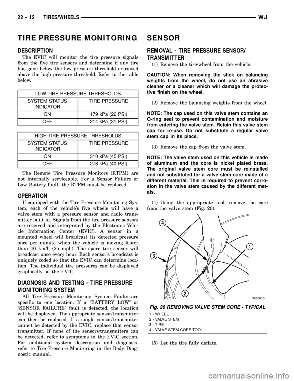
(4) Using the appropriate tool, remove the core
from the valve stem (Fig. 20).
(5) Let the tire fully deflate.
Fig. 20 REMOVING VALVE STEM CORE - TYPICAL
1 - WHEEL
2 - VALVE STEM
3 - TIRE
4 - VALVE STEM CORE TOOL
22 - 12 TIRES/WHEELSWJ