Oil drain JEEP GRAND CHEROKEE 2002 WJ / 2.G Repair Manual
[x] Cancel search | Manufacturer: JEEP, Model Year: 2002, Model line: GRAND CHEROKEE, Model: JEEP GRAND CHEROKEE 2002 WJ / 2.GPages: 2199, PDF Size: 76.01 MB
Page 1793 of 2199

be in the downshifted position, thus directing fluid to
the L/R clutch circuit. In 2nd, 3rd, 4th, and fifth
gears, the solenoid switch valve will be in the
upshifted position and directs the fluid into the
torque converter clutch (TCC) circuit.
When shifting into 1st gear, a special hydraulic
sequence is performed to ensure SSV movement into
the downshifted position. The L/R pressure switch is
monitored to confirm SSV movement. If the move-
ment is not confirmed (the L/R pressure switch does
not close), 2nd gear is substituted for 1st. A DTC will
be set after three unsuccessful attempts are made to
get into 1st gear in one given key start.
MANUAL VALVE
The manual valve is a relay valve. The purpose of
the manual valve is to direct fluid to the correct cir-
cuit needed for a specific gear or driving range. The
manual valve, as the name implies, is manually oper-
ated by the driver with a lever located on the top of
the valve body. The valve is connected mechanically
by a cable to the gearshift mechanism. The valve is
held in each of its positions by a roller detent spring
(Fig. 123) that engages the ªroostercombº of the TRS
selector plate.
LOW/REVERSE SWITCH VALVE
The low/reverse switch valve allows the low/reverse
clutch to be operated by either the LR/CC solenoid or
the MS solenoid.
REMOVAL
The valve body can be removed for service without
having to remove the transmission assembly.
The valve body can be disassembled for cleaning
and inspection of the individual components. (Refer
to 21 - TRANSMISSION/TRANSAXLE/AUTOMATIC
- 45RFE/VALVE BODY - DISASSEMBLY)
(1) Shift transmission into PARK.
(2) Raise vehicle.
(3) Disconnect wires at the solenoid and pressure
switch assembly connector.
(4) Position drain pan under transmission oil pan.
(5) Remove transmission oil pan.
(6) Remove the primary oil filter from valve body.
(Fig. 124)
Fig. 123 TRS Selector Plate and Detent Spring
1 - TRS SELECTOR PLATE
2 - DETENT SPRING
3 - CLUTCH PASSAGE SEALS
Fig. 124 Remove Primary Oil Filter
1 - PRIMARY OIL FILTER
2 - COOLER RETURN FILTER
3 - COOLER RETURN FILTER BYPASS VALVE
4 - VALVE BODY
21 - 274 AUTOMATIC TRANSMISSION - 545RFEWJ
VALVE BODY (Continued)
Page 1814 of 2199

REAR OUTPUT SHAFT/YOKE/DRIVE CHAIN
Check condition of the seal contact surfaces of the
yoke slinger (Fig. 49). This surface must be clean and
smooth to ensure proper seal life. Replace the yoke
nut and seal washer as neither part should be
reused.
Inspect the shaft threads, sprocket teeth, and bear-
ing surfaces. Minor nicks on the teeth can be
smoothed with an oilstone. Use 320-400 grit emery to
smooth minor scratches on the shaft bearing sur-
faces. Rough threads on the shaft can be chased if
necessary. Replace the shaft if the threads are dam-
aged, bearing surfaces are scored, or if any sprocket
teeth are cracked or broken.
Examine the drive chain and shaft bearings.
Replace the chain and both sprockets if the chain is
stretched, distorted, or if any of the links bind.
Replace the bearings if rough, or noisy.
LOW RANGE ANNULUS GEAR
Inspect annulus gear condition carefully. The gear
is only serviced as part of the front case. If the gear
is damaged, it will be necessary to replace the gear
and front case as an assembly. Do not attempt to
remove the gear (Fig. 50)
FRONT-REAR CASES AND FRONT RETAINER
Inspect the cases and retainer for wear and dam-
age. Clean the sealing surfaces with a scraper and
3M all purpose cleaner. This will ensure proper
sealer adhesion at assembly. Replace the input
retainer seal; do not reuse it.Check case condition. If leaks were a problem, look
for gouges and severe scoring of case sealing sur-
faces. Also make sure the front case mounting studs
are in good condition.
Check the front case mounting studs and vent
tube. The tube can be secured with LoctiteŸ 271 or
680 if loose. The stud threads can be cleaned up with
a die if necessary. Also check condition of the fill/
drain plug threads in the rear case. The threads can
be repaired with a thread chaser or tap if necessary.
Or the threads can be repaired with HelicoilŸ stain-
less steel inserts if required.
OIL PUMP/OIL PICKUP
Examine the oil pump pickup parts. Replace the
pump if any part appears to be worn or damaged. Do
not disassemble the pump as individual parts are not
available. The pump is only available as a complete
assembly. The pickup screen, hose, and tube are the
only serviceable parts and are available separately.
ASSEMBLY
Lubricate transfer case components with automatic
transmission fluid or petroleum jelly (where indi-
cated) during assembly.
CAUTION: The bearing bores in various transfer
case components contain oil feed holes. Make sure
replacement bearings do not block the holes.
Fig. 49 Seal Contact Surface Of Yoke Slinger
1 - FRONT SLINGER (PART OF YOKE)
2 - SEAL CONTACT SURFACE MUST BE CLEAN AND SMOOTH
Fig. 50 Low Range Annulus Gear
1 - FRONT CASE
2 - LOW RANGE ANNULUS GEAR
WJTRANSFER CASE - NV242 21 - 295
TRANSFER CASE - NV242 (Continued)
Page 1827 of 2199

SPECIFICATIONS
TRANSFER CASE - NV242
TORQUE SPECIFICATIONS
DESCRIPTION N´m Ft. Lbs. In. Lbs.
Plug, Detent 16-24 11.8-17.7 -
Bolt, Diff. Case 17-27 12.5-19.9 -
Plug, Drain/Fill 20-34 15-25 -
Bolt, Front Brg. Retainer 16-27 11.8-19.9 -
Bolt, Case Half 35-46 25.8-33.9 -
Nut, Front Yoke 122-176 90-130 -
Screw, Oil Pump 1.2-1.8 - 12-15
Nut, Range Lever 27-34 19.9-25 -
Bolt, Rear Retainer 35-46 25.8-33.9 -
Nuts, Mounting 35 25.8 -
Bolts, U-Joint 19 14 -
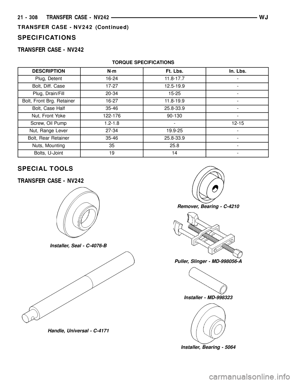
SPECIAL TOOLS
TRANSFER CASE - NV242
Installer, Seal - C-4076-B
Handle, Universal - C-4171
Remover, Bearing - C-4210
Puller, Slinger - MD-998056-A
Installer - MD-998323
Installer, Bearing - 5064
21 - 308 TRANSFER CASE - NV242WJ
TRANSFER CASE - NV242 (Continued)
Page 1835 of 2199

OPERATION
Under normal driving conditions, the system oper-
ates conventionally, and the majority of available
torque is applied to the rear wheels. However, when
front-to-rear wheel speed variations exist, the pro-
gressive differential transfers torque to the axle with
the better traction, thus minimizing wheel spin and
maximizing control.
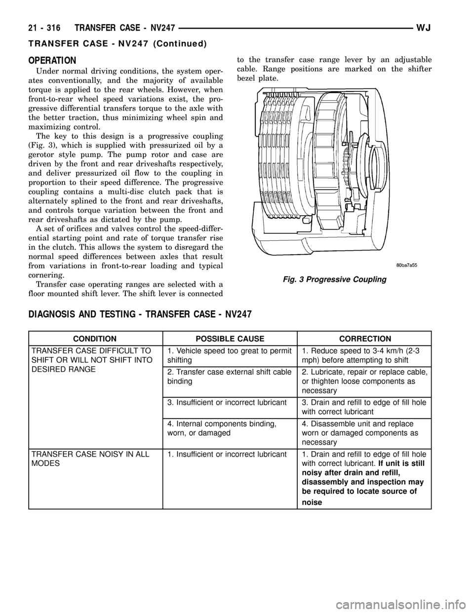
The key to this design is a progressive coupling
(Fig. 3), which is supplied with pressurized oil by a
gerotor style pump. The pump rotor and case are
driven by the front and rear driveshafts respectively,
and deliver pressurized oil flow to the coupling in
proportion to their speed difference. The progressive
coupling contains a multi-disc clutch pack that is
alternately splined to the front and rear driveshafts,
and controls torque variation between the front and
rear driveshafts as dictated by the pump.
A set of orifices and valves control the speed-differ-
ential starting point and rate of torque transfer rise
in the clutch. This allows the system to disregard the
normal speed differences between axles that result
from variations in front-to-rear loading and typical
cornering.
Transfer case operating ranges are selected with a
floor mounted shift lever. The shift lever is connectedto the transfer case range lever by an adjustable
cable. Range positions are marked on the shifter
bezel plate.
DIAGNOSIS AND TESTING - TRANSFER CASE - NV247
CONDITION POSSIBLE CAUSE CORRECTION
TRANSFER CASE DIFFICULT TO
SHIFT OR WILL NOT SHIFT INTO
DESIRED RANGE1. Vehicle speed too great to permit
shifting1. Reduce speed to 3-4 km/h (2-3
mph) before attempting to shift
2. Transfer case external shift cable
binding2. Lubricate, repair or replace cable,
or thighten loose components as
necessary
3. Insufficient or incorrect lubricant 3. Drain and refill to edge of fill hole
with correct lubricant
4. Internal components binding,
worn, or damaged4. Disassemble unit and replace
worn or damaged components as
necessary
TRANSFER CASE NOISY IN ALL
MODES1. Insufficient or incorrect lubricant 1. Drain and refill to edge of fill hole
with correct lubricant.If unit is still
noisy after drain and refill,
disassembly and inspection may
be required to locate source of
noise
Fig. 3 Progressive Coupling
21 - 316 TRANSFER CASE - NV247WJ
TRANSFER CASE - NV247 (Continued)
Page 2152 of 2199

REFRIGERANT
DESCRIPTION
The refrigerant used in this air conditioning sys-
tem is a HydroFluoroCarbon (HFC), type R-134a.
Unlike R-12, which is a ChloroFluoroCarbon (CFC),
R-134a refrigerant does not contain ozone-depleting
chlorine. R-134a refrigerant is a non-toxic, non-flam-
mable, clear, and colorless liquefied gas.
Even though R-134a does not contain chlorine, it
must be reclaimed and recycled just like CFC-type
refrigerants. This is because R-134a is a greenhouse
gas and can contribute to global warming.
OPERATION
R-134a refrigerant is not compatible with R-12
refrigerant in an air conditioning system. Even a
small amount of R-12 added to an R-134a refrigerant
system will cause compressor failure, refrigerant oil
sludge or poor air conditioning system performance.
In addition, the PolyAlkylene Glycol (PAG) synthetic
refrigerant oils used in an R-134a refrigerant system
are not compatible with the mineral-based refriger-
ant oils used in an R-12 refrigerant system.
R-134a refrigerant system service ports, service
tool couplers and refrigerant dispensing bottles have
all been designed with unique fittings to ensure that
an R-134a system is not accidentally contaminated
with the wrong refrigerant (R-12). There are also
labels posted in the engine compartment of the vehi-
cle and on the compressor identifying to service tech-
nicians that the air conditioning system is equipped
with R-134a.
REFRIGERANT OIL
DESCRIPTION
The refrigerant oil used in R-134a refrigerant sys-
tems is a synthetic-based, PolyAlkylene Glycol (PAG),
wax-free lubricant. Mineral-based R-12 refrigerant
oils are not compatible with PAG oils, and should
never be introduced to an R-134a refrigerant system.
There are different PAG oils available, and each
contains a different additive package. The 10PA17
compressor used in this vehicle is designed to use an
ND8 PAG refrigerant oil. Use only refrigerant oil of
this same type to service the refrigerant system.
OPERATION
After performing any refrigerant recovery or recy-
cling operation, always replenish the refrigerant sys-
tem with the same amount of the recommended
refrigerant oil as was removed. Too little refrigerant
oil can cause compressor damage, and too much can
reduce air conditioning system performance.PAG refrigerant oil is much more hygroscopic than
mineral oil, and will absorb any moisture it comes
into contact with, even moisture in the air. The PAG
oil container should always be kept tightly capped
until it is ready to be used. After use, recap the oil
container immediately to prevent moisture contami-
nation.
STANDARD PROCEDURE - REFRIGERANT OIL
LEVEL
When an air conditioning system is assembled at
the factory, all components except the compressor are
refrigerant oil free. After the refrigerant system has
been charged and operated, the refrigerant oil in the
compressor is dispersed throughout the refrigerant
system. The accumulator, evaporator, condenser, and
compressor will each retain a significant amount of
the needed refrigerant oil.
It is important to have the correct amount of oil in
the refrigerant system. This ensures proper lubrica-
tion of the compressor. Too little oil will result in
damage to the compressor. Too much oil will reduce
the cooling capacity of the air conditioning system.
It will not be necessary to check the oil level in the
compressor or to add oil, unless there has been an oil
loss. An oil loss may occur due to a rupture or leak
from a refrigerant line, a connector fitting, a compo-
nent, or a component seal. If a leak occurs, add 30
milliliters (1 fluid ounce) of refrigerant oil to the
refrigerant system after the repair has been made.
Refrigerant oil loss will be evident at the leak point
by the presence of a wet, shiny surface around the
leak.
Refrigerant oil must be added when a accumulator,
evaporator coil, or condenser are replaced. See the
Refrigerant Oil Capacities chart. When a compressor
is replaced, the refrigerant oil must be drained from
the old compressor and measured. Drain all of the
refrigerant oil from the new compressor, then fill the
new compressor with the same amount of refrigerant
oil that was drained out of the old compressor.
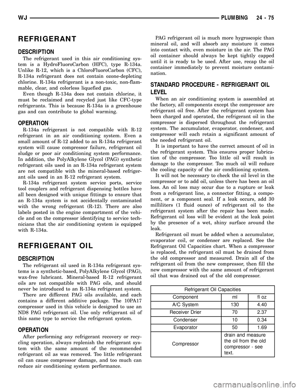
Refrigerant Oil Capacities
Component ml fl oz
A/C System 130 4.40
Receiver Drier 70 2.37
Condenser 10 0.34
Evaporator 50 1.69
Compressordrain and measure
the oil from the old
compressor - see
text.
WJPLUMBING 24 - 75
Page 2153 of 2199

VISCOUS HEATER
DESCRIPTION
DESCRIPTION
The diesel engine has an engine mounted mechan-
ical device called a Viscous Heater that is used to
heat the coolant coming from the engine to the
heater core. The Viscous Heater is driven by the
engine fan belt and has a electro-mechanical clutch
which is controlled by the HVAC control unit.
DESCRIPTION - VISCOUS HEATER CLUTCH
The basic viscous heater clutch assembly consists
of a stationary electromagnetic coil, a hub bearing
and pulley assembly and a clutch plate. The electro-
magnetic coil unit and the hub bearing and pulley
assembly are each retained on the nose of the com-
pressor front housing with snap rings (Fig. 17). The
clutch plate is keyed to the viscous heater shaft and
secured with a nut. These components provide the
means to engage and disengage the viscous heater
from the engine accessory drive belt.
OPERATION
OPERATION - VISCOUS HEATER
The Viscous Heater is driven by the engine fan
belt. The Viscous Heater has an electro-mechanical
clutch that receives a signal from the HVAC control
head and the Viscous Heater controller that ener-
gizes and engages the clutch. Once engaged theclutch allows the Viscous Heater to increase the tem-
perature of the coolant flowing to the heater core,
which provides heat the passenger compartment
quicker than normal engines without the Viscous
Heater. The Viscous Heater generates heat by means
of friction which heats a special Silicon Oil within its
housing which is then transferred to the engine cool-
ant when the coolant passes over fins within the
pump. Please note that the coolant is isolated from
the silicon oil within the pump housing. When
demand for passenger compartment heat decreases
the Viscous Heater clutch will receive an input from
the Viscous heater controller to disengage.
OPERATION - VISCOUS HEATER CLUTCH
When the clutch coil is energized, it magnetically
draws the clutch into contact with the pulley and
drives the viscous heater shaft. When the coil is not
energized the pulley freewheels on the clutch hub
bearing, which is part of the pulley. The viscous
heater clutch and coil are the only serviced parts on
the viscous heater assembly. If the viscous heater is
inoperative or damaged the entire assembly must be
replaced. The viscous heater clutch engagement is
controlled by several components: the viscous heater
controller, the engine powertrain control module and
the HVAC control head.
REMOVAL
REMOVAL - VISCOUS HEATER
(1) Drain the engine coolant(Refer to 7 - COOL-
ING/ENGINE - STANDARD PROCEDURE).
(2) Remove the engine accessory drive belt(Refer to
7 - COOLING/ACCESSORY DRIVE/DRIVE BELTS -
REMOVAL).
(3) Remove the heater hose clamps at the Viscous
Heater.
(4) Remove the heater hoses from the Viscous
Heater.
(5) Unplug the Viscous Heater clutch electrical
connector.
(6) Remove the bolts holding the Viscous Heater to
the mounting bracket.
(7) Remove the Viscous Heater from the vehicle.
REMOVAL - VISCOUS HEATER CLUTCH
(1) The viscous heater clutch can be serviced in
the vehicle and the cooling system does not have to
be drained.
(2) Disconnect and isolate the battery negative
cable.
(3) Remove the serpentine drive belt(Refer to 7 -
COOLING/ACCESSORY DRIVE/DRIVE BELTS -
REMOVAL).
Fig. 17 CLUTCH ASSEMBLY- typical
1 - CLUTCH PLATE
2 - SHAFT KEY
3 - PULLEY
4 - COIL
5 - CLUTCH SHIMS
6 - SNAP RING
7 - SNAP RING
24 - 76 PLUMBINGWJ