Turn signal switch JEEP GRAND CHEROKEE 2002 WJ / 2.G Manual PDF
[x] Cancel search | Manufacturer: JEEP, Model Year: 2002, Model line: GRAND CHEROKEE, Model: JEEP GRAND CHEROKEE 2002 WJ / 2.GPages: 2199, PDF Size: 76.01 MB
Page 1137 of 2199
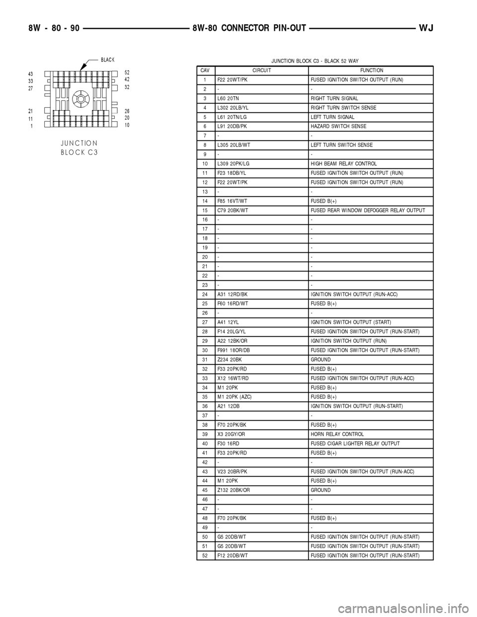
JUNCTION BLOCK C3 - BLACK 52 WAY
CAV CIRCUIT FUNCTION
1 F22 20WT/PK FUSED IGNITION SWITCH OUTPUT (RUN)
2- -
3 L60 20TN RIGHT TURN SIGNAL
4 L302 20LB/YL RIGHT TURN SWITCH SENSE
5 L61 20TN/LG LEFT TURN SIGNAL
6 L91 20DB/PK HAZARD SWITCH SENSE
7- -
8 L305 20LB/WT LEFT TURN SWITCH SENSE
9- -
10 L309 20PK/LG HIGH BEAM RELAY CONTROL
11 F23 18DB/YL FUSED IGNITION SWITCH OUTPUT (RUN)
12 F22 20WT/PK FUSED IGNITION SWITCH OUTPUT (RUN)
13 - -
14 F85 16VT/WT FUSED B(+)
15 C79 20BK/WT FUSED REAR WINDOW DEFOGGER RELAY OUTPUT
16 - -
17 - -
18 - -
19 - -
20 - -
21 - -
22 - -
23 - -
24 A31 12RD/BK IGNITION SWITCH OUTPUT (RUN-ACC)
25 F60 16RD/WT FUSED B(+)
26 - -
27 A41 12YL IGNITION SWITCH OUTPUT (START)
28 F14 20LG/YL FUSED IGNITION SWITCH OUTPUT (RUN-START)
29 A22 12BK/OR IGNITION SWITCH OUTPUT (RUN)
30 F991 18OR/DB FUSED IGNITION SWITCH OUTPUT (RUN-START)
31 Z234 20BK GROUND
32 F33 20PK/RD FUSED B(+)
33 X12 16WT/RD FUSED IGNITION SWITCH OUTPUT (RUN-ACC)
34 M1 20PK FUSED B(+)
35 M1 20PK (AZC) FUSED B(+)
36 A21 12DB IGNITION SWITCH OUTPUT (RUN-START)
37 - -
38 F70 20PK/BK FUSED B(+)
39 X3 20GY/OR HORN RELAY CONTROL
40 F30 16RD FUSED CIGAR LIGHTER RELAY OUTPUT
41 F33 20PK/RD FUSED B(+)
42 - -
43 V23 20BR/PK FUSED IGNITION SWITCH OUTPUT (RUN-ACC)
44 M1 20PK FUSED B(+)
45 Z132 20BK/OR GROUND
46 - -
47 - -
48 F70 20PK/BK FUSED B(+)
49 - -
50 G5 20DB/WT FUSED IGNITION SWITCH OUTPUT (RUN-START)
51 G5 20DB/WT FUSED IGNITION SWITCH OUTPUT (RUN-START)
52 F12 20DB/WT FUSED IGNITION SWITCH OUTPUT (RUN-START)
8W - 80 - 90 8W-80 CONNECTOR PIN-OUTWJ
Page 1142 of 2199
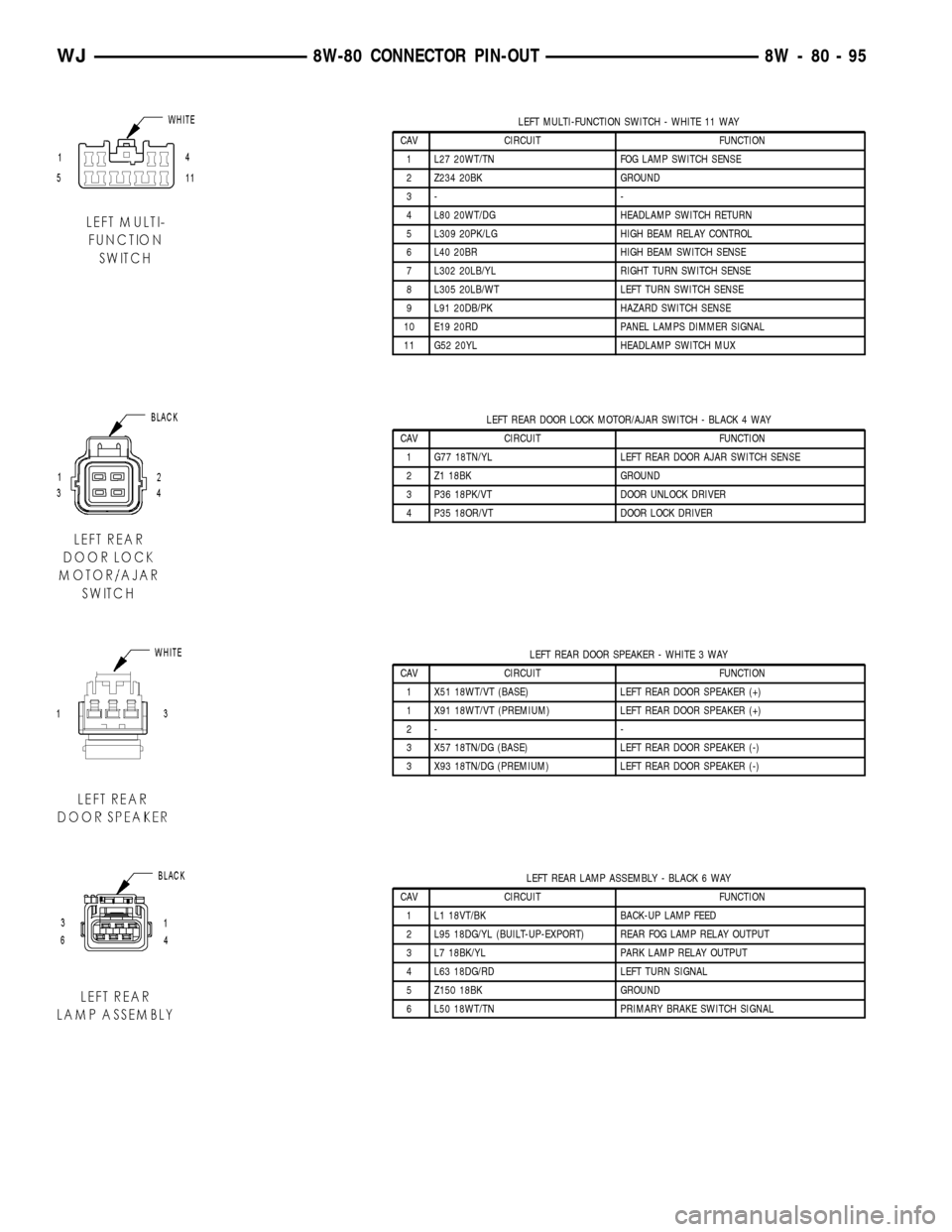
LEFT MULTI-FUNCTION SWITCH - WHITE 11 WAY
CAV CIRCUIT FUNCTION
1 L27 20WT/TN FOG LAMP SWITCH SENSE
2 Z234 20BK GROUND
3- -
4 L80 20WT/DG HEADLAMP SWITCH RETURN
5 L309 20PK/LG HIGH BEAM RELAY CONTROL
6 L40 20BR HIGH BEAM SWITCH SENSE
7 L302 20LB/YL RIGHT TURN SWITCH SENSE
8 L305 20LB/WT LEFT TURN SWITCH SENSE
9 L91 20DB/PK HAZARD SWITCH SENSE
10 E19 20RD PANEL LAMPS DIMMER SIGNAL
11 G52 20YL HEADLAMP SWITCH MUX
LEFT REAR DOOR LOCK MOTOR/AJAR SWITCH - BLACK 4 WAY
CAV CIRCUIT FUNCTION
1 G77 18TN/YL LEFT REAR DOOR AJAR SWITCH SENSE
2 Z1 18BK GROUND
3 P36 18PK/VT DOOR UNLOCK DRIVER
4 P35 18OR/VT DOOR LOCK DRIVER
LEFT REAR DOOR SPEAKER - WHITE 3 WAY
CAV CIRCUIT FUNCTION
1 X51 18WT/VT (BASE) LEFT REAR DOOR SPEAKER (+)
1 X91 18WT/VT (PREMIUM) LEFT REAR DOOR SPEAKER (+)
2- -
3 X57 18TN/DG (BASE) LEFT REAR DOOR SPEAKER (-)
3 X93 18TN/DG (PREMIUM) LEFT REAR DOOR SPEAKER (-)
LEFT REAR LAMP ASSEMBLY - BLACK 6 WAY
CAV CIRCUIT FUNCTION
1 L1 18VT/BK BACK-UP LAMP FEED
2 L95 18DG/YL (BUILT-UP-EXPORT) REAR FOG LAMP RELAY OUTPUT
3 L7 18BK/YL PARK LAMP RELAY OUTPUT
4 L63 18DG/RD LEFT TURN SIGNAL
5 Z150 18BK GROUND
6 L50 18WT/TN PRIMARY BRAKE SWITCH SIGNAL
WJ8W-80 CONNECTOR PIN-OUT 8W - 80 - 95
Page 1143 of 2199
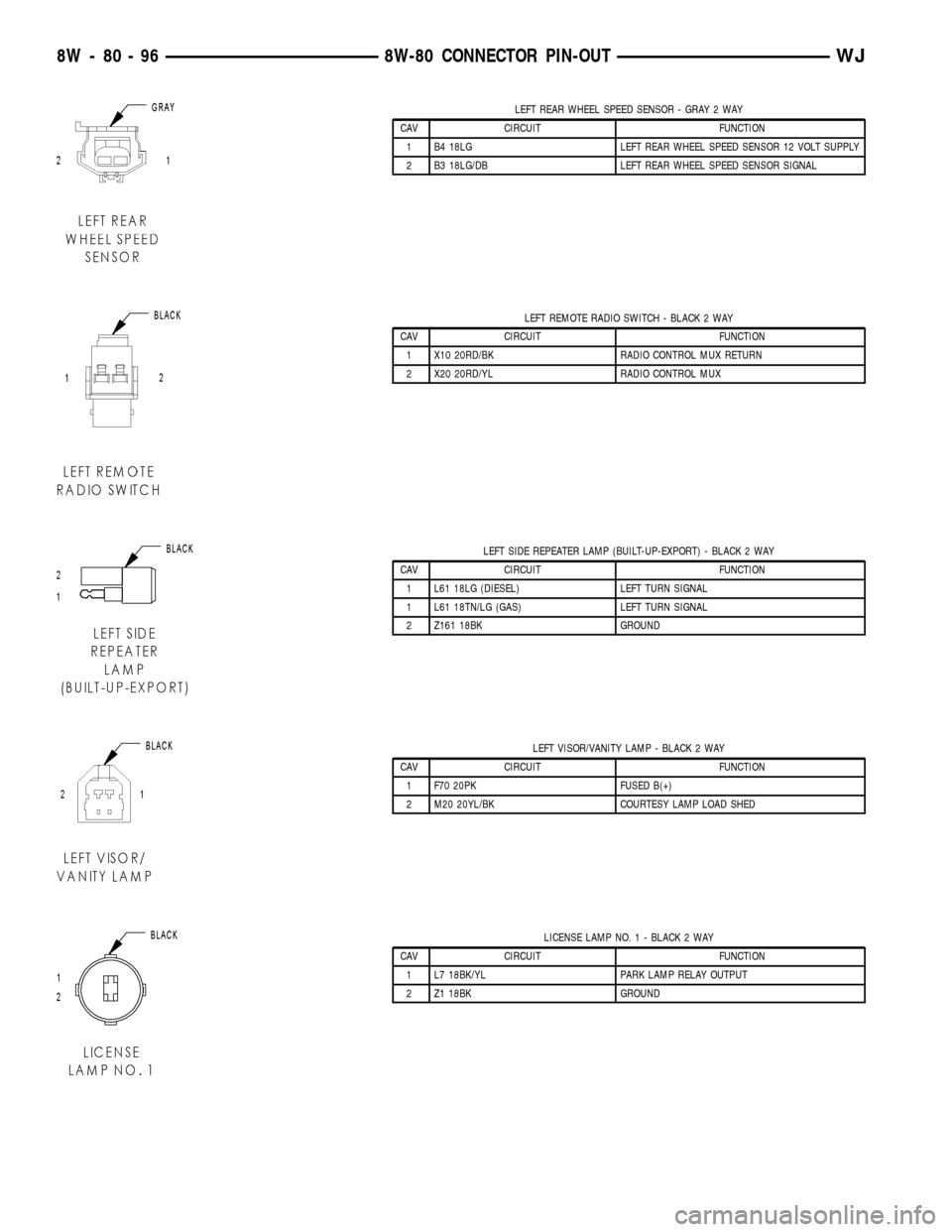
LEFT REAR WHEEL SPEED SENSOR - GRAY 2 WAY
CAV CIRCUIT FUNCTION
1 B4 18LG LEFT REAR WHEEL SPEED SENSOR 12 VOLT SUPPLY
2 B3 18LG/DB LEFT REAR WHEEL SPEED SENSOR SIGNAL
LEFT REMOTE RADIO SWITCH - BLACK 2 WAY
CAV CIRCUIT FUNCTION
1 X10 20RD/BK RADIO CONTROL MUX RETURN
2 X20 20RD/YL RADIO CONTROL MUX
LEFT SIDE REPEATER LAMP (BUILT-UP-EXPORT) - BLACK 2 WAY
CAV CIRCUIT FUNCTION
1 L61 18LG (DIESEL) LEFT TURN SIGNAL
1 L61 18TN/LG (GAS) LEFT TURN SIGNAL
2 Z161 18BK GROUND
LEFT VISOR/VANITY LAMP - BLACK 2 WAY
CAV CIRCUIT FUNCTION
1 F70 20PK FUSED B(+)
2 M20 20YL/BK COURTESY LAMP LOAD SHED
LICENSE LAMP NO. 1 - BLACK 2 WAY
CAV CIRCUIT FUNCTION
1 L7 18BK/YL PARK LAMP RELAY OUTPUT
2 Z1 18BK GROUND
8W - 80 - 96 8W-80 CONNECTOR PIN-OUTWJ
Page 1164 of 2199
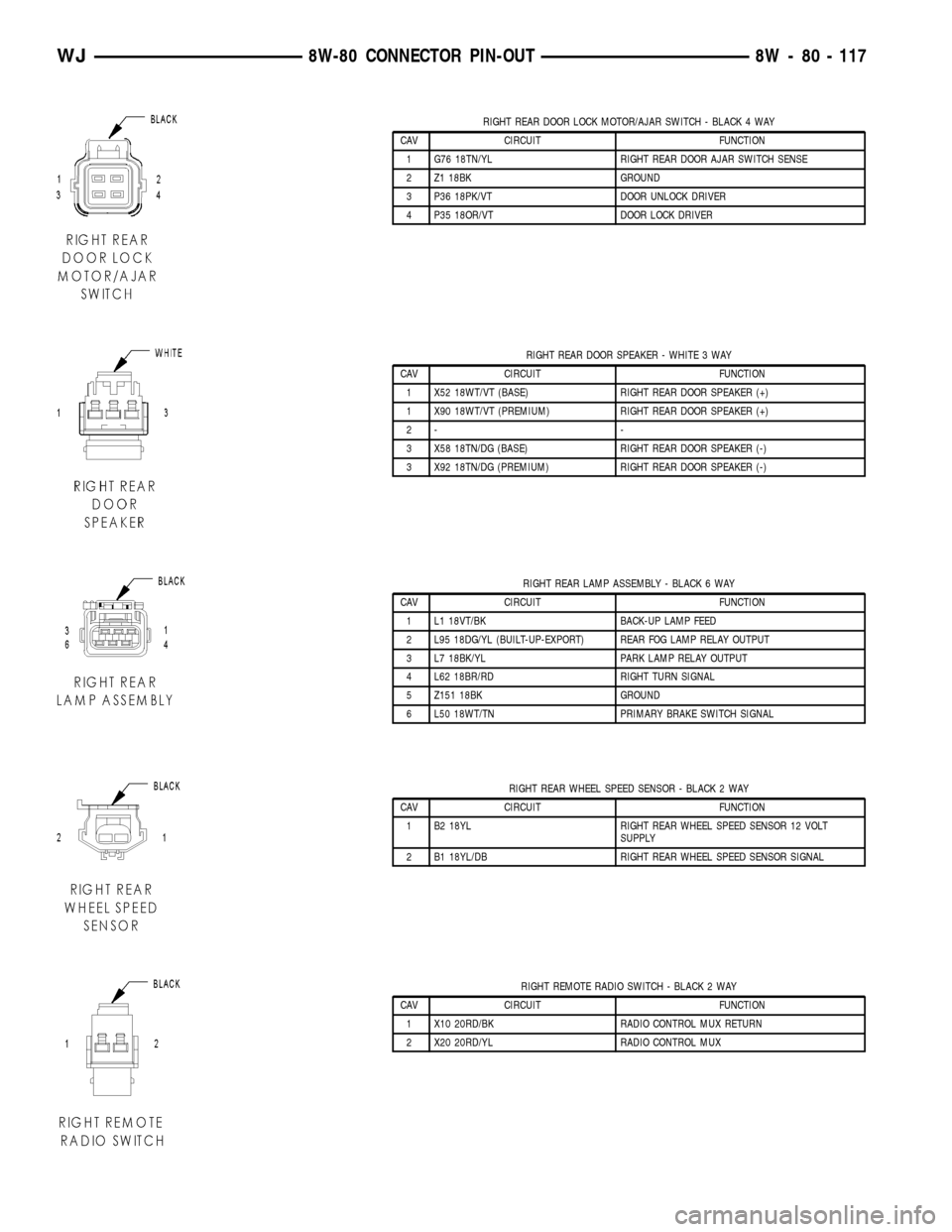
RIGHT REAR DOOR LOCK MOTOR/AJAR SWITCH - BLACK 4 WAY
CAV CIRCUIT FUNCTION
1 G76 18TN/YL RIGHT REAR DOOR AJAR SWITCH SENSE
2 Z1 18BK GROUND
3 P36 18PK/VT DOOR UNLOCK DRIVER
4 P35 18OR/VT DOOR LOCK DRIVER
RIGHT REAR DOOR SPEAKER - WHITE 3 WAY
CAV CIRCUIT FUNCTION
1 X52 18WT/VT (BASE) RIGHT REAR DOOR SPEAKER (+)
1 X90 18WT/VT (PREMIUM) RIGHT REAR DOOR SPEAKER (+)
2- -
3 X58 18TN/DG (BASE) RIGHT REAR DOOR SPEAKER (-)
3 X92 18TN/DG (PREMIUM) RIGHT REAR DOOR SPEAKER (-)
RIGHT REAR LAMP ASSEMBLY - BLACK 6 WAY
CAV CIRCUIT FUNCTION
1 L1 18VT/BK BACK-UP LAMP FEED
2 L95 18DG/YL (BUILT-UP-EXPORT) REAR FOG LAMP RELAY OUTPUT
3 L7 18BK/YL PARK LAMP RELAY OUTPUT
4 L62 18BR/RD RIGHT TURN SIGNAL
5 Z151 18BK GROUND
6 L50 18WT/TN PRIMARY BRAKE SWITCH SIGNAL
RIGHT REAR WHEEL SPEED SENSOR - BLACK 2 WAY
CAV CIRCUIT FUNCTION
1 B2 18YL RIGHT REAR WHEEL SPEED SENSOR 12 VOLT
SUPPLY
2 B1 18YL/DB RIGHT REAR WHEEL SPEED SENSOR SIGNAL
RIGHT REMOTE RADIO SWITCH - BLACK 2 WAY
CAV CIRCUIT FUNCTION
1 X10 20RD/BK RADIO CONTROL MUX RETURN
2 X20 20RD/YL RADIO CONTROL MUX
WJ8W-80 CONNECTOR PIN-OUT 8W - 80 - 117
Page 1165 of 2199
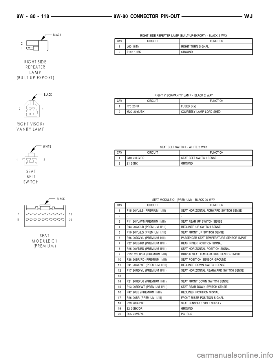
RIGHT SIDE REPEATER LAMP (BUILT-UP-EXPORT) - BLACK 2 WAY
CAV CIRCUIT FUNCTION
1 L60 18TN RIGHT TURN SIGNAL
2 Z142 18BK GROUND
RIGHT VISOR/VANITY LAMP - BLACK 2 WAY
CAV CIRCUIT FUNCTION
1 F70 20PK FUSED B(+)
2 M20 20YL/BK COURTESY LAMP LOAD SHED
SEAT BELT SWITCH - WHITE 2 WAY
CAV CIRCUIT FUNCTION
1 G10 20LG/RD SEAT BELT SWITCH SENSE
2 Z1 20BK GROUND
SEAT MODULE C1 (PREMIUM) - BLACK 20 WAY
CAV CIRCUIT FUNCTION
1 P15 20YL/LB (PREMIUM II/III) SEAT HORIZONTAL FORWARD SWITCH SENSE
2- -
3 P11 20YL/WT(PREMIUM II/III) SEAT REAR UP SWITCH SENSE
4 P43 20GY/LB (PREMIUM II/III) RECLINER UP SWITCH SENSE
5 P19 20YL/LG (PREMIUM II/III) SEAT FRONT UP SWITCH SENSE
6 P86 20DG/YL (PREMIUM I/III) PASSENGER SEAT TEMPERATURE SENSOR INPUT
7 P27 20LB/RD (PREMIUM II/III) REAR RISER POSITION SIGNAL
8 P25 20VT/RD (PREMIUM II/III) SEAT HORIZONTAL POSITION SIGNAL
9 P135 20LB/BK (PREMIUM I/III) DRIVER SEAT TEMPERATURE SENSOR INPUT
10 P28 20BR/RD (PREMIUM II/III) SEAT POSITION SENSOR GROUND
11 P41 20GY/WT (PREMIUM II/III) RECLINER DOWN SWITCH SENSE
12 P17 20RD/YL (PREMIUM II/III) SEAT HORIZONTAL REARWARD SWITCH SENSE
13 - -
14 P21 20RD/LG (PREMIUM II/III) SEAT FRONT DOWN SWITCH SENSE
15 P13 20RD/WT (PREMIUM II/III) SEAT REAR DOWN SWITCH SENSE
16 P47 20LB (PREMIUM II/III) RECLINER POSITION SIGNAL
17 P26 20BR (PREMIUM II/III) FRONT RISER POSITION SIGNAL
18 P29 20BR/WT SEAT SENSOR 5 VOLT SUPPLY
19 Z2 20BK/OR GROUND
20 D25 20VT/YL PCI BUS
8W - 80 - 118 8W-80 CONNECTOR PIN-OUTWJ
Page 1182 of 2199
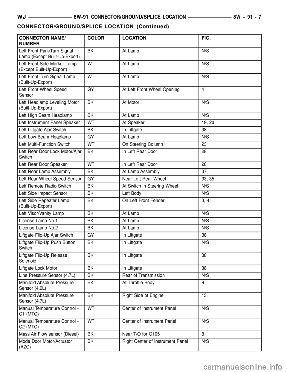
CONNECTOR NAME/
NUMBERCOLOR LOCATION FIG.
Left Front Park/Turn Signal
Lamp (Except Built-Up-Export)BK At Lamp N/S
Left Front Side Marker Lamp
(Except Built-Up-Export)WT At Lamp N/S
Left Front Turn Signal Lamp
(Built-Up-Export)WT At Lamp N/S
Left Front Wheel Speed
SensorGY At Left Front Wheel Opening 4
Left Headlamp Leveling Motor
(Built-Up-Export)BK At Motor N/S
Left High Beam Headlamp BK At Lamp N/S
Left Instrument Panel Speaker WT At Speaker 19, 20
Left Liftgate Ajar Switch BK In Liftgate 38
Left Low Beam Headlamp GY At Lamp N/S
Left Multi-Function Switch WT On Steering Column 23
Left Rear Door Lock Motor/Ajar
SwitchBK In Left Rear Door 28
Left Rear Door Speaker WT In Left Rear Door 28
Left Rear Lamp Assembly BK At Lamp Assembly 37
Left Rear Wheel Speed Sensor GY Near Left Rear Wheel 33, 35
Left Remote Radio Switch BK At Switch in Steering Wheel N/S
Left Side Impact Sensor BK Left Body N/S
Left Side Repeater Lamp
(Built-Up-Export)BK On Left Front Fender 3, 4
Left Visor/Vanity Lamp BK At Lamp N/S
License Lamp No.1 BK At Lamp N/S
License Lamp No.2 BK At Lamp N/S
Liftgate Flip-Up Ajar Switch GY In Liftgate 38
Liftgate Flip-Up Push Button
SwitchBK In Liftgate N/S
Liftgate Flip-Up Release
SolenoidBK In Liftgate 38
Liftgate Lock Motor BK In Liftgate 38
Line Pressure Sensor (4.7L) BK Rear of Transmission N/S
Manifold Absolute Pressure
Sensor (4.0L)BK At Throttle Body 9
Manifold Absolute Pressure
Sensor (4.7L)BK Right Side of Engine 13
Manual Temperature Control -
C1 (MTC)WT Center of Instrument Panel N/S
Manual Temperature Control -
C2 (MTC)WT Center of Instrument Panel N/S
Mass Air Flow sensor (Diesel) BK Near T/O for G105 8
Mode Door Motor/Actuator
(AZC)BK Right Center of Instrument Panel N/S
WJ8W-91 CONNECTOR/GROUND/SPLICE LOCATION 8W - 91 - 7
CONNECTOR/GROUND/SPLICE LOCATION (Continued)
Page 1185 of 2199
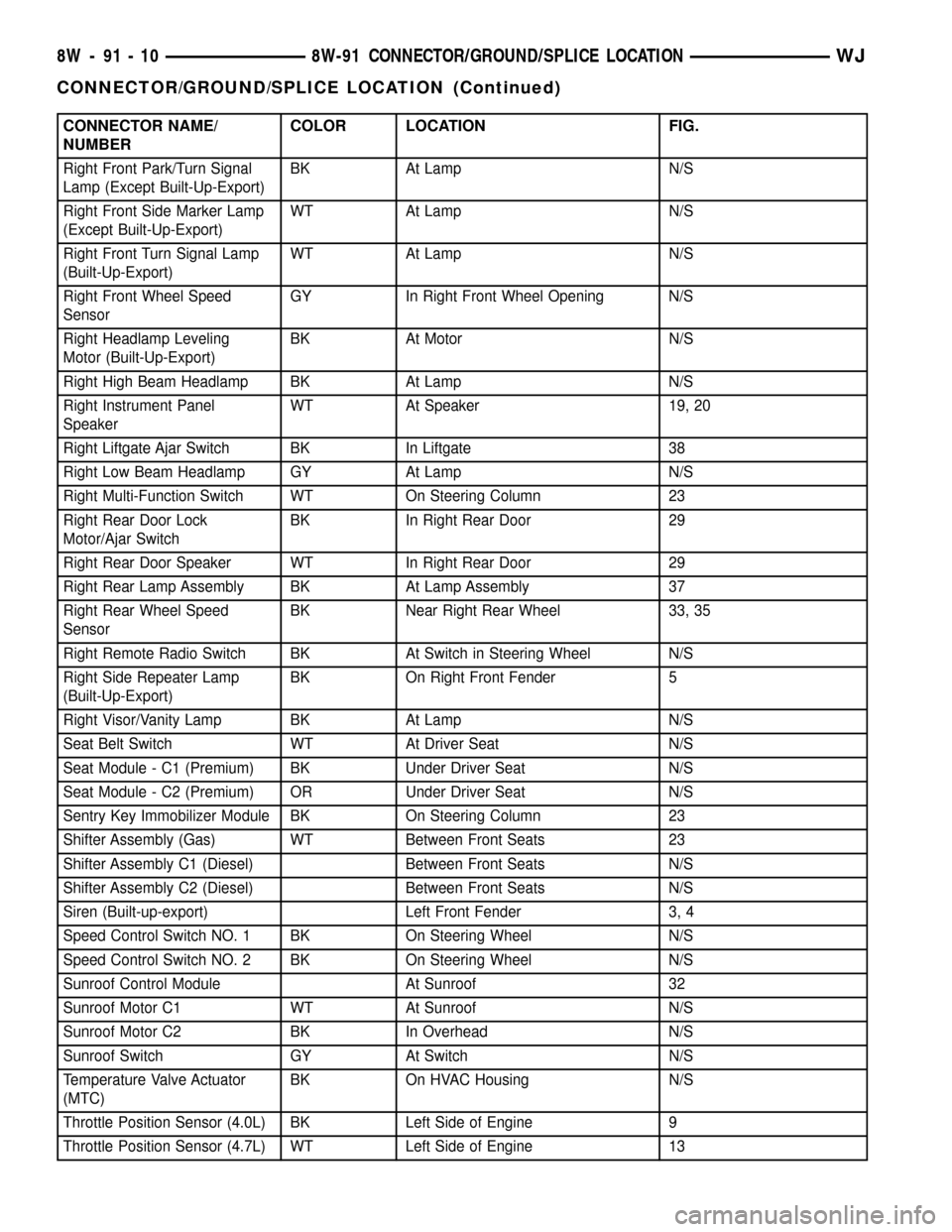
CONNECTOR NAME/
NUMBERCOLOR LOCATION FIG.
Right Front Park/Turn Signal
Lamp (Except Built-Up-Export)BK At Lamp N/S
Right Front Side Marker Lamp
(Except Built-Up-Export)WT At Lamp N/S
Right Front Turn Signal Lamp
(Built-Up-Export)WT At Lamp N/S
Right Front Wheel Speed
SensorGY In Right Front Wheel Opening N/S
Right Headlamp Leveling
Motor (Built-Up-Export)BK At Motor N/S
Right High Beam Headlamp BK At Lamp N/S
Right Instrument Panel
SpeakerWT At Speaker 19, 20
Right Liftgate Ajar Switch BK In Liftgate 38
Right Low Beam Headlamp GY At Lamp N/S
Right Multi-Function Switch WT On Steering Column 23
Right Rear Door Lock
Motor/Ajar SwitchBK In Right Rear Door 29
Right Rear Door Speaker WT In Right Rear Door 29
Right Rear Lamp Assembly BK At Lamp Assembly 37
Right Rear Wheel Speed
SensorBK Near Right Rear Wheel 33, 35
Right Remote Radio Switch BK At Switch in Steering Wheel N/S
Right Side Repeater Lamp
(Built-Up-Export)BK On Right Front Fender 5
Right Visor/Vanity Lamp BK At Lamp N/S
Seat Belt Switch WT At Driver Seat N/S
Seat Module - C1 (Premium) BK Under Driver Seat N/S
Seat Module - C2 (Premium) OR Under Driver Seat N/S
Sentry Key Immobilizer Module BK On Steering Column 23
Shifter Assembly (Gas) WT Between Front Seats 23
Shifter Assembly C1 (Diesel) Between Front Seats N/S
Shifter Assembly C2 (Diesel) Between Front Seats N/S
Siren (Built-up-export) Left Front Fender 3, 4
Speed Control Switch NO. 1 BK On Steering Wheel N/S
Speed Control Switch NO. 2 BK On Steering Wheel N/S
Sunroof Control Module At Sunroof 32
Sunroof Motor C1 WT At Sunroof N/S
Sunroof Motor C2 BK In Overhead N/S
Sunroof Switch GY At Switch N/S
Temperature Valve Actuator
(MTC)BK On HVAC Housing N/S
Throttle Position Sensor (4.0L) BK Left Side of Engine 9
Throttle Position Sensor (4.7L) WT Left Side of Engine 13
8W - 91 - 10 8W-91 CONNECTOR/GROUND/SPLICE LOCATIONWJ
CONNECTOR/GROUND/SPLICE LOCATION (Continued)
Page 1376 of 2199

NOTE: When installing oil pan gasket/windage tray,
start four pan bolts at each corner before tightening
oil pickup tube. This will keep pan gasket in align-
ment.
(3) Install oil pump pick-up tube using a new
O-ring. First tighten bolt at O-ring end of tube to 28
N´m (20 ft. lbs.). Tighten remain tube support fasten-
ers to 28 N´m (20 ft. lbs.).
(4) Install oil pan and tighten fasteners to 15 N´m
(11 ft. lbs.) (Fig. 95).
(5) Reconnect transmission oil cooler lines to oil
pan stud bolt.
(6) Install starter (Refer to 8 - ELECTRICAL/
STARTING/STARTER MOTOR - INSTALLATION).
(7) Install exhaust system Y-pipe.
(8) Install structural cover (Refer to 9 - ENGINE/
ENGINE BLOCK/STRUCTURAL COVER - INSTAL-
LATION).
(9) Lower vehicle.
(10) Fill engine with proper amount of oil (Refer to
LUBRICATION & MAINTENANCE/FLUID TYPES -
SPECIFICATIONS).
(11) Connect negative cable to battery.
OIL PRESSURE SENSOR/
SWITCH
DESCRIPTION
The 3±wire, solid-state engine oil pressure sensor
(sending unit) is located in an engine oil pressure
gallery.
OPERATION
The oil pressure sensor uses three circuits. They are:
²A 5±volt power supply from the Powertrain Con-
trol Module (PCM)
²A sensor ground through the PCM's sensor
return
²
A signal to the PCM relating to engine oil pressure
The oil pressure sensor has a 3±wire electrical
function very much like the Manifold Absolute Pres-
sure (MAP) sensor. Meaning different pressures
relate to different output voltages.
A 5±volt supply is sent to the sensor from the PCM
to power up the sensor. The sensor returns a voltage
signal back to the PCM relating to engine oil pres-
sure. This signal is then transferred (bussed) to the
instrument panel on either a CCD or PCI bus circuit
(depending on vehicle line) to operate the oil pressure
gauge and the check gauges lamp. Ground for the
sensor is provided by the PCM through a low-noise
sensor return.
REMOVAL
(1) Disconnect the negative cable from the battery.
(2) Raise vehicle on hoist.
(3) Remove front splash shield.
(4) Disconnect oil pressure sender wire (Fig. 96).
(5) Remove the pressure sender (Fig. 96).
INSTALLATION
(1) Install oil pressure sender.
(2) Connect oil pressure sender wire.
(3) Install front splash shield.
(4) Lower vehicle.
(5) Connect the negative battery cable.
Fig. 95 Oil Pan Tightening Sequence
Fig. 96 Oil Pressure Sending Unit
1 - BELT
2 - OIL PRESSURE SENSOR
3 - OIL FILTER
4 - ELEC. CONNECTOR
WJENGINE - 4.7L 9 - 133
OIL PAN (Continued)
Page 1605 of 2199

OVERDRIVE CLUTCH
DESCRIPTION
The overdrive clutch (Fig. 125) is composed of the
pressure plate, clutch plates, holding discs, overdrive
piston retainer, piston, piston spacer, and snap-rings.
The overdrive clutch is the forwardmost component
in the transmission overdrive unit and is considered
a holding component. The overdrive piston retainer,
piston, and piston spacer are located on the rear of
the main transmission case.
NOTE: The number of discs and plates may vary
with each engine and vehicle combination.
OPERATION
To apply the clutch, pressure is applied between
the piston retainer and piston. The fluid pressure is
provided by the oil pump, transferred through the
control valves and passageways, and enters the
clutch through passages at the lower rear portion of
the valve body area. With pressure applied between
the piston retainer and piston, the piston moves
away from the piston retainer and compresses the
clutch pack. This action applies the clutch pack,
allowing torque to flow through the intermediate
shaft into the overdrive planetary gear set. The over-
drive clutch discs are attached to the overdrive clutch
hub while the overdrive clutch plates, reaction plate,
and pressure plate are lugged to the overdrive hous-
ing. This allows the intermediate shaft to transferthe engine torque to the planetary gear and overrun-
ning clutch. This drives the planetary gear inside the
annulus, which is attached to the overdrive clutch
drum and output shaft, creating the desired gear
ratio. The waved snap-ring is used to cushion the
application of the clutch pack.
OVERDRIVE OFF SWITCH
DESCRIPTION
The overdrive OFF (control) switch is located in
the shifter handle. The switch is a momentary con-
tact device that signals the PCM to toggle current
status of the overdrive function.
OPERATION
At key-on, fourth gear operation is allowed. Press-
ing the switch once causes the overdrive OFF mode
to be entered and the overdrive OFF switch lamp to
be illuminated. Pressing the switch a second time
causes normal overdrive operation to be restored and
the overdrive lamp to be turned off. The overdrive
OFF mode defaults to ON after the ignition switch is
cycled OFF and ON. The normal position for the con-
trol switch is the ON position. The switch must be in
this position to energize the solenoid and allow
upshifts to fourth gear. The control switch indicator
light illuminates only when the overdrive switch is
turned to the OFF position, or when illuminated by
the powertrain control module.
Fig. 125 Overdrive Clutch
1 - REACTION PLATE 2 - PRESSURE PLATE
21 - 86 AUTOMATIC TRANSMISSION - 42REWJ
Page 1773 of 2199

OUTPUT SPEED SENSOR
DESCRIPTION
The Input and Output Speed Sensors are two-wire
magnetic pickup devices that generate AC signals as
rotation occurs. They are mounted in the left side of
the transmission case and are considered primary
inputs to the Transmission Control Module (TCM).
OPERATION
The Input Speed Sensor provides information on
how fast the input shaft is rotating. As the teeth of
the input clutch hub pass by the sensor coil, an AC
voltage is generated and sent to the TCM. The TCM
interprets this information as input shaft rpm.
The Output Speed Sensor generates an AC signal
in a similar fashion, though its coil is excited by rota-
tion of the rear planetary carrier lugs. The TCM
interprets this information as output shaft rpm.
The TCM compares the input and output speed
signals to determine the following:
²Transmission gear ratio
²Speed ratio error detection
²CVI calculation
The TCM also compares the input speed signal and
the engine speed signal to determine the following:
²Torque converter clutch slippage
²Torque converter element speed ratio
REMOVAL
(1) Raise vehicle.
(2) Place a suitable fluid catch pan under the
transmission.
(3) Remove the wiring connector from the output
speed sensor (Fig. 96).
(4) Remove the bolt holding the output speed sen-
sor to the transmission case.
(5) Remove the output speed sensor from the
transmission case.
INSTALLATION
(1) Install the output speed sensor into the trans-
mission case.
(2) Install the bolt to hold the output speed sensor
into the transmission case. Tighten the bolt to 11.9
N´m (105 in.lbs.).
(3) Install the wiring connector onto the output
speed sensor
(4) Verify the transmission fluid level. Add fluid as
necessary.
(5) Lower vehicle.
OVERDRIVE SWITCH
DESCRIPTION
The overdrive OFF (control) switch is located in
the shifter handle. The switch is a momentary con-
tact device that signals the PCM to toggle current
status of the overdrive function.
OPERATION
At key-on, fourth and fifth gear operation is
allowed. Pressing the switch once causes the over-
drive OFF mode to be entered and the overdrive OFF
switch lamp to be illuminated. Pressing the switch a
second time causes normal overdrive operation to be
restored and the overdrive lamp to be turned off. The
overdrive OFF mode defaults to ON after the ignition
switch is cycled OFF and ON. The normal position
for the control switch is the ON position. The switch
must be in this position to energize the solenoids and
allow upshifts to fourth and fifth gears. The control
switch indicator light illuminates only when the over-
drive switch is turned to the OFF position, or when
illuminated by the transmission control module.
Fig. 96 Output Speed Sensor
1 - OUTPUT SPEED SENSOR
2 - LINE PRESSURE SENSOR
3 - INPUT SPEED SENSOR
21 - 254 AUTOMATIC TRANSMISSION - 545RFEWJ