4.0 automatic trans JEEP GRAND CHEROKEE 2002 WJ / 2.G Workshop Manual
[x] Cancel search | Manufacturer: JEEP, Model Year: 2002, Model line: GRAND CHEROKEE, Model: JEEP GRAND CHEROKEE 2002 WJ / 2.GPages: 2199, PDF Size: 76.01 MB
Page 12 of 2199
LUBRICATION & MAINTENANCE
TABLE OF CONTENTS
page page
LUBRICATION & MAINTENANCE
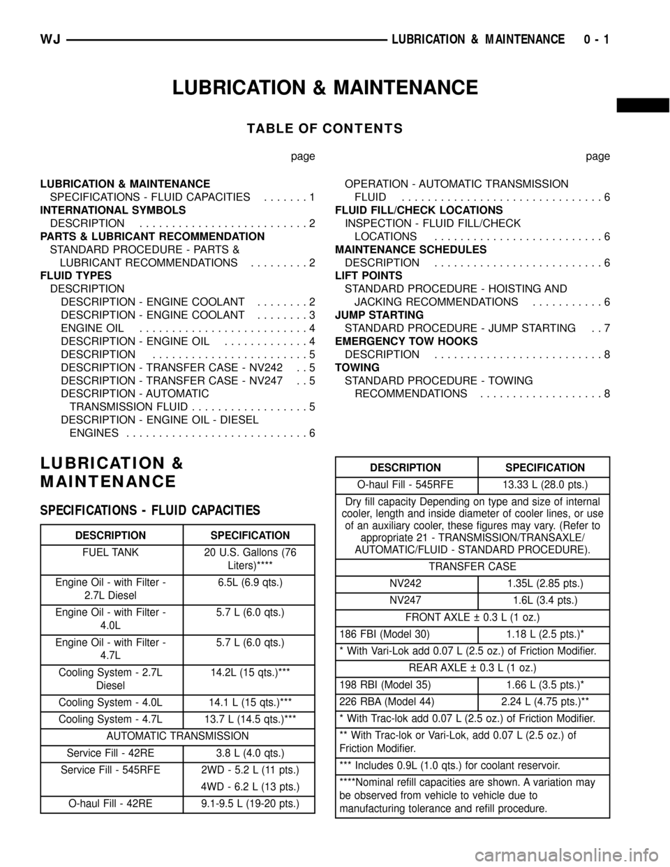
SPECIFICATIONS - FLUID CAPACITIES.......1
INTERNATIONAL SYMBOLS
DESCRIPTION..........................2
PARTS & LUBRICANT RECOMMENDATION
STANDARD PROCEDURE - PARTS &
LUBRICANT RECOMMENDATIONS.........2
FLUID TYPES
DESCRIPTION
DESCRIPTION - ENGINE COOLANT........2
DESCRIPTION - ENGINE COOLANT........3
ENGINE OIL..........................4
DESCRIPTION - ENGINE OIL.............4
DESCRIPTION........................5
DESCRIPTION - TRANSFER CASE - NV242 . . 5
DESCRIPTION - TRANSFER CASE - NV247 . . 5
DESCRIPTION - AUTOMATIC
TRANSMISSION FLUID..................5
DESCRIPTION - ENGINE OIL - DIESEL
ENGINES............................6OPERATION - AUTOMATIC TRANSMISSION
FLUID...............................6
FLUID FILL/CHECK LOCATIONS
INSPECTION - FLUID FILL/CHECK
LOCATIONS..........................6
MAINTENANCE SCHEDULES
DESCRIPTION..........................6
LIFT POINTS
STANDARD PROCEDURE - HOISTING AND
JACKING RECOMMENDATIONS...........6
JUMP STARTING
STANDARD PROCEDURE - JUMP STARTING . . 7
EMERGENCY TOW HOOKS
DESCRIPTION..........................8
TOWING
STANDARD PROCEDURE - TOWING
RECOMMENDATIONS...................8
LUBRICATION &
MAINTENANCE
SPECIFICATIONS - FLUID CAPACITIES
DESCRIPTION SPECIFICATION
FUEL TANK 20 U.S. Gallons (76
Liters)****
Engine Oil - with Filter -
2.7L Diesel6.5L (6.9 qts.)
Engine Oil - with Filter -
4.0L5.7 L (6.0 qts.)
Engine Oil - with Filter -
4.7L5.7 L (6.0 qts.)
Cooling System - 2.7L
Diesel14.2L (15 qts.)***
Cooling System - 4.0L 14.1 L (15 qts.)***
Cooling System - 4.7L 13.7 L (14.5 qts.)***
AUTOMATIC TRANSMISSION
Service Fill - 42RE 3.8 L (4.0 qts.)
Service Fill - 545RFE 2WD - 5.2 L (11 pts.)
4WD - 6.2 L (13 pts.)
O-haul Fill - 42RE 9.1-9.5 L (19-20 pts.)
DESCRIPTION SPECIFICATION
O-haul Fill - 545RFE 13.33 L (28.0 pts.)
Dry fill capacity Depending on type and size of internal
cooler, length and inside diameter of cooler lines, or use
of an auxiliary cooler, these figures may vary. (Refer to
appropriate 21 - TRANSMISSION/TRANSAXLE/
AUTOMATIC/FLUID - STANDARD PROCEDURE).
TRANSFER CASE
NV242 1.35L (2.85 pts.)
NV247 1.6L (3.4 pts.)
FRONT AXLE 0.3 L (1 oz.)
186 FBI (Model 30) 1.18 L (2.5 pts.)*
* With Vari-Lok add 0.07 L (2.5 oz.) of Friction Modifier.
REAR AXLE 0.3 L (1 oz.)
198 RBI (Model 35) 1.66 L (3.5 pts.)*
226 RBA (Model 44) 2.24 L (4.75 pts.)**
* With Trac-lok add 0.07 L (2.5 oz.) of Friction Modifier.
** With Trac-lok or Vari-Lok, add 0.07 L (2.5 oz.) of
Friction Modifier.
*** Includes 0.9L (1.0 qts.) for coolant reservoir.
****Nominal refill capacities are shown. A variation may
be observed from vehicle to vehicle due to
manufacturing tolerance and refill procedure.
WJLUBRICATION & MAINTENANCE 0 - 1
Page 16 of 2199
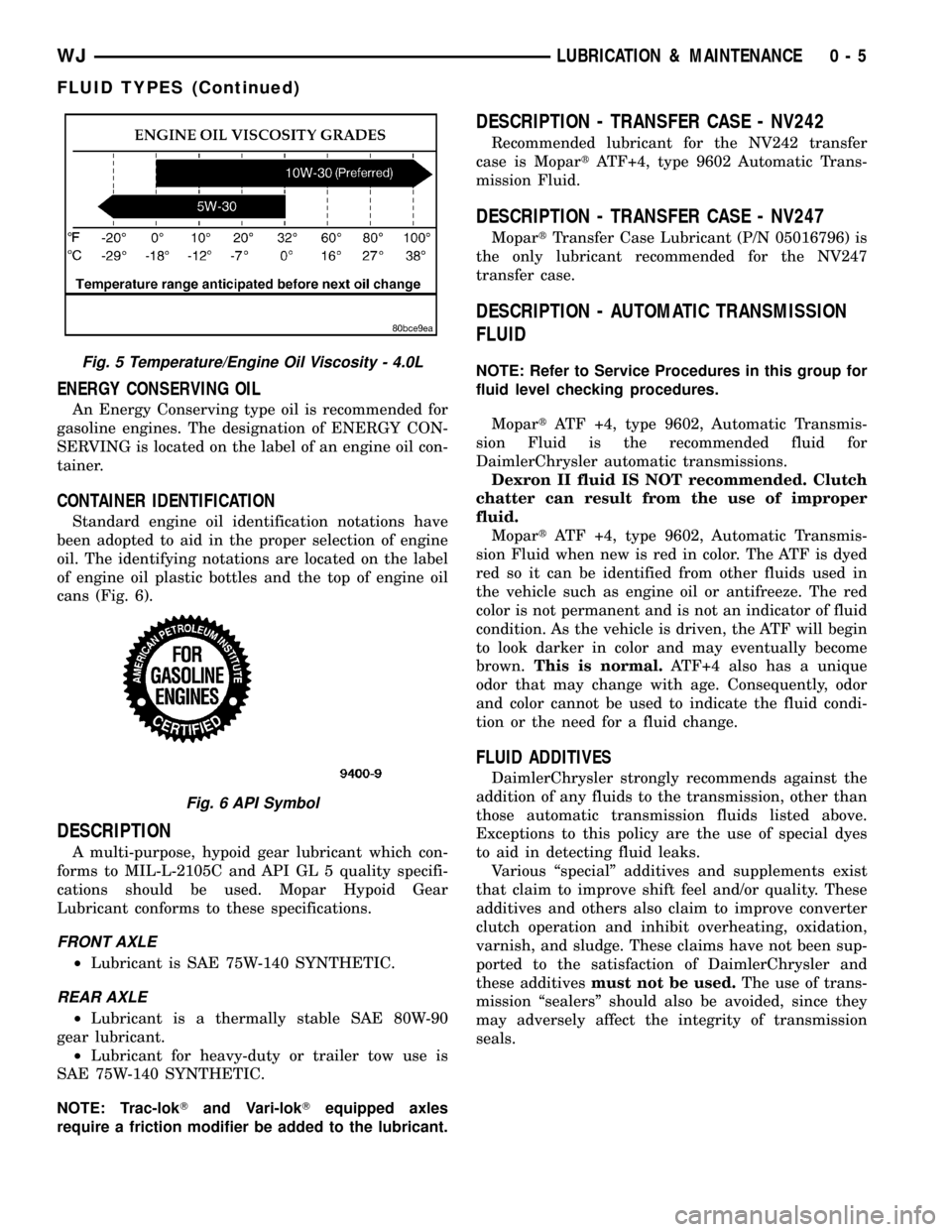
ENERGY CONSERVING OIL
An Energy Conserving type oil is recommended for
gasoline engines. The designation of ENERGY CON-
SERVING is located on the label of an engine oil con-
tainer.
CONTAINER IDENTIFICATION
Standard engine oil identification notations have
been adopted to aid in the proper selection of engine
oil. The identifying notations are located on the label
of engine oil plastic bottles and the top of engine oil
cans (Fig. 6).
DESCRIPTION
A multi-purpose, hypoid gear lubricant which con-
forms to MIL-L-2105C and API GL 5 quality specifi-
cations should be used. Mopar Hypoid Gear
Lubricant conforms to these specifications.
FRONT AXLE
²Lubricant is SAE 75W-140 SYNTHETIC.
REAR AXLE
²Lubricant is a thermally stable SAE 80W-90
gear lubricant.
²Lubricant for heavy-duty or trailer tow use is
SAE 75W-140 SYNTHETIC.
NOTE: Trac-lokTand Vari-lokTequipped axles
require a friction modifier be added to the lubricant.
DESCRIPTION - TRANSFER CASE - NV242
Recommended lubricant for the NV242 transfer
case is MopartATF+4, type 9602 Automatic Trans-
mission Fluid.
DESCRIPTION - TRANSFER CASE - NV247
MopartTransfer Case Lubricant (P/N 05016796) is
the only lubricant recommended for the NV247
transfer case.
DESCRIPTION - AUTOMATIC TRANSMISSION
FLUID
NOTE: Refer to Service Procedures in this group for
fluid level checking procedures.
MopartATF +4, type 9602, Automatic Transmis-
sion Fluid is the recommended fluid for
DaimlerChrysler automatic transmissions.
Dexron II fluid IS NOT recommended. Clutch
chatter can result from the use of improper
fluid.
MopartATF +4, type 9602, Automatic Transmis-
sion Fluid when new is red in color. The ATF is dyed
red so it can be identified from other fluids used in
the vehicle such as engine oil or antifreeze. The red
color is not permanent and is not an indicator of fluid
condition. As the vehicle is driven, the ATF will begin
to look darker in color and may eventually become
brown.This is normal.ATF+4 also has a unique
odor that may change with age. Consequently, odor
and color cannot be used to indicate the fluid condi-
tion or the need for a fluid change.
FLUID ADDITIVES
DaimlerChrysler strongly recommends against the
addition of any fluids to the transmission, other than
those automatic transmission fluids listed above.
Exceptions to this policy are the use of special dyes
to aid in detecting fluid leaks.
Various ªspecialº additives and supplements exist
that claim to improve shift feel and/or quality. These
additives and others also claim to improve converter
clutch operation and inhibit overheating, oxidation,
varnish, and sludge. These claims have not been sup-
ported to the satisfaction of DaimlerChrysler and
these additivesmust not be used.The use of trans-
mission ªsealersº should also be avoided, since they
may adversely affect the integrity of transmission
seals.
Fig. 5 Temperature/Engine Oil Viscosity - 4.0L
Fig. 6 API Symbol
WJLUBRICATION & MAINTENANCE 0 - 5
FLUID TYPES (Continued)
Page 224 of 2199
COOLING
TABLE OF CONTENTS
page page
COOLING
DESCRIPTION
DESCRIPTION - COOLING SYSTEM 4.7L
ENGINE..............................1
DESCRIPTION - COOLING SYSTEM
ROUTING 4.7L ENGINE..................1
DESCRIPTIONÐCOOLING SYSTEM 4.0L
ENGINE..............................1
DESCRIPTIONÐCOOLING SYSTEM
ROUTING 4.0L ENGINE..................1
DESCRIPTIONÐHOSE CLAMPS...........1
OPERATION
OPERATIONÐCOOLING SYSTEM.........2
OPERATIONÐHOSE CLAMPS............2
DIAGNOSIS AND TESTING
DIAGNOSIS AND TESTINGÐON-BOARD
DIAGNOSTICS (OBD)...................3
DIAGNOSIS AND TESTINGÐPRELIMINARY
CHECKS.............................3
DIAGNOSIS AND TESTING - COOLING
SYSTEM DIAGNOSIS CHART.............5
DIAGNOSIS AND TESTING - COOLING
SYSTEM LEAKS......................10DIAGNOSIS AND TESTING - COOLING
SYSTEM DEAERATION.................12
STANDARD PROCEDURE
STANDARD PROCEDUREÐDRAINING
COOLING SYSTEM 4.7L ENGINE.........12
STANDARD PROCEDURE - REFILLING
COOLING SYSTEM 4.7L ENGINE.........12
STANDARD PROCEDURE - DRAINING
COOLING SYSTEM - 4.0L ENGINE........13
STANDARD PROCEDURE - REFILLING
COOLING SYSTEM - 4.0L ENGINE........13
STANDARD PROCEDURE - ADDING
ADDITIONAL COOLANT.................13
STANDARD PROCEDURE - COOLING
SYSTEM - REVERSE FLUSHING..........14
SPECIFICATIONS
TORQUE............................14
SPECIAL TOOLS
COOLING...........................15
ACCESSORY DRIVE......................16
ENGINE...............................24
TRANSMISSION.........................55
COOLING
DESCRIPTION
DESCRIPTION - COOLING SYSTEM 4.7L
ENGINE
The cooling system consists of the following items:
²Hydraulic cooling fan and fan drive assembly
²Radiator
²Power steering oil cooler
²Radiator pressure cap
²Thermostat
²Coolant reserve/overflow system
²Transmission oil cooler (if equipped with an
automatic transmission)
²Coolant
²Water pump
²Hoses and hose clamps
DESCRIPTION - COOLING SYSTEM ROUTING
4.7L ENGINE
For cooling system routing refer to (Fig. 1).
DESCRIPTIONÐCOOLING SYSTEM 4.0L
ENGINE
The cooling system consists of:
²A radiator
²Mechanical Cooling Fan
²Thermal viscous fan drive-Low disengaged
²Fan shroud (Fig. 2)
²Radiator pressure cap
²Thermostat
²Coolant reserve/overflow system
²Transmission oil cooler (if equipped with an
automatic transmission)
²Coolant
²Water pump
²Hoses and hose clamps
²Accessory drive belt
DESCRIPTIONÐCOOLING SYSTEM ROUTING
4.0L ENGINE
For cooling system routing refer to (Fig. 3).
DESCRIPTIONÐHOSE CLAMPS
The cooling system utilizes both worm drive and
spring type hose clamps. If a spring type clamp
WJCOOLING 7 - 1
Page 269 of 2199
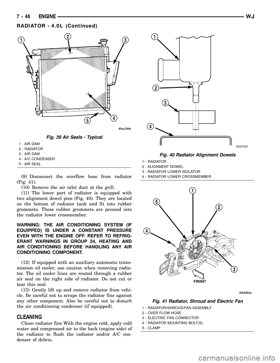
(9) Disconnect the overflow hose from radiator
(Fig. 41).
(10) Remove the air inlet duct at the grill.
(11) The lower part of radiator is equipped with
two alignment dowel pins (Fig. 40). They are located
on the bottom of radiator tank and fit into rubber
grommets. These rubber grommets are pressed into
the radiator lower crossmember.
WARNING: THE AIR CONDITIONING SYSTEM (IF
EQUIPPED) IS UNDER A CONSTANT PRESSURE
EVEN WITH THE ENGINE OFF. REFER TO REFRIG-
ERANT WARNINGS IN GROUP 24, HEATING AND
AIR CONDITIONING BEFORE HANDLING ANY AIR
CONDITIONING COMPONENT.
(12) If equipped with an auxiliary automatic trans-
mission oil cooler, use caution when removing radia-
tor. The oil cooler lines are routed through a rubber
air seal on the right side of radiator. Do not cut or
tear this seal.
(13) Gently lift up and remove radiator from vehi-
cle. Be careful not to scrape the radiator fins against
any other component. Also be careful not to disturb
the air conditioning condenser (if equipped).
CLEANING
Clean radiator fins With the engine cold, apply cold
water and compressed air to the back (engine side) of
the radiator to flush the radiator and/or A/C con-
denser of debris.
Fig. 39 Air Seals - Typical
1 - AIR DAM
2 - RADIATOR
3 - AIR DAM
4 - A/C CONDENSER
5 - AIR SEAL
Fig. 40 Radiator Alignment Dowels
1 - RADIATOR
2 - ALIGNMENT DOWEL
3 - RADIATOR LOWER ISOLATOR
4 - RADIATOR LOWER CROSSMEMBER
Fig. 41 Radiator, Shroud and Electric Fan
1 - RADIATOR/SHROUD/FAN ASSEMBLY
2 - OVER FLOW HOSE
3 - ELECTRIC FAN CONNECTOR
4 - RADIATOR MOUNTING BOLT(S)
5 - CLAMP
7 - 46 ENGINEWJ
RADIATOR - 4.0L (Continued)
Page 366 of 2199
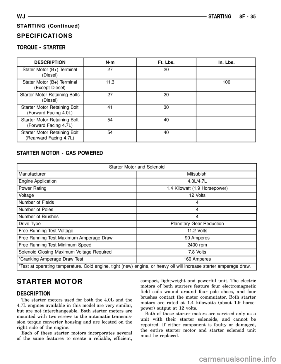
SPECIFICATIONS
TORQUE - STARTER
DESCRIPTION N-m Ft. Lbs. In. Lbs.
Stater Motor (B+) Terminal
(Diesel)27 20
Stater Motor (B+) Terminal
(Except Diesel)11.3 100
Starter Motor Retaining Bolts
(Diesel)27 20
Starter Motor Retaining Bolt
(Forward Facing 4.0L)41 30
Starter Motor Retaining Bolt
(Forward Facing 4.7L)54 40
Starter Motor Retaining Bolt
(Rearward Facing 4.7L)54 40
STARTER MOTOR - GAS POWERED
Starter Motor and Solenoid
Manufacturer Mitsubishi
Engine Application 4.0L/4.7L
Power Rating 1.4 Kilowatt (1.9 Horsepower)
Voltage12 Volts
Number of Fields 4
Number of Poles 4
Number of Brushes 4
Drive Type Planetary Gear Reduction
Free Running Test Voltage 11.2 Volts
Free Running Test Maximum Amperage Draw 90 Amperes
Free Running Test Minimum Speed 2400 rpm
Solenoid Closing Maximum Voltage Required 7.8 Volts
*Cranking Amperage Draw Test 160 Amperes
*Test at operating temperature. Cold engine, tight (new) engine, or heavy oil will increase starter amperage draw.
STARTER MOTOR
DESCRIPTION
The starter motors used for both the 4.0L and the
4.7L engines available in this model are very similar,
but are not interchangeable. Both starter motors are
mounted with two screws to the automatic transmis-
sion torque converter housing and are located on the
right side of the engine.
Each of these starter motors incorporates several
of the same features to create a reliable, efficient,compact, lightweight and powerful unit. The electric
motors of both starters feature four electromagnetic
field coils wound around four pole shoes, and four
brushes contact the motor commutator. Both starter
motors are rated at 1.4 kilowatts (about 1.9 horse-
power) output at 12 volts.
Both of these starter motors are serviced only as a
unit with their starter solenoids, and cannot be
repaired. If either component is faulty or damaged,
the entire starter motor and starter solenoid unit
must be replaced.
WJSTARTING 8F - 35
STARTING (Continued)
Page 368 of 2199
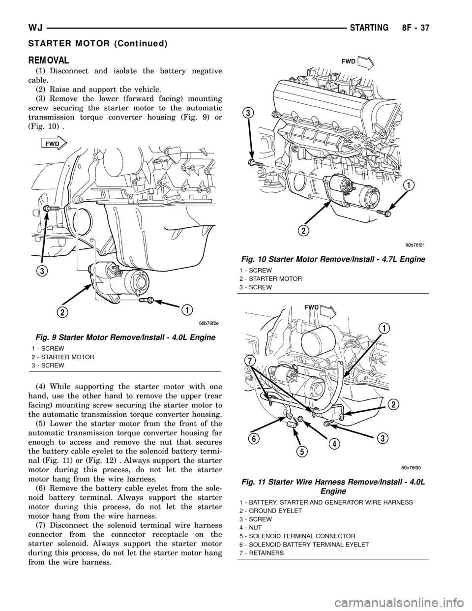
REMOVAL
(1) Disconnect and isolate the battery negative
cable.
(2) Raise and support the vehicle.
(3) Remove the lower (forward facing) mounting
screw securing the starter motor to the automatic
transmission torque converter housing (Fig. 9) or
(Fig. 10) .
(4) While supporting the starter motor with one
hand, use the other hand to remove the upper (rear
facing) mounting screw securing the starter motor to
the automatic transmission torque converter housing.
(5) Lower the starter motor from the front of the
automatic transmission torque converter housing far
enough to access and remove the nut that secures
the battery cable eyelet to the solenoid battery termi-
nal (Fig. 11) or (Fig. 12) . Always support the starter
motor during this process, do not let the starter
motor hang from the wire harness.
(6) Remove the battery cable eyelet from the sole-
noid battery terminal. Always support the starter
motor during this process, do not let the starter
motor hang from the wire harness.
(7) Disconnect the solenoid terminal wire harness
connector from the connector receptacle on the
starter solenoid. Always support the starter motor
during this process, do not let the starter motor hang
from the wire harness.
Fig. 9 Starter Motor Remove/Install - 4.0L Engine
1 - SCREW
2 - STARTER MOTOR
3 - SCREW
Fig. 10 Starter Motor Remove/Install - 4.7L Engine
1 - SCREW
2 - STARTER MOTOR
3 - SCREW
Fig. 11 Starter Wire Harness Remove/Install - 4.0L
Engine
1 - BATTERY, STARTER AND GENERATOR WIRE HARNESS
2 - GROUND EYELET
3 - SCREW
4 - NUT
5 - SOLENOID TERMINAL CONNECTOR
6 - SOLENOID BATTERY TERMINAL EYELET
7 - RETAINERS
WJSTARTING 8F - 37
STARTER MOTOR (Continued)
Page 369 of 2199
(8) Remove the starter motor from the engine com-
partment.
INSTALLATION
(1) Position the starter motor in the engine com-
partment.
(2) Reconnect the solenoid terminal wire harness
connector to the connector receptacle on the starter
solenoid. Always support the starter motor during
this process, do not let the starter motor hang from
the wire harness.
(3) Install the battery cable eyelet onto the sole-
noid battery terminal. Always support the starter
motor during this process, do not let the starter
motor hang from the wire harness.
(4) Install and tighten the nut that secures the
battery cable eyelet to the solenoid battery terminal.
Tighten the nut to 11.3 N´m (100 in. lbs.). Always
support the starter motor during this process, do not
let the starter motor hang from the wire harness.
(5) Position the starter motor to the front of the
automatic transmission torque converter housing and
loosely install both the upper and lower mounting
screws.
(6) Tighten the lower (forward facing) starter
motor mounting screw. On 4.0L engines, tighten the
screw to 41 N´m (30 ft. lbs.). On 4.7L engines, tighten
the screw to 54 N´m (40 ft. lbs.).(7) Tighten the upper (rearward facing) starter
mounting screw. Tighten the screw to 54 N´m (40 ft.
lbs.).
(8) Lower the vehicle.
(9) Reconnect the battery negative cable.
STARTER MOTOR RELAY
DESCRIPTION
The starter relay is an electromechanical device
that switches battery current to the pull-in coil of the
starter solenoid when the ignition switch is turned to
the Start position. The starter relay is located in the
Power Distribution Center (PDC), in the engine com-
partment. See the fuse and relay layout label affixed
to the inside surface of the PDC cover for starter
relay identification and location.
The starter relay is a International Standards
Organization (ISO) micro-relay. Relays conforming to
the ISO specifications have common physical dimen-
sions, current capacities, terminal patterns, and ter-
minal functions. The ISO micro-relay terminal
functions are the same as a conventional ISO relay.
However, the ISO micro-relay terminal pattern (or
footprint) is different, the current capacity is lower,
and the physical dimensions are smaller than those
of the conventional ISO relay.
The starter relay cannot be repaired or adjusted
and, if faulty or damaged, it must be replaced.
OPERATION
The ISO relay consists of an electromagnetic coil, a
resistor or diode, and three (two fixed and one mov-
able) electrical contacts. The movable (common feed)
relay contact is held against one of the fixed contacts
(normally closed) by spring pressure. When the elec-
tromagnetic coil is energized, it draws the movable
contact away from the normally closed fixed contact,
and holds it against the other (normally open) fixed
contact.
When the electromagnetic coil is de-energized,
spring pressure returns the movable contact to the
normally closed position. The resistor or diode is con-
nected in parallel with the electromagnetic coil in the
relay, and helps to dissipate voltage spikes that are
produced when the coil is de-energized.
DIAGNOSIS AND TESTING - STARTER RELAY
The starter relay (Fig. 13) is located in the Power
Distribution Center (PDC), in the engine compart-
ment. Refer to the fuse and relay layout label affixed
to the underside of the PDC cover for starter relay
identification and location. For complete circuit dia-
grams, refer toStarting Systemin the Contents of
Group 8W - Wiring Diagrams.
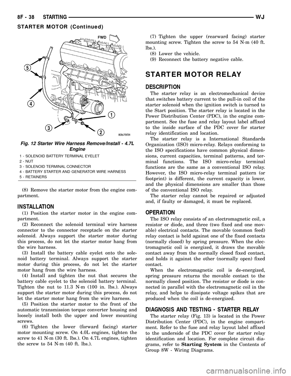
Fig. 12 Starter Wire Harness Remove/Install - 4.7L
Engine
1 - SOLENOID BATTERY TERMINAL EYELET
2 - NUT
3 - SOLENOID TERMINAL CONNECTOR
4 - BATTERY STARTER AND GENERATOR WIRE HARNESS
5 - RETAINERS
8F - 38 STARTINGWJ
STARTER MOTOR (Continued)
Page 1048 of 2199
8W-80 CONNECTOR PIN-OUT
Component Page
A/C COMPRESSOR CLUTCH.......... 8W-80-6
A/C PRESSURE TRANSDUCER........ 8W-80-6
ACCELERATOR PEDAL POSITION
SENSOR (DIESEL)................. 8W-80-6
ADJUSTABLE PEDALS MODULE
(EXCEPT BUILT-UP-EXPORT)....... 8W-80-6
ADJUSTABLE PEDALS MOTOR/SENSOR
ASSEMBLY (EXCEPT
BUILT-UP-EXPORT)............... 8W-80-7
ADJUSTABLE PEDALS SWITCH (EXCEPT
BUILT-UP-EXPORT)............... 8W-80-7
AIRBAG CONTROL MODULE C1
(ORC C1)........................ 8W-80-7
AIRBAG CONTROL MODULE C2
(ORC C2)........................ 8W-80-8
AMBIENT TEMPERATURE SENSOR.... 8W-80-8
ANTENNA MODULE
(BUILT-UP-EXPORT)............... 8W-80-8
ASH RECEIVER LAMP............... 8W-80-9
AUTOMATIC DAY/NIGHT MIRROR..... 8W-80-9
AUTOMATIC HEADLAMP LIGHT
SENSOR/VTSS LED................ 8W-80-9
AUTOMATIC ZONE CONTROL
MODULE C1 (AZC)................ 8W-80-9
AUTOMATIC ZONE CONTROL
MODULE C2 (AZC)............... 8W-80-10
BATTERY TEMPERATURE SENSOR . . . 8W-80-10
BLOWER MOTOR.................. 8W-80-10
BLOWER MOTOR CONTROLLER
(AZC).......................... 8W-80-10
BLOWER MOTOR RESISTOR
BLOCK (MTC)................... 8W-80-10
BODY CONTROL MODULE C1........ 8W-80-11
BODY CONTROL MODULE C2........ 8W-80-11
BOOST PRESSURE SENSOR
(DIESEL)....................... 8W-80-12
BRAKE LAMP SWITCH.............. 8W-80-12
C100............................. 8W-80-12
C100............................. 8W-80-12
C101 (4.0L RHD)................... 8W-80-12
C101 (4.0L RHD)................... 8W-80-13
C101 (4.7L RHD)................... 8W-80-13
C101 (4.7L RHD)................... 8W-80-13
C102 (DIESEL)..................... 8W-80-14
C102 (DIESEL)..................... 8W-80-14
C102 (GAS RHD)................... 8W-80-14
C102 (GAS RHD)................... 8W-80-15
C103 (DIESEL)..................... 8W-80-15
C103 (DIESEL)..................... 8W-80-15
C103 (GAS)........................ 8W-80-16
C103 (GAS)........................ 8W-80-16
C104............................. 8W-80-17
C104............................. 8W-80-17Component Page
C105 (DIESEL)..................... 8W-80-17
C105 (DIESEL)..................... 8W-80-18
C106 (DIESEL)..................... 8W-80-18
C106 (DIESEL)..................... 8W-80-20
C106 (GAS)........................ 8W-80-22
C106 (GAS)........................ 8W-80-24
C107 (DIESEL)..................... 8W-80-26
C107 (DIESEL)..................... 8W-80-28
C107 (GAS)........................ 8W-80-30
C107 (GAS)........................ 8W-80-32
C108............................. 8W-80-33
C108............................. 8W-80-33
C109............................. 8W-80-33
C109............................. 8W-80-34
C110 (DIESEL)..................... 8W-80-34
C110 (DIESEL)..................... 8W-80-34
C111 ............................. 8W-80-34
C111 ............................. 8W-80-34
C112 ............................. 8W-80-35
C112 ............................. 8W-80-35
C113 (DIESEL)..................... 8W-80-35
C113 (DIESEL)..................... 8W-80-35
C200............................. 8W-80-36
C200............................. 8W-80-38
C201 (DIESEL)..................... 8W-80-39
C201 (DIESEL)..................... 8W-80-39
C202 (AZC)........................ 8W-80-40
C202 (AZC)........................ 8W-80-40
C202 (MTC)....................... 8W-80-41
C202 (MTC)....................... 8W-80-41
C203 (AZC)........................ 8W-80-41
C203 (AZC)........................ 8W-80-41
C300 (LHD)........................ 8W-80-42
C300 (LHD)........................ 8W-80-44
C301 (RHD)....................... 8W-80-46
C301 (RHD)....................... 8W-80-48
C302............................. 8W-80-49
C302............................. 8W-80-50
C303............................. 8W-80-50
C303............................. 8W-80-51
C304............................. 8W-80-51
C304............................. 8W-80-51
C306............................. 8W-80-52
C306............................. 8W-80-52
C307............................. 8W-80-52
C307............................. 8W-80-52
C308............................. 8W-80-53
C308............................. 8W-80-53
C309............................. 8W-80-53
C309............................. 8W-80-54
C310 (BUILT-UP-EXPORT)........... 8W-80-54
C310 (BUILT-UP-EXPORT)........... 8W-80-54
WJ8W-80 CONNECTOR PIN-OUT 8W - 80 - 1
Page 1255 of 2199

(7) Remove the fan assembly from the water pump
(Refer to 7 - COOLING/ENGINE/RADIATOR FAN -
REMOVAL).
(8) Remove the fan shroud.
(9) Disconnect the transmission fluid cooler lines
(automatic transmission).
(10) Discharge the A/C system (Refer to 24 -
HEATING & AIR CONDITIONING/PLUMBING -
STANDARD PROCEDURE).
(11) Remove the service valves and cap the com-
pressor ports.
(12) Remove the radiator or radiator/condenser (if
equipped with A/C).
(13) Disconnect the heater hoses at the engine
thermostat housing and water pump.
(14) Disconnect the accelerator cable, transmission
line pressure cable and speed control cable (if
equipped) from the throttle body.
(15) Remove cables from the bracket and secure
out of the way.
(16) Disconnect the body ground at the engine.
(17) Disconnect the following connectors and
secure their harness out of the way.
²Power steering pressure switch
²Coolant temperature sensor
²Six (6) fuel injector connectors
²Intake air temperature sensor
²Throttle position sensor
²Map sensor
²Crankshaft position sensor
²Oxygen sensor
²Camshaft position sensor
²Generator connector and B+ terminal wire
(18) Disconnect the coil rail electrical connections
and the oil pressure switch connector.
(19) Perform the fuel pressure release procedure
(Refer to 14 - FUEL SYSTEM/FUEL DELIVERY -
STANDARD PROCEDURE).
(20) Disconnect the fuel supply line at the injector
rail (Refer to 14 - FUEL SYSTEM/FUEL DELIVERY/
QUICK CONNECT FITTING - STANDARD PROCE-
DURE).
(21) Remove the fuel line bracket from the intake
manifold.
(22) Remove the air cleaner assembly (Fig. 5).
(23) Disconnect the hoses from the fittings at the
steering gear.
(24) Drain the pump reservoir.
(25) Cap the fittings on the hoses and steering
gear to prevent foreign objects from entering the sys-
tem.
(26) Raise and support the vehicle.
(27) Disconnect the wires from the engine starter
motor solenoid.(28) Remove the engine starter motor (Refer to 8 -
ELECTRICAL/STARTING/STARTER MOTOR -
REMOVAL).
(29) Disconnect the oxygen sensor from the
exhaust pipe.
(30) Disconnect the exhaust pipe from the mani-
fold.
(31) Remove the exhaust pipe support.
(32) Remove the bending brace (Refer to 9 -
ENGINE/ENGINE BLOCK/STRUCT SUPPORT -
REMOVAL).
(33) Remove the engine flywheel/converter housing
access cover.
(34) Mark the converter and drive plate location.
(35) Remove the converter-to-drive plate bolts.
(36) Remove the upper engine flywheel/converter
housing bolts and loosen the bottom bolts.
(37) Remove the engine mount cushion-to-engine
compartment bracket bolts.
(38) Lower the vehicle.
(39) Attach a lifting device to the engine.
(40) Raise the engine off the front supports.
(41) Place a support or floor jack under the con-
verter (or engine flywheel) housing.
(42) Remove the remaining converter (or engine
flywheel) housing bolts.
(43) Lift the engine out of the engine compart-
ment.
Fig. 5 Air Cleaner Assembly
1 - POWER STEERING PUMP
2 - AIR CLEANER ASSEMBLY
9 - 12 ENGINE - 4.0LWJ
ENGINE - 4.0L (Continued)
Page 1256 of 2199

INSTALLATION
CAUTION: When installing the engine into a vehicle
equipped with an automatic transmission, be care-
ful not to damage the trigger wheel on the engine
flywheel.
(1) Attach a lifting device to the engine and lower
the engine into the engine compartment. For easier
installation, it may be necessary to remove the
engine mount bracket as an aid in alignment of the
engine to the transmission.
(2) Align the transmission torque converter hous-
ing with the engine.
(3) Loosely install the converter housing lower
bolts and install the next higher bolt and nut on each
side.
(4) Tighten all 4 bolts finger tight.
(5) Install the engine mount brackets (if removed).
(6) Lower the engine and engine mount brackets
onto the engine compartment cushions. Install the
bolts and finger tighten the nuts.
(7) Remove the engine lifting device.
(8) Raise and support the vehicle.
(9) Install the remaining engine flywheel/converter
housing bolts. Tighten all bolts to 38 N´m (28 ft. lbs.)
torque.
(10) Install the converter-to-drive plate bolts.
(11) Ensure the installation reference marks are
aligned.
(12) Install the engine flywheel/converter housing
access cover.
(13) Install the exhaust pipe support and tighten
the screw.
(14) Install the engine bending brace (Refer to 9 -
ENGINE/ENGINE BLOCK/STRUCT SUPPORT -
INSTALLATION).
(15) Tighten the engine mount-to-bracket bolts.
(16) Connect the vehicle speed sensor wire connec-
tions and tighten the screws.
(17) Connect the exhaust pipe to the manifold.
(18) Install the engine starter motor (Refer to 8 -
ELECTRICAL/STARTING/STARTER MOTOR -
INSTALLATION).
(19) Connect the wires to the engine starter motor
solenoid.
(20) Lower the vehicle.
(21) Connect all the vacuum hoses and wire con-
nectors identified during engine removal.
(22) Remove protective caps from the power steer-
ing hoses.
(23) Connect the hoses to the fittings at the steer-
ing gear. Tighten the nut to 52 N´m (38 ft. lbs.)
torque.
(24) Fill the pump reservoir with fluid.(25) Inspect the fuel supply line o-ring(s) and
replace if necessary. Connect fuel supply line to injec-
tior rail and verify connection by pulling outward on
the line.
(26) Install the fuel line bracket to the intake
manifold.
(27) Connect the coil rail electrical connectors and
oil pressure switch connector.
(28) Connect the following electrical connectors:
²Power steering pressure switch
²Coolant temperature sensor
²Six (6) fuel injector connectors
²Intake air temperature sensor
²Throttle position sensor
²Map sensor
²Crankshaft position sensor
²Oxygen sensor
²Camshaft position sensor
²Generator connector and B+ terminal wire
(29) Connect all previously removed vacuum hoses.
(30) Connect the body ground strap.
(31) Install the throttle, transmission line pres-
sure, and speed control cables to their mounting
bracket and connect them to the throttle body.
(32) Connect the heater hoses at the engine ther-
mostat housing and water pump.
(33) Install the fan assembly (Refer to 7 - COOL-
ING/ENGINE/RADIATOR FAN - INSTALLATION).
(34) Place the fan shroud in position over the fan.
(35) Install the radiator (Refer to 7 - COOLING/
ENGINE/RADIATOR - INSTALLATION).
(36) Connect the service valves to the A/C com-
pressor ports, if equipped with A/C.
(37) Charge the air conditioner system (Refer to 24
- HEATING & AIR CONDITIONING/PLUMBING -
STANDARD PROCEDURE).
(38) Connect the radiator hoses and automatic
transmission fluid cooler pipes, if equipped.
(39) Install the fan shroud to the radiator or radi-
ator/condenser (if equipped with A/C).
(40) Install upper radiator support.
(41) Connect the upper radiator hose and tighten
the clamp.
(42) Connect the lower radiator hose and tighten
the clamp.
(43) Fill crankcase with engine oil. (Refer to
LUBRICATION & MAINTENANCE/FLUID CAPACI-
TIES - SPECIFICATIONS) for correct capacities.
(44) Fill the cooling system with reusable coolant
or new coolant (Refer to 7 - COOLING - STANDARD
PROCEDURE).
(45) Align the hood to the scribe marks. Install the
hood.
(46) Install the air cleaner assembly.
(47) Install the battery and connect the battery
cable.
WJENGINE - 4.0L 9 - 13
ENGINE - 4.0L (Continued)