4.7 liter engine JEEP GRAND CHEROKEE 2002 WJ / 2.G Workshop Manual
[x] Cancel search | Manufacturer: JEEP, Model Year: 2002, Model line: GRAND CHEROKEE, Model: JEEP GRAND CHEROKEE 2002 WJ / 2.GPages: 2199, PDF Size: 76.01 MB
Page 9 of 2199
VEHICLE EMISSION CONTROL
INFORMATION (VECI)
DESCRIPTION
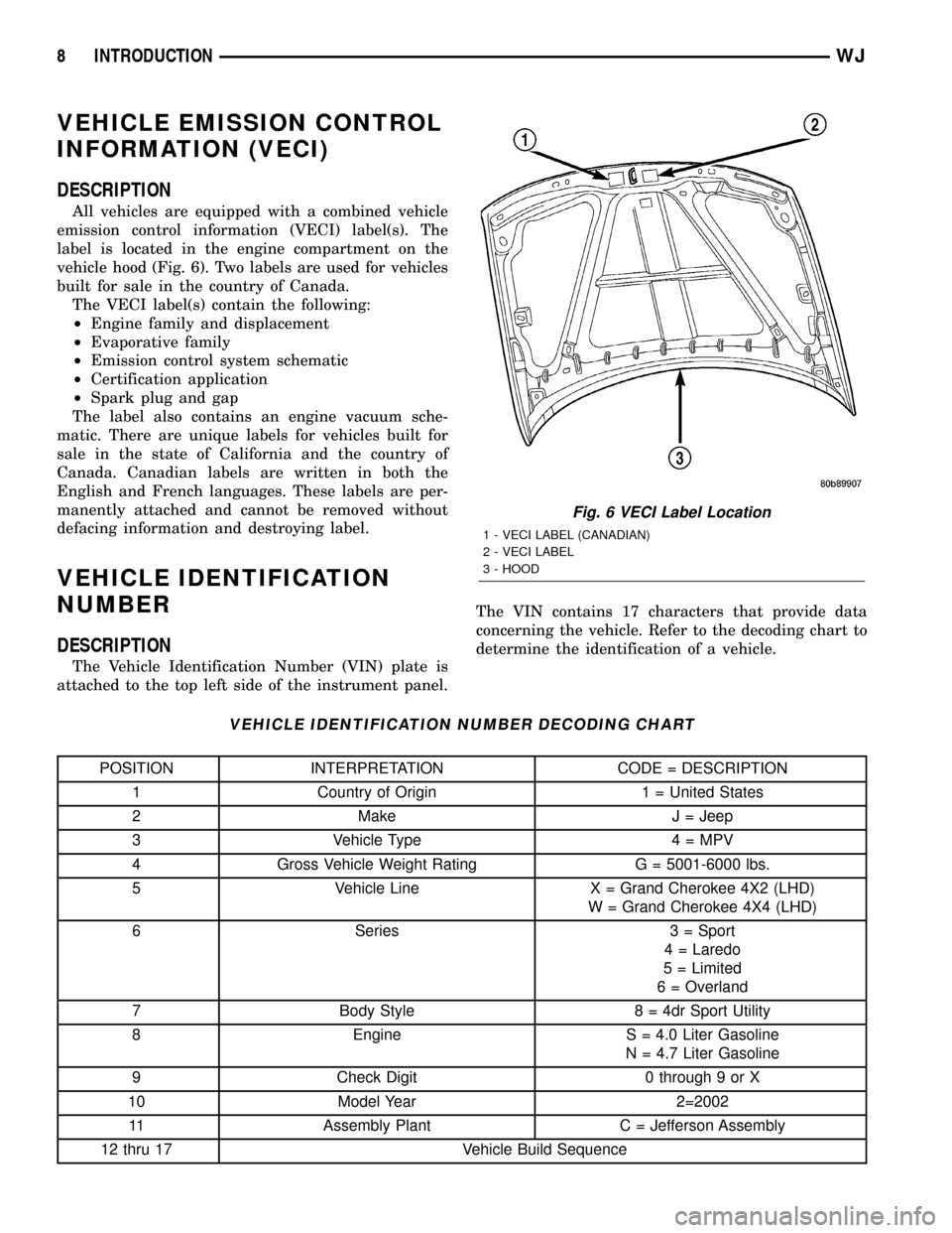
All vehicles are equipped with a combined vehicle
emission control information (VECI) label(s). The
label is located in the engine compartment on the
vehicle hood (Fig. 6). Two labels are used for vehicles
built for sale in the country of Canada.
The VECI label(s) contain the following:
²Engine family and displacement
²Evaporative family
²Emission control system schematic
²Certification application
²Spark plug and gap
The label also contains an engine vacuum sche-
matic. There are unique labels for vehicles built for
sale in the state of California and the country of
Canada. Canadian labels are written in both the
English and French languages. These labels are per-
manently attached and cannot be removed without
defacing information and destroying label.
VEHICLE IDENTIFICATION
NUMBER
DESCRIPTION
The Vehicle Identification Number (VIN) plate is
attached to the top left side of the instrument panel.The VIN contains 17 characters that provide data
concerning the vehicle. Refer to the decoding chart to
determine the identification of a vehicle.
VEHICLE IDENTIFICATION NUMBER DECODING CHART
POSITION INTERPRETATION CODE = DESCRIPTION
1 Country of Origin 1 = United States
2 Make J = Jeep
3 Vehicle Type 4 = MPV
4 Gross Vehicle Weight Rating G = 5001-6000 lbs.
5 Vehicle Line X = Grand Cherokee 4X2 (LHD)
W = Grand Cherokee 4X4 (LHD)
6 Series 3 = Sport
4 = Laredo
5 = Limited
6 = Overland
7 Body Style 8 = 4dr Sport Utility
8 Engine S = 4.0 Liter Gasoline
N = 4.7 Liter Gasoline
9 Check Digit 0 through 9 or X
10 Model Year 2=2002
11 Assembly Plant C = Jefferson Assembly
12 thru 17 Vehicle Build Sequence
Fig. 6 VECI Label Location
1 - VECI LABEL (CANADIAN)
2 - VECI LABEL
3 - HOOD
8 INTRODUCTIONWJ
Page 12 of 2199
LUBRICATION & MAINTENANCE
TABLE OF CONTENTS
page page
LUBRICATION & MAINTENANCE
SPECIFICATIONS - FLUID CAPACITIES.......1
INTERNATIONAL SYMBOLS
DESCRIPTION..........................2
PARTS & LUBRICANT RECOMMENDATION
STANDARD PROCEDURE - PARTS &
LUBRICANT RECOMMENDATIONS.........2
FLUID TYPES
DESCRIPTION
DESCRIPTION - ENGINE COOLANT........2
DESCRIPTION - ENGINE COOLANT........3
ENGINE OIL..........................4
DESCRIPTION - ENGINE OIL.............4
DESCRIPTION........................5
DESCRIPTION - TRANSFER CASE - NV242 . . 5
DESCRIPTION - TRANSFER CASE - NV247 . . 5
DESCRIPTION - AUTOMATIC
TRANSMISSION FLUID..................5
DESCRIPTION - ENGINE OIL - DIESEL
ENGINES............................6OPERATION - AUTOMATIC TRANSMISSION
FLUID...............................6
FLUID FILL/CHECK LOCATIONS
INSPECTION - FLUID FILL/CHECK
LOCATIONS..........................6
MAINTENANCE SCHEDULES
DESCRIPTION..........................6
LIFT POINTS
STANDARD PROCEDURE - HOISTING AND
JACKING RECOMMENDATIONS...........6
JUMP STARTING
STANDARD PROCEDURE - JUMP STARTING . . 7
EMERGENCY TOW HOOKS
DESCRIPTION..........................8
TOWING
STANDARD PROCEDURE - TOWING
RECOMMENDATIONS...................8
LUBRICATION &
MAINTENANCE
SPECIFICATIONS - FLUID CAPACITIES
DESCRIPTION SPECIFICATION
FUEL TANK 20 U.S. Gallons (76
Liters)****
Engine Oil - with Filter -
2.7L Diesel6.5L (6.9 qts.)
Engine Oil - with Filter -
4.0L5.7 L (6.0 qts.)
Engine Oil - with Filter -
4.7L5.7 L (6.0 qts.)
Cooling System - 2.7L
Diesel14.2L (15 qts.)***
Cooling System - 4.0L 14.1 L (15 qts.)***
Cooling System - 4.7L 13.7 L (14.5 qts.)***
AUTOMATIC TRANSMISSION
Service Fill - 42RE 3.8 L (4.0 qts.)
Service Fill - 545RFE 2WD - 5.2 L (11 pts.)
4WD - 6.2 L (13 pts.)
O-haul Fill - 42RE 9.1-9.5 L (19-20 pts.)
DESCRIPTION SPECIFICATION
O-haul Fill - 545RFE 13.33 L (28.0 pts.)
Dry fill capacity Depending on type and size of internal
cooler, length and inside diameter of cooler lines, or use
of an auxiliary cooler, these figures may vary. (Refer to
appropriate 21 - TRANSMISSION/TRANSAXLE/
AUTOMATIC/FLUID - STANDARD PROCEDURE).
TRANSFER CASE
NV242 1.35L (2.85 pts.)
NV247 1.6L (3.4 pts.)
FRONT AXLE 0.3 L (1 oz.)
186 FBI (Model 30) 1.18 L (2.5 pts.)*
* With Vari-Lok add 0.07 L (2.5 oz.) of Friction Modifier.
REAR AXLE 0.3 L (1 oz.)
198 RBI (Model 35) 1.66 L (3.5 pts.)*
226 RBA (Model 44) 2.24 L (4.75 pts.)**
* With Trac-lok add 0.07 L (2.5 oz.) of Friction Modifier.
** With Trac-lok or Vari-Lok, add 0.07 L (2.5 oz.) of
Friction Modifier.
*** Includes 0.9L (1.0 qts.) for coolant reservoir.
****Nominal refill capacities are shown. A variation may
be observed from vehicle to vehicle due to
manufacturing tolerance and refill procedure.
WJLUBRICATION & MAINTENANCE 0 - 1
Page 1205 of 2199
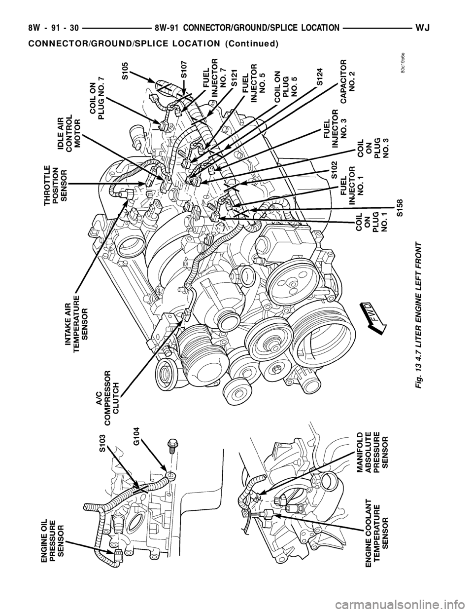
Fig. 13 4.7 LITER ENGINE LEFT FRONT
8W - 91 - 30 8W-91 CONNECTOR/GROUND/SPLICE LOCATIONWJ
CONNECTOR/GROUND/SPLICE LOCATION (Continued)
Page 1206 of 2199
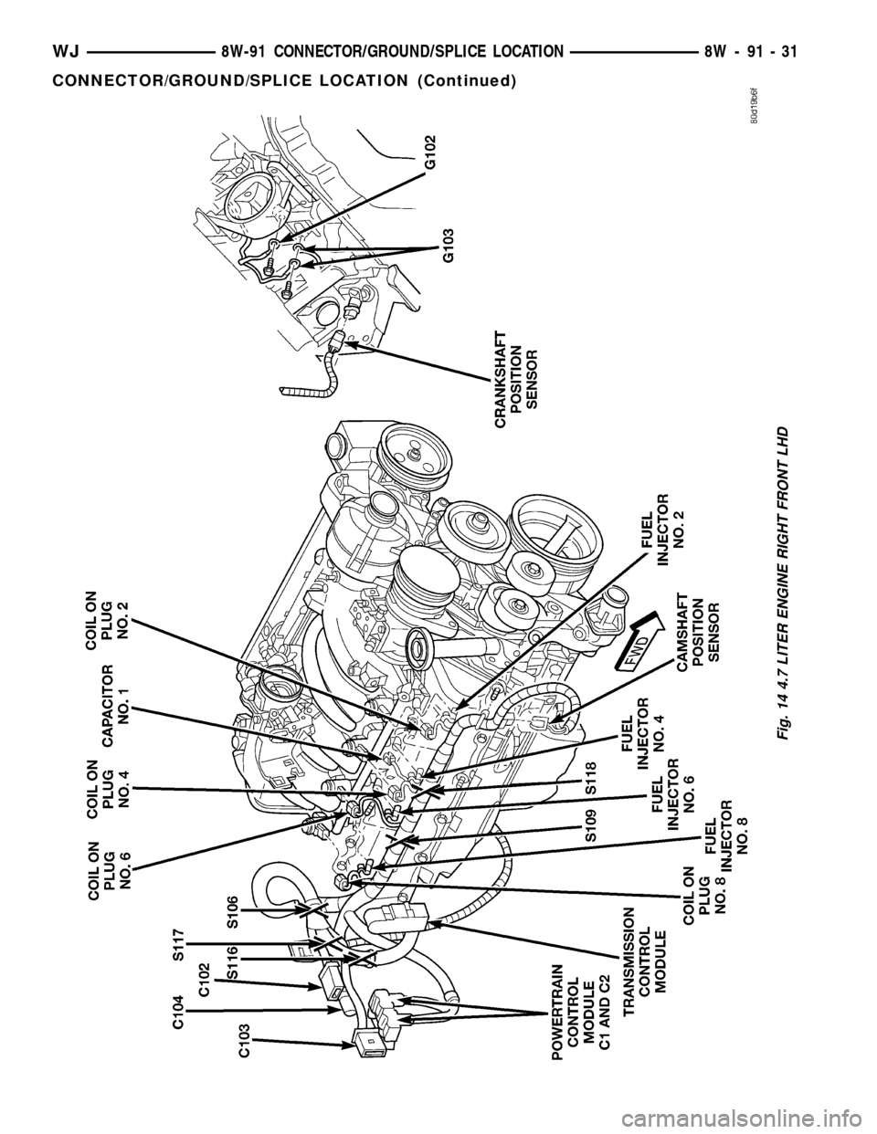
Fig. 14 4.7 LITER ENGINE RIGHT FRONT LHD
WJ8W-91 CONNECTOR/GROUND/SPLICE LOCATION 8W - 91 - 31
CONNECTOR/GROUND/SPLICE LOCATION (Continued)
Page 1207 of 2199
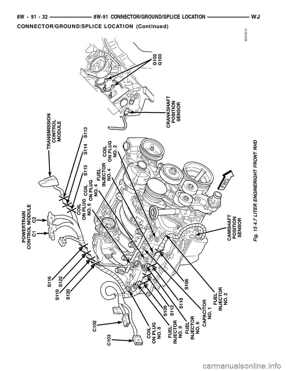
Fig. 15 4.7 LITER ENGINERIGHT FRONT RHD
8W - 91 - 32 8W-91 CONNECTOR/GROUND/SPLICE LOCATIONWJ
CONNECTOR/GROUND/SPLICE LOCATION (Continued)
Page 1208 of 2199
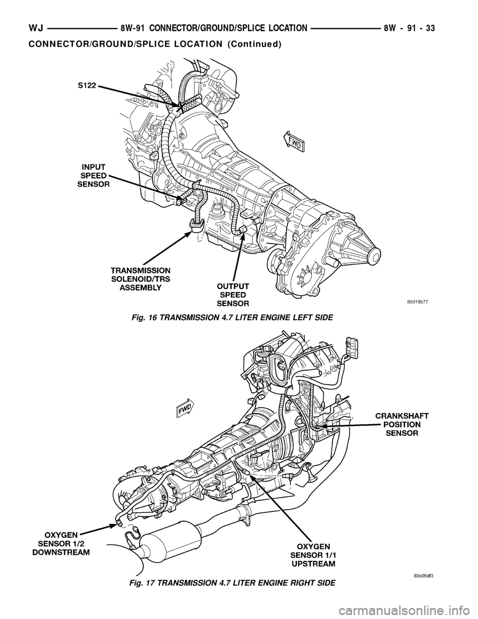
Fig. 16 TRANSMISSION 4.7 LITER ENGINE LEFT SIDE
Fig. 17 TRANSMISSION 4.7 LITER ENGINE RIGHT SIDE
WJ8W-91 CONNECTOR/GROUND/SPLICE LOCATION 8W - 91 - 33
CONNECTOR/GROUND/SPLICE LOCATION (Continued)
Page 1306 of 2199
VALVE TIMING
DESCRIPTION - TIMING DRIVE SYSTEM....141
OPERATION - TIMING DRIVE SYSTEM.....141
STANDARD PROCEDURE
STANDARD PROCEDURE - ENGINE TIMING
- VERIFICATION.....................141
STANDARD PROCEDUREÐMEASURING
TIMING CHAIN WEAR.................145TIMING BELT / CHAIN COVER(S)
REMOVAL............................146
INSTALLATION........................146
TIMING BELT/CHAIN AND SPROCKETS
REMOVAL............................147
INSPECTION.........................149
INSTALLATION........................149
ENGINE - 4.7L
DESCRIPTIONÐ4.7L ENGINE
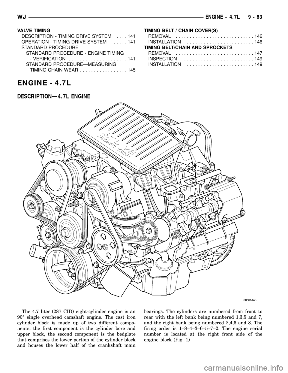
The 4.7 liter (287 CID) eight-cylinder engine is an
90É single overhead camshaft engine. The cast iron
cylinder block is made up of two different compo-
nents; the first component is the cylinder bore and
upper block, the second component is the bedplate
that comprises the lower portion of the cylinder block
and houses the lower half of the crankshaft mainbearings. The cylinders are numbered from front to
rear with the left bank being numbered 1,3,5 and 7,
and the right bank being numbered 2,4,6 and 8. The
firing order is 1±8±4±3±6±5±7±2. The engine serial
number is located at the right front side of the
engine block (Fig. 1)
WJENGINE - 4.7L 9 - 63
Page 1317 of 2199
²Camshaft Position (CMP) Sensor
²Coil Over Plugs
(10) Install generator (Refer to 8 - ELECTRICAL/
CHARGING/GENERATOR - INSTALLATION).
(11) Install radiator (Refer to 7 - COOLING/EN-
GINE/RADIATOR - INSTALLATION).
(12) Install A/C condenser (Refer to 24 - HEATING
& AIR CONDITIONING/PLUMBING/A/C CON-
DENSER - INSTALLATION).
(13) Connect radiator lower hose at the thermostat
housing.
(14) Connect the transmission oil cooler lines to
the radiator.
(15) Install A/C compressor. (Refer to 24 - HEAT-
ING & AIR CONDITIONING/PLUMBING/A/C COM-
PRESSOR - INSTALLATION).
(16) Install accessory drive belt (Refer to 7 -
COOLING/ACCESSORY DRIVE/DRIVE BELTS -
INSTALLATION) and radiator fan (Refer to 7 -
COOLING/ENGINE/RADIATOR FAN - INSTALLA-
TION).
(17) Install breathers, then connect tube to both
crankcase breathers (Fig. 5).
(18) Connect throttle and speed control cables.
(19) Install throttle body resonator assembly and
inlet hose.
(20) Raise vehicle.
(21) Connect two ground straps on the lower left
hand side of the engine and one ground strap on the
lower right side.
(22) Install torque converter bolts.
(23) Connect crankshaft position sensor (Fig. 4).
(24) Install starter.
(25) Install rubber splash shield.
CAUTION: The structural cover requires a specific
torque sequence. Failure to follow this sequence
may cause severe damage to the cover.
(26) Install structural cover (Refer to 9 - ENGINE/
ENGINE BLOCK/STRUCTURAL COVER - INSTAL-
LATION).
(27) Install exhaust crossover pipe.
(28) Install engine block heater power cable, If
equipped.
(29) Lower vehicle.
(30) Check and fill engine oil (Refer to LUBRICA-
TION & MAINTENANCE/FLUID TYPES - SPECIFI-
CATIONS).
(31) Recharge the A/C system (Refer to 24 - HEAT-
ING & AIR CONDITIONING/PLUMBING - STAN-
DARD PROCEDURE).
(32) Refill the engine cooling system (Refer to 7 -
COOLING - STANDARD PROCEDURE).
(33) Connect the battery negative cable.
(34) Start engine and check for leaks.SPECIFICATIONS
4.7L ENGINE
DESCRIPTION SPECIFICATION
GENERAL SPECIFICATIONS
Engine Type 90É SOHC V-8 16-Valve
Displacement 4.7 Liters / 4701cc
(287 Cubic Inches)
Bore 93.0 mm (3.66 in.)
Stroke 86.5 mm (3.40 in.)
Compression Ratio 9.0:1
Horsepower 235 BHP @ 4800 RPM
Torque 295 LB-FT @ 3200 RPM
Lead Cylinder #1 Left Bank
Firing Order 1-8-4-3-6-5-7-2
CYLINDER BLOCK
Cylinder Block Cast Iron
Bore Diameter 93.010 .0075 mm
(3.6619 0.0003 in.)
Out of Round (MAX) 0.076 mm (0.003 in.)
Taper (MAX) 0.051 mm (0.002 in.)
PISTONS
Material Aluminum Alloy
Diameter 92.975 mm (3.6605 in.)
Weight 367.5 grams (12.96 oz)
Ring Groove Diameter
No. 1 83.73 - 83.97 mm
(3.296 - 3.269 in.)
No. 2 82.833 - 83.033 mm
(3.261 - 3.310 in.)
No. 3 83.88 - 84.08 mm
(3.302 - 3.310 in.)
PISTON PINS
Type Pressed Fit
Clearance In Piston 0.010 - 0.019 mm
(0.0004 - 0.0008 in.)
Diameter 24.013 - 24.016 mm
(0.9454 - 0.9456 in.)
9 - 74 ENGINE - 4.7LWJ
ENGINE - 4.7L (Continued)
Page 1320 of 2199
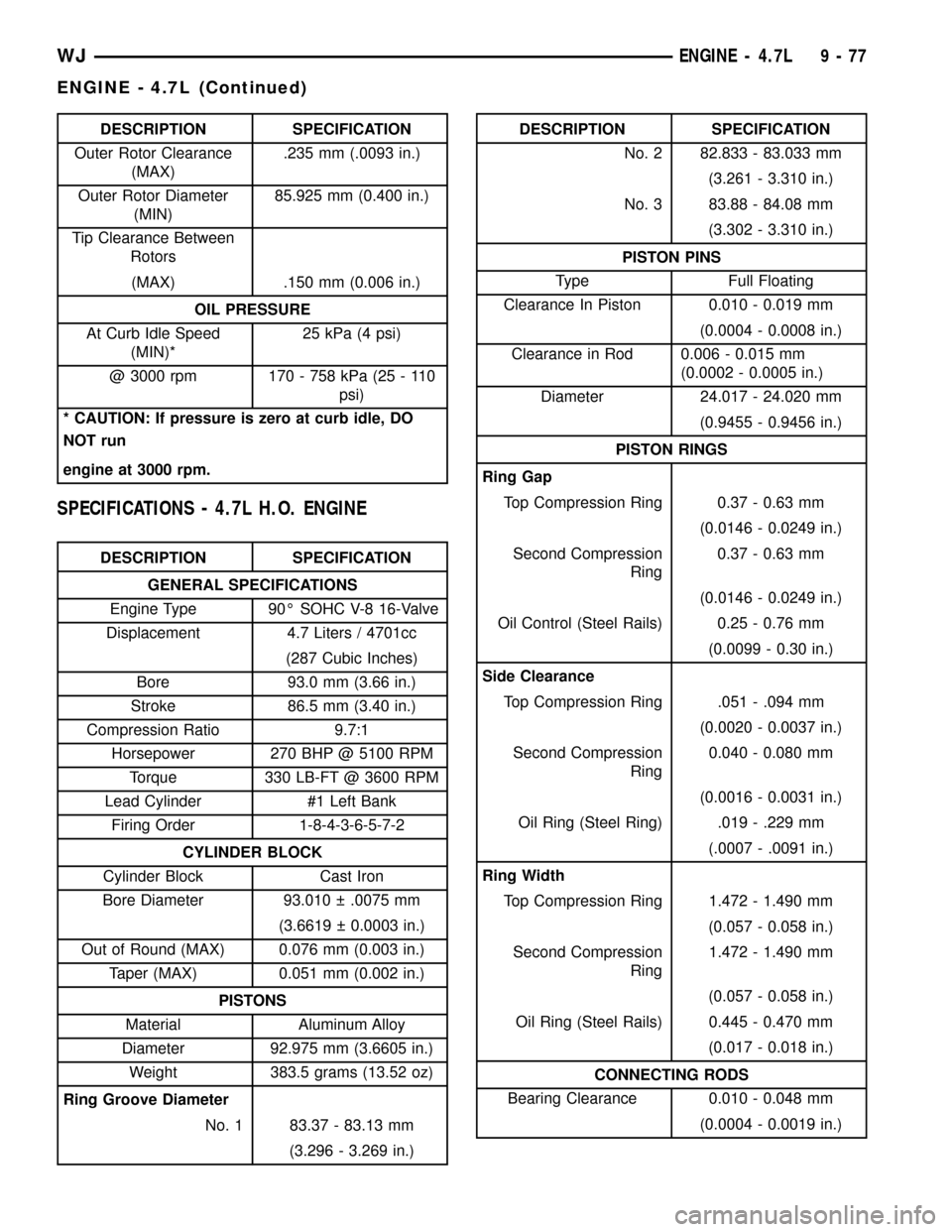
DESCRIPTION SPECIFICATION
Outer Rotor Clearance
(MAX).235 mm (.0093 in.)
Outer Rotor Diameter
(MIN)85.925 mm (0.400 in.)
Tip Clearance Between
Rotors
(MAX) .150 mm (0.006 in.)
OIL PRESSURE
At Curb Idle Speed
(MIN)*25 kPa (4 psi)
@ 3000 rpm 170 - 758 kPa (25 - 110
psi)
* CAUTION: If pressure is zero at curb idle, DO
NOT run
engine at 3000 rpm.
SPECIFICATIONS - 4.7L H.O. ENGINE
DESCRIPTION SPECIFICATION
GENERAL SPECIFICATIONS
Engine Type 90É SOHC V-8 16-Valve
Displacement 4.7 Liters / 4701cc
(287 Cubic Inches)
Bore 93.0 mm (3.66 in.)
Stroke 86.5 mm (3.40 in.)
Compression Ratio 9.7:1
Horsepower 270 BHP @ 5100 RPM
Torque 330 LB-FT @ 3600 RPM
Lead Cylinder #1 Left Bank
Firing Order 1-8-4-3-6-5-7-2
CYLINDER BLOCK
Cylinder Block Cast Iron
Bore Diameter 93.010 .0075 mm
(3.6619 0.0003 in.)
Out of Round (MAX) 0.076 mm (0.003 in.)
Taper (MAX) 0.051 mm (0.002 in.)
PISTONS
Material Aluminum Alloy
Diameter 92.975 mm (3.6605 in.)
Weight 383.5 grams (13.52 oz)
Ring Groove Diameter
No. 1 83.37 - 83.13 mm
(3.296 - 3.269 in.)
DESCRIPTION SPECIFICATION
No. 2 82.833 - 83.033 mm
(3.261 - 3.310 in.)
No. 3 83.88 - 84.08 mm
(3.302 - 3.310 in.)
PISTON PINS
Type Full Floating
Clearance In Piston 0.010 - 0.019 mm
(0.0004 - 0.0008 in.)
Clearance in Rod 0.006 - 0.015 mm
(0.0002 - 0.0005 in.)
Diameter 24.017 - 24.020 mm
(0.9455 - 0.9456 in.)
PISTON RINGS
Ring Gap
Top Compression Ring 0.37 - 0.63 mm
(0.0146 - 0.0249 in.)
Second Compression
Ring0.37 - 0.63 mm
(0.0146 - 0.0249 in.)
Oil Control (Steel Rails) 0.25 - 0.76 mm
(0.0099 - 0.30 in.)
Side Clearance
Top Compression Ring .051 - .094 mm
(0.0020 - 0.0037 in.)
Second Compression
Ring0.040 - 0.080 mm
(0.0016 - 0.0031 in.)
Oil Ring (Steel Ring) .019 - .229 mm
(.0007 - .0091 in.)
Ring Width
Top Compression Ring 1.472 - 1.490 mm
(0.057 - 0.058 in.)
Second Compression
Ring1.472 - 1.490 mm
(0.057 - 0.058 in.)
Oil Ring (Steel Rails) 0.445 - 0.470 mm
(0.017 - 0.018 in.)
CONNECTING RODS
Bearing Clearance 0.010 - 0.048 mm
(0.0004 - 0.0019 in.)
WJENGINE - 4.7L 9 - 77
ENGINE - 4.7L (Continued)