8-1 JEEP GRAND CHEROKEE 2002 WJ / 2.G Workshop Manual
[x] Cancel search | Manufacturer: JEEP, Model Year: 2002, Model line: GRAND CHEROKEE, Model: JEEP GRAND CHEROKEE 2002 WJ / 2.GPages: 2199, PDF Size: 76.01 MB
Page 642 of 2199

stalk is moved to the rear Wash position, the Wash
position circuitry within the switch directs battery
current to the rear washer pump/motor unit, and to
both the rear wiper motor control and rear washer
switch output signal inputs of the rear wiper module
electronic circuitry, which causes the wiper motor to
run at a fixed cycle for as long as the Wash mode is
selected plus about three additional fixed wipe cycles.
The rear wiper module electronic circuitry controls
the switching of battery current to the rear wiper
motor brush, which controls wiper motor operation.
The intermittent wipe and wipe-after-wash features
of the rear wiper and washer system are both pro-
vided by the rear wiper module electronic circuitry.
The rear wiper module electronic circuitry also mon-
itors the liftgate flip-up glass ajar switch and will
park the rear wiper blade off of the glass any time it
senses that the liftgate flip-up glass is ajar, the igni-
tion switch is turned to the Off position, or the right
multi-function switch control sleeve is moved to the
Off position. This feature ensures that the rear wiper
blade will not interfere with or be damaged by the
operation of the liftgate flip-up glass. However, if the
ignition switch is turned to the Off position or the
liftgate flip-up glass is opened while the rear wiper is
operating, the right multi-function switch control
sleeve must be cycled to the Off position and back to
the On or Delay position after the ignition switch is
turned back On or the liftgate flip-up glass is closed
before the rear wiper will operate again.
Refer to the owner's manual in the vehicle glove
box for more information on the features and opera-
tion of the rear wiper and washer system.
DIAGNOSIS AND TESTING - REAR WIPER &
WASHER SYSTEM
WIPER SYSTEM
The diagnosis found here addresses an electrically
inoperative rear wiper system. If the rear wiper
motor operates, but the wiper does not move on the
liftgate glass, replace the faulty rear wiper module. If
the wiper operates, but chatters, lifts, or does not
clear the glass, clean and inspect the wiper system
components as required. (Refer to 8 - ELECTRICAL/
REAR WIPERS/WASHERS - INSPECTION) and
(Refer to 8 - ELECTRICAL/REAR WIPERS/WASH-
ERS - CLEANING). Refer to the appropriate wiring
information. The wiring information includes wiring
diagrams, proper wire and connector repair proce-
dures, details of wire harness routing and retention,
connector pin-out information and location views for
the various wire harness connectors, splices and
grounds.WARNING: ON VEHICLES EQUIPPED WITH AIR-
BAGS, DISABLE THE AIRBAG SYSTEM BEFORE
ATTEMPTING ANY STEERING WHEEL, STEERING
COLUMN, OR INSTRUMENT PANEL COMPONENT
DIAGNOSIS OR SERVICE. DISCONNECT AND ISO-
LATE THE BATTERY NEGATIVE (GROUND) CABLE,
THEN WAIT TWO MINUTES FOR THE AIRBAG SYS-
TEM CAPACITOR TO DISCHARGE BEFORE PER-
FORMING FURTHER DIAGNOSIS OR SERVICE. THIS
IS THE ONLY SURE WAY TO DISABLE THE AIRBAG
SYSTEM. FAILURE TO TAKE THE PROPER PRE-
CAUTIONS COULD RESULT IN ACCIDENTAL AIR-
BAG DEPLOYMENT AND POSSIBLE PERSONAL
INJURY.
(1) Check that the interior lighting switch on the
control stalk of the left multi-function switch is not
in the dome lamp disable position. With all four
doors and the liftgate closed, open the liftgate flip-up
glass. The interior lamps should light. If not, depress
the cargo lamp lens to actuate the cargo lamp defeat
switch and the interior lamps should light. Close all
four doors, the liftgate and the liftgate flip-up glass.
Note whether the interior lamps remain lighted.
They should turn off after about thirty seconds. If
OK, go to Step 2. If not OK, go to Step 9.
(2) Check the fused B(+) fuse (Fuse8-15ampere)
in the Junction Block (JB). If OK, go to Step 3. If not
OK, repair the shorted circuit or component as
required and replace the faulty fuse.
(3) Check for battery voltage at the fused B(+) fuse
(Fuse8-15ampere) in the JB. If OK, go to Step 4. If
not OK, repair the open fused B(+) circuit between
the JB and the Power Distribution Center (PDC) as
required.
(4) Check the fused ignition switch output (run-
acc) fuse (Fuse 29 - 10 ampere) in the JB. If OK, go
to Step 5. If not OK, repair the shorted circuit or
component as required and replace the faulty fuse.
(5) Turn the ignition switch to the On position.
Check for battery voltage at the fused ignition switch
output (run-acc) fuse (Fuse 29 - 10 ampere) in the
JB. If OK, turn the ignition switch to the Off position
and go to Step 6. If not OK, repair the open fused
ignition switch output (run-acc) circuit between the
JB and the ignition switch as required.
(6) Disconnect and isolate the battery negative
cable. Disconnect the instrument panel wire harness
connector for the right multi-function switch from the
switch connector receptacle. Reconnect the battery
negative cable. Turn the ignition switch to the On
position. Check for battery voltage at the fused igni-
tion switch output (run-acc) circuit cavity of the
instrument panel wire harness connector for the
right multi-function switch. If OK, go to Step 7. If
not OK, repair the open fused ignition switch output
WJREAR WIPERS/WASHERS 8R - 35
REAR WIPERS/WASHERS (Continued)
Page 654 of 2199

WIRING
TABLE OF CONTENTS
page page
WIRING DIAGRAM INFORMATION....... 8W-01-1
COMPONENT INDEX.................. 8W-02-1
POWER DISTRIBUTION............... 8W-10-1
JUNCTION BLOCK.................... 8W-12-1
GROUND DISTRIBUTION.............. 8W-15-1
BUS COMMUNICATIONS.............. 8W-18-1
CHARGING SYSTEM.................. 8W-20-1
STARTING SYSTEM.................. 8W-21-1
FUEL/IGNITION SYSTEM.............. 8W-30-1
TRANSMISSION CONTROL SYSTEM..... 8W-31-1
VEHICLE SPEED CONTROL............ 8W-33-1
ANTILOCK BRAKES................... 8W-35-1
VEHICLE THEFT SECURITY SYSTEM..... 8W-39-1
INSTRUMENT CLUSTER............... 8W-40-1
HORN/CIGAR LIGHTER/POWER OUTLET . . 8W-41-1
AIR CONDITIONING-HEATER........... 8W-42-1
AIRBAG SYSTEM.................... 8W-43-1
INTERIOR LIGHTING.................. 8W-44-1
BODY CONTROL MODULE............. 8W-45-1AUDIO SYSTEM..................... 8W-47-1
REAR WINDOW DEFOGGER............ 8W-48-1
OVERHEAD CONSOLE................. 8W-49-1
FRONT LIGHTING.................... 8W-50-1
REAR LIGHTING..................... 8W-51-1
TURN SIGNALS...................... 8W-52-1
WIPERS............................ 8W-53-1
TRAILER TOW....................... 8W-54-1
POWER WINDOWS................... 8W-60-1
POWER DOOR LOCKS................ 8W-61-1
POWER MIRRORS................... 8W-62-1
POWER SEATS...................... 8W-63-1
POWER SUNROOF................... 8W-64-1
SPLICE INFORMATION................ 8W-70-1
CONNECTOR PIN-OUT................ 8W-80-1
CONNECTOR/GROUND/SPLICE
LOCATION........................ 8W-91-1
POWER DISTRIBUTION............... 8W-97-1 WJWIRING 8W - 1
Page 1040 of 2199

8W-70 SPLICE INFORMATION
Component PageS100.............................8W-10-11, 12
S102.............................8W-30-21, 45
S104................................8W-15-4
S105...............................8W-30-20
S106.............................8W-10-19, 20
S107............................8W-70-2, 3, 4, 5
S109...............................8W-10-21
S110 ................................8W-70-2
S111................................8W-10-23
S112............................8W-70-2, 3, 4, 5
S113................................8W-31-13
S114 ................................8W-15-2
S115................................8W-10-17
S116................................8W-12-18
S118................................8W-10-22
S119 ..............................8W-31-9, 10
S120...............................8W-30-20
S121...............................8W-10-21
S122...............................8W-31-5, 6
S123.............................8W-10-19, 20
S123...............................8W-30-12
S124...............................8W-10-22
S125................................8W-30-6
S126...............................8W-30-23
S127...............................8W-10-27
S128.............................8W-10-19, 20
S130...............................8W-18-3, 5
S131...............................8W-70-6, 7
S132............................8W-15-9, 10, 11
S133............................8W-15-9, 10, 11
S134...............................8W-15-6, 7
S135...............................8W-10-18
S136...............................8W-10-18
S137...............................8W-10-31
S139................................8W-15-3
S140................................8W-15-7
S141................................8W-15-6
S142..............................8W-12-3, 32
S143..............................8W-12-5, 32
S145................................8W-70-6
S147...............................8W-30-51
S151................................8W-15-5
S152................................8W-15-8
S153...............................8W-12-14
S154...............................8W-12-33
S155...............................8W-12-33
S156...............................8W-12-14
S158................................8W-70-5
S160................................8W-30-11
S162...............................8W-10-26
S163..............................8W-12-7, 15
S165................................8W-51-9
S168...............................8W-10-26
S169...............................8W-30-47
S170...............................8W-30-44
S171...............................8W-30-36
S172...............................8W-30-36
S174................................8W-15-6
S175................................8W-21-2
S176...............................8W-10-26
S200...............................8W-63-12
S201...............................8W-15-15
S202...............................8W-44-10
S203...............................8W-15-14
S204...............................8W-12-22
S205...............................8W-15-15
S206...............................8W-12-22
S207...............................8W-12-16
S208................................8W-44-8
S209................................8W-12-11
S210...............................8W-18-4, 7
S211................................8W-15-13
S212................................8W-53-2
S213................................8W-33-5
S214................................8W-33-5
S215...............................8W-47-13
S216...............................8W-47-13
S217...............................8W-18-10Component PageS221................................8W-12-11
S222...............................8W-30-37
S223............................8W-18-8, 9, 10
S224.............................8W-15-17, 18
S300...............................8W-15-21
S301...............................8W-15-21
S302...............................8W-61-5, 6
S303...............................8W-61-5, 6
S304...............................8W-12-16
S305...............................8W-18-2, 6
S306...............................8W-12-27
S307...............................8W-15-19
S308...............................8W-12-36
S309...............................8W-12-12
S310...............................8W-51-7, 8
S311 ................................8W-51-5
S312...............................8W-18-2, 6
S313...............................8W-51-5, 6
S314................................8W-33-2
S315...............................8W-70-6, 7
S316...............................8W-12-18
S317................................8W-61-5
S318................................8W-61-5
S319...............................8W-12-21
S323................................8W-18-9
S324...............................8W-18-3, 5
S326.............................8W-12-12, 13
S327...............................8W-12-32
S328................................8W-51-7
S329...............................8W-15-17
S330...............................8W-15-16
S331.............................8W-15-17, 18
S332.............................8W-15-17, 18
S333................................8W-47-3
S334................................8W-12-11
S336...............................8W-15-16
S337...............................8W-12-25
S338...............................8W-15-16
S339...............................8W-61-5, 6
S340...............................8W-61-5, 6
S341.............................8W-15-17, 22
S342................................8W-12-9
S345...............................8W-15-19
S346...............................8W-12-16
S347...............................8W-12-30
S348...............................8W-12-24
S349...............................8W-12-23
S351................................8W-70-8
S352................................8W-63-8
S353................................8W-12-9
S355.............................8W-15-18, 21
S356.............................8W-15-21, 22
S357.............................8W-15-16, 18
S358...............................8W-15-22
S359................................8W-50-9
S360................................8W-47-4
S361................................8W-47-4
S362................................8W-47-4
S363................................8W-47-4
S364................................8W-18-5
S365................................8W-39-11
S366...............................8W-12-15
S367...............................8W-12-36
S368................................8W-47-3
S369.............................8W-15-21, 22
S370...............................8W-15-19
S400...............................8W-12-17
S401...............................8W-15-20
S402...............................8W-15-20
S403...............................8W-12-16
S404...............................8W-12-30
S405...............................8W-12-30
S406................................8W-54-6
S407................................8W-54-6
S408...............................8W-15-19
S410...............................8W-15-19
S411 .............................8W-12-12, 13
S412...............................8W-15-20
WJ8W-70 SPLICE INFORMATION 8W - 70 - 1
Page 1261 of 2199
DESCRIPTION N´m Ft. In.
Lbs. Lbs.
Transmission Support Bracket
ÐBolt (Manual) 46 34 Ð
Transmission Support Bracket/
CushionÐBolt (4WD Auto) 75 55 Ð
Transmission Support Adaptor
BracketÐBolts (2WD Auto) 75 55 Ð
Exhaust Manifold/PipeÐNuts 27 20 Ð
Intake/Exhaust Manifold
Fasteners #1-5 33 24 Ð
Fasteners #6 and 7 14 Ð 126
Fasteners #8-11 33 24 Ð
Flywheel to Converter
HousingÐBolts38 28 Ð
Flywheel to CrankshaftÐBolts 143 105 Ð
Front Cover to BlockÐBolts
1/4-20 7 Ð 60
5/16-18 22 Ð 192
Fuel RailÐBolts/Stud 12 Ð 108
GeneratorÐBolts 57 42 Ð
Generator Bracket to EngineÐ
Bolts47 35 Ð
Idler Pulley to Cylinder
HeadÐBolt47 35 Ð
Main Bearing CapÐBolts 108 80 Ð
Oil Filter 18 Ð 156
Oil Filter Connector to
Adaptor 47 35 Ð
Block 68 50 Ð
Adaptor Bolts 102 50 Ð
Oil GalleyÐPlug 41 30 Ð
Oil PanÐBolts
1/4-20 9.5 Ð 84
5/16-18 15 Ð 132
Oil PanÐDrain Plug 34 25 Ð
Oil Pump
Mounting Bolts 23 Ð 204
Cover Bolts 8 Ð 70
Rocker Arm Assembly to
Cylinder
HeadÐCapscrews 30 21 Ð
Spark Plugs 37 27 ÐDESCRIPTION N´m Ft. In.
Lbs. Lbs.
Starter MotorÐMounting Bolts 45 33 Ð
Thermostat HousingÐBolts 18 Ð 156
Throttle BodyÐBolts 10 Ð 90
Vibration DamperÐBolt 108 80 Ð
Water Pump to BlockÐBolts 23 17 Ð
AIR CLEANER ELEMENT
REMOVAL - 4.0L
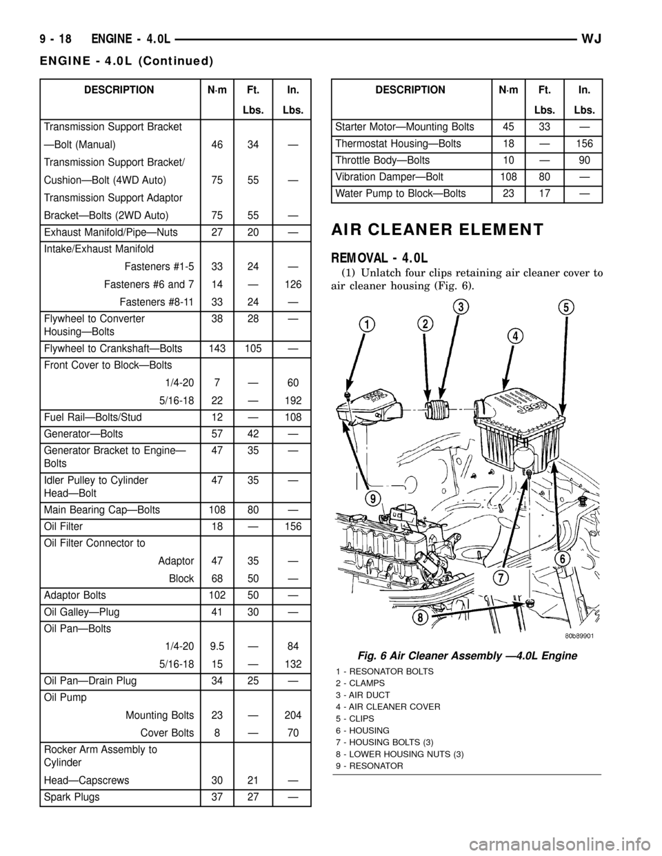
(1) Unlatch four clips retaining air cleaner cover to
air cleaner housing (Fig. 6).
Fig. 6 Air Cleaner Assembly Ð4.0L Engine
1 - RESONATOR BOLTS
2 - CLAMPS
3 - AIR DUCT
4 - AIR CLEANER COVER
5 - CLIPS
6 - HOUSING
7 - HOUSING BOLTS (3)
8 - LOWER HOUSING NUTS (3)
9 - RESONATOR
9 - 18 ENGINE - 4.0LWJ
ENGINE - 4.0L (Continued)
Page 1763 of 2199
(23) Install the reverse clutch pack into the input
clutch retainer (Fig. 77).
(24) Install the reverse reaction plate into the
input clutch retainer.
(25) Install the reverse reaction plate selective
snap-ring into the input clutch retainer.
(26) Mount a dial indicator to the assembly, push
down on the clutch discs, pull up on the reaction
plate to ensure the plate is properly seated and zero
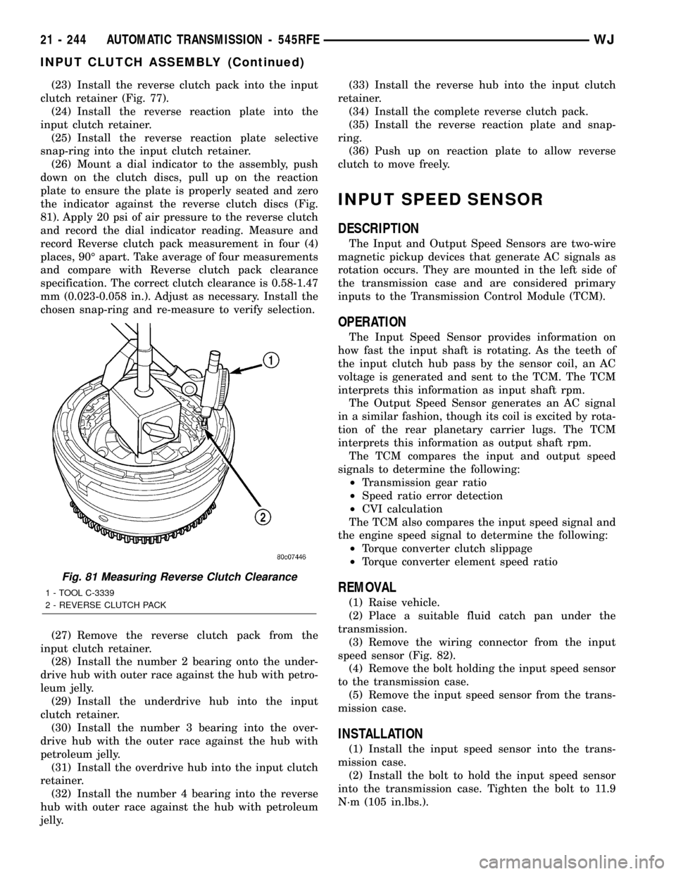
the indicator against the reverse clutch discs (Fig.
81). Apply 20 psi of air pressure to the reverse clutch
and record the dial indicator reading. Measure and
record Reverse clutch pack measurement in four (4)
places, 90É apart. Take average of four measurements
and compare with Reverse clutch pack clearance
specification. The correct clutch clearance is 0.58-1.47
mm (0.023-0.058 in.). Adjust as necessary. Install the
chosen snap-ring and re-measure to verify selection.
(27) Remove the reverse clutch pack from the
input clutch retainer.
(28) Install the number 2 bearing onto the under-
drive hub with outer race against the hub with petro-
leum jelly.
(29) Install the underdrive hub into the input
clutch retainer.
(30) Install the number 3 bearing into the over-
drive hub with the outer race against the hub with
petroleum jelly.
(31) Install the overdrive hub into the input clutch
retainer.
(32) Install the number 4 bearing into the reverse
hub with outer race against the hub with petroleum
jelly.(33) Install the reverse hub into the input clutch
retainer.
(34) Install the complete reverse clutch pack.
(35) Install the reverse reaction plate and snap-
ring.
(36) Push up on reaction plate to allow reverse
clutch to move freely.
INPUT SPEED SENSOR
DESCRIPTION
The Input and Output Speed Sensors are two-wire
magnetic pickup devices that generate AC signals as
rotation occurs. They are mounted in the left side of
the transmission case and are considered primary
inputs to the Transmission Control Module (TCM).
OPERATION
The Input Speed Sensor provides information on
how fast the input shaft is rotating. As the teeth of
the input clutch hub pass by the sensor coil, an AC
voltage is generated and sent to the TCM. The TCM
interprets this information as input shaft rpm.
The Output Speed Sensor generates an AC signal
in a similar fashion, though its coil is excited by rota-
tion of the rear planetary carrier lugs. The TCM
interprets this information as output shaft rpm.
The TCM compares the input and output speed
signals to determine the following:
²Transmission gear ratio
²Speed ratio error detection
²CVI calculation
The TCM also compares the input speed signal and
the engine speed signal to determine the following:
²Torque converter clutch slippage
²Torque converter element speed ratio
REMOVAL
(1) Raise vehicle.
(2) Place a suitable fluid catch pan under the
transmission.
(3) Remove the wiring connector from the input
speed sensor (Fig. 82).
(4) Remove the bolt holding the input speed sensor
to the transmission case.
(5) Remove the input speed sensor from the trans-
mission case.
INSTALLATION
(1) Install the input speed sensor into the trans-
mission case.
(2) Install the bolt to hold the input speed sensor
into the transmission case. Tighten the bolt to 11.9
N´m (105 in.lbs.).
Fig. 81 Measuring Reverse Clutch Clearance
1 - TOOL C-3339
2 - REVERSE CLUTCH PACK
21 - 244 AUTOMATIC TRANSMISSION - 545RFEWJ
INPUT CLUTCH ASSEMBLY (Continued)
Page 1827 of 2199
SPECIFICATIONS
TRANSFER CASE - NV242
TORQUE SPECIFICATIONS
DESCRIPTION N´m Ft. Lbs. In. Lbs.
Plug, Detent 16-24 11.8-17.7 -
Bolt, Diff. Case 17-27 12.5-19.9 -
Plug, Drain/Fill 20-34 15-25 -
Bolt, Front Brg. Retainer 16-27 11.8-19.9 -
Bolt, Case Half 35-46 25.8-33.9 -
Nut, Front Yoke 122-176 90-130 -
Screw, Oil Pump 1.2-1.8 - 12-15
Nut, Range Lever 27-34 19.9-25 -
Bolt, Rear Retainer 35-46 25.8-33.9 -
Nuts, Mounting 35 25.8 -
Bolts, U-Joint 19 14 -
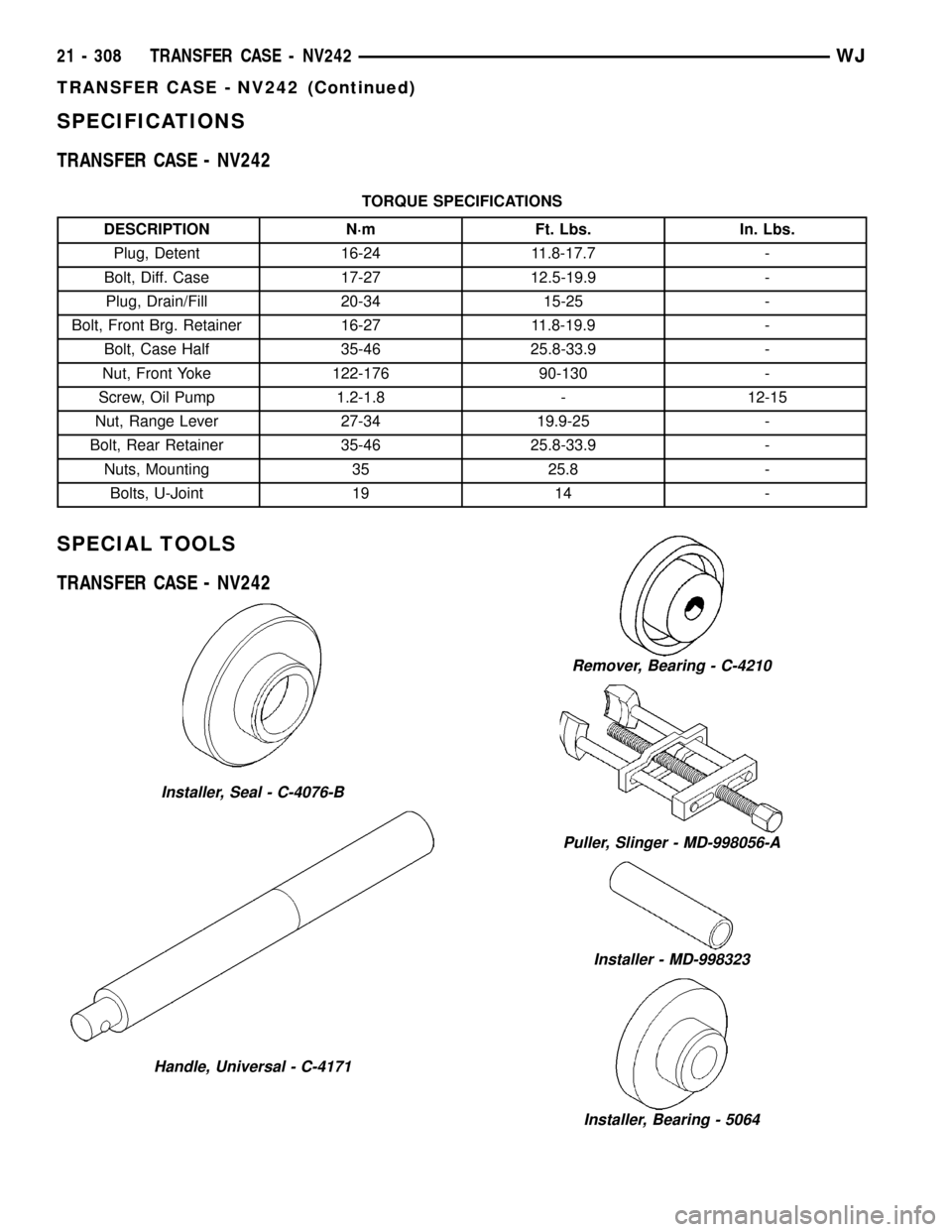
SPECIAL TOOLS
TRANSFER CASE - NV242
Installer, Seal - C-4076-B
Handle, Universal - C-4171
Remover, Bearing - C-4210
Puller, Slinger - MD-998056-A
Installer - MD-998323
Installer, Bearing - 5064
21 - 308 TRANSFER CASE - NV242WJ
TRANSFER CASE - NV242 (Continued)
Page 1855 of 2199
(6) Connect front propeller shaft and install rear
propeller shaft. (Refer to 3 - DIFFERENTIAL &
DRIVELINE/PROPELLER SHAFT/PROPELLER
SHAFT - INSTALLATION)
(7) Fill transfer case with correct fluid. Check
transmission fluid level. Correct as necessary.
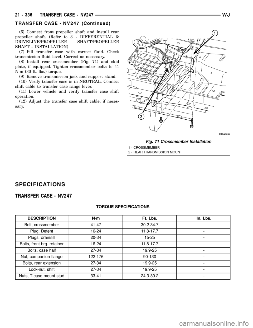
(8) Install rear crossmember (Fig. 71) and skid
plate, if equipped. Tighten crossmember bolts to 41
N´m (30 ft. lbs.) torque.
(9) Remove transmission jack and support stand.
(10) Verify transfer case is in NEUTRAL. Connect
shift cable to transfer case range lever.
(11) Lower vehicle and verify transfer case shift
operation.
(12) Adjust the transfer case shift cable, if neces-
sary.
SPECIFICATIONS
TRANSFER CASE - NV247
TORQUE SPECIFICATIONS
DESCRIPTION N´m Ft. Lbs. In. Lbs.
Bolt, crossmember 41-47 30.2-34.7 -
Plug, Detent 16-24 11.8-17.7 -
Plugs, drain/fill 20-34 15-25 -
Bolts, front brg. retainer 16-24 11.8-17.7 -
Bolts, case half 27-34 19.9-25 -
Nut, companion flange 122-176 90-130 -
Bolts, rear extension 27-34 19.9-25 -
Lock-nut, shift 27-34 19.9-25 -
Nuts, T-case mount stud 33-41 24.3-30.2 -
Fig. 71 Crossmember Installation
1 - CROSSMEMBER
2 - REAR TRANSMISSION MOUNT
21 - 336 TRANSFER CASE - NV247WJ
TRANSFER CASE - NV247 (Continued)
Page 1953 of 2199
INSTALLATION
(1) Position the bin hooks high in the slots on the
quarter trim panel.
(2) Push downward until the bin snaps into place.
(3) Install the hinge screws.
REAR VIEW MIRROR
REMOVAL
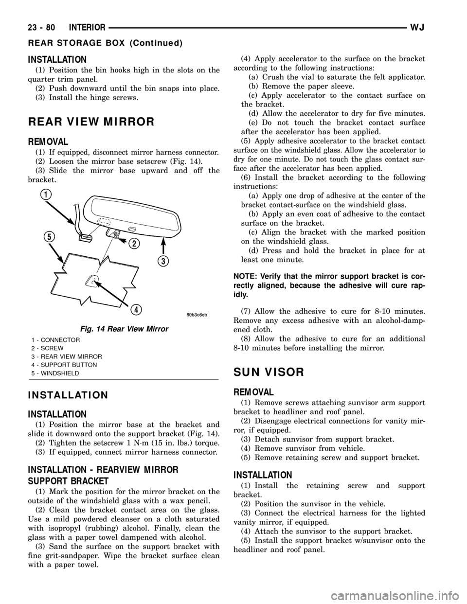
(1)If equipped, disconnect mirror harness connector.
(2) Loosen the mirror base setscrew (Fig. 14).
(3) Slide the mirror base upward and off the
bracket.
INSTALLATION
INSTALLATION
(1) Position the mirror base at the bracket and
slide it downward onto the support bracket (Fig. 14).
(2) Tighten the setscrew 1 N´m (15 in. lbs.) torque.
(3) If equipped, connect mirror harness connector.
INSTALLATION - REARVIEW MIRROR
SUPPORT BRACKET
(1) Mark the position for the mirror bracket on the
outside of the windshield glass with a wax pencil.
(2) Clean the bracket contact area on the glass.
Use a mild powdered cleanser on a cloth saturated
with isopropyl (rubbing) alcohol. Finally, clean the
glass with a paper towel dampened with alcohol.
(3) Sand the surface on the support bracket with
fine grit-sandpaper. Wipe the bracket surface clean
with a paper towel.(4) Apply accelerator to the surface on the bracket
according to the following instructions:
(a) Crush the vial to saturate the felt applicator.
(b) Remove the paper sleeve.
(c) Apply accelerator to the contact surface on
the bracket.
(d) Allow the accelerator to dry for five minutes.
(e) Do not touch the bracket contact surface
after the accelerator has been applied.
(5)
Apply adhesive accelerator to the bracket contact
surface on the windshield glass. Allow the accelerator to
dry for one minute. Do not touch the glass contact sur-
face after the accelerator has been applied.
(6) Install the bracket according to the following
instructions:
(a)
Apply one drop of adhesive at the center of the
bracket contact-surface on the windshield glass.
(b) Apply an even coat of adhesive to the contact
surface on the bracket.
(c) Align the bracket with the marked position
on the windshield glass.
(d) Press and hold the bracket in place for at
least one minute.
NOTE: Verify that the mirror support bracket is cor-
rectly aligned, because the adhesive will cure rap-
idly.
(7) Allow the adhesive to cure for 8-10 minutes.
Remove any excess adhesive with an alcohol-damp-
ened cloth.
(8) Allow the adhesive to cure for an additional
8-10 minutes before installing the mirror.
SUN VISOR
REMOVAL
(1) Remove screws attaching sunvisor arm support
bracket to headliner and roof panel.
(2) Disengage electrical connections for vanity mir-
ror, if equipped.
(3) Detach sunvisor from support bracket.
(4) Remove sunvisor from vehicle.
(5) Remove retaining screw and support bracket.
INSTALLATION
(1) Install the retaining screw and support
bracket.
(2) Position the sunvisor in the vehicle.
(3) Connect the electrical harness for the lighted
vanity mirror, if equipped.
(4) Attach the sunvisor to the support bracket.
(5) Install the support bracket w/sunvisor onto the
headliner and roof panel.
Fig. 14 Rear View Mirror
1 - CONNECTOR
2 - SCREW
3 - REAR VIEW MIRROR
4 - SUPPORT BUTTON
5 - WINDSHIELD
23 - 80 INTERIORWJ
REAR STORAGE BOX (Continued)
Page 2190 of 2199

set a temporary fault without turning on the MIL
and continue the leak portion of the test. However,
the PCM will assume that the system is already
pressurized and skip the rapid pump cycles.
Always diagnose leaks, if possible, before discon-
necting connections. Disconnecting connections may
mask a leak condition.
Keep in mind that if the purge solenoid seat is
leaking, it could go undetected since the leak would
end up in the intake manifold. Disconnect the purge
solenoid at the manifold when leak checking. In addi-
tion, a pinched hose fault (P1486) could set if the
purge solenoid does not purge the fuel system prop-
erly (blocked seat). The purge solenoid must vent the
fuel system prior to the LDP system test. If the
purge solenoid cannot properly vent the system the
LDP cannot properly complete the test for P1486 and
this fault can set due to pressure being in the EVAP
system during the test sequence.
Multiple actuation's of the DRB IIItLeak Detec-
tion Pump (LDP) Monitor Test can hide a 0.020 leak
because of excess vapor generation. Additionally, any
source for additional vapor generation can hide a
small leak in the EVAP system. Excess vapor gener-
ation can delay the fall of the LDP diaphragm thus
hiding the small leak. An example of this condition
could be bringing a cold vehicle into a warm shop for
testing or high ambient temperatures.
Fully plugged and partially plugged underhood
vacuum lines have been known to set MIL condi-
tions. P1494 and P0456 can be set for this reason.
Always, thoroughly, check plumbing for pinches or
blockage before condemning components.
TEST EQUIPMENT The Evaporative Emission
Leak Detector (EELD) Miller Special Tool 8404 is
capable of visually detecting leaks in the evaporative
system and will take the place of the ultrasonic leak
detector 6917A. The EELD utilizes shop air and a
smoke generator to visually detect leaks down to
0.020 or smaller. The food grade oil used to make the
smoke includes an UV trace dye that will leave tell-
tale signs of the leak under a black light. This is
helpful when components have to be removed to
determine the exact leak location. For detailed test
instructions, follow the operators manual packaged
with the EELD.
NOTE: Be sure that the PCM has the latest software
update. Reprogram as indicated by any applicable
Technical Service Bulletin. After LDP repairs are
completed, verify the repair by running the DRB IIIT
Leak Detection Pump (LDP) Monitor Test as
described in Technical Service Bulletin 18-12-99.REMOVAL
The Leak Detection Pump (LDP) is located under
the left quarter panel behind the left/rear wheel (Fig.
16). It is attached to a two-piece support bracket
(Fig. 17). The LDP and LDP filter are replaced (ser-
viced) as one unit.
(1) Remove stone shield behind left/rear wheel
(Fig. 18). Drill out plastic rivets for removal.
(2) Remove 3 LDP mounting bolts (Fig. 19).
(3) Remove support bracket brace bolt (Fig. 17).
(4) Loosen, but do not remove 2 support bracket
nuts at frame rail (Fig. 19).
(5) To separate and lower front section of two-piece
support bracket, remove 3 attaching bolts on bottom
of support bracket (Fig. 17). While lowering support
bracket, disconnect LDP wiring clip (Fig. 20).
(6) Disconnect electrical connector at LDP (Fig.
20).
(7) Carefully remove vapor/vacuum lines at LDP
(Fig. 20).
(8) Remove LDP.
INSTALLATION
The LDP is located in the left quarter panel behind
the left/rear wheel. It is attached to a two-piece sup-
port bracket (Fig. 17). The LDP and LDP filter are
replaced (serviced) as one unit.
(1) Position LDP and carefully install vapor/vac-
uum lines to LDP and LDP filter.The vapor/vac-
uum lines and hoses must be firmly connected.
Fig. 16 LOCATION, LDP / EVAP CANISTER
1 - LEAK DETECTION PUMP
2 - EVAP CANISTER
WJEVAPORATIVE EMISSIONS 25 - 35
LEAK DETECTION PUMP (Continued)