Leak detection pump JEEP GRAND CHEROKEE 2002 WJ / 2.G Workshop Manual
[x] Cancel search | Manufacturer: JEEP, Model Year: 2002, Model line: GRAND CHEROKEE, Model: JEEP GRAND CHEROKEE 2002 WJ / 2.GPages: 2199, PDF Size: 76.01 MB
Page 233 of 2199

CONDITION POSSIBLE CAUSES CORRECTION
COOLANT LEVEL
CHANGES IN COOLANT
RESERVE/OVERFLOW
TANK. TEMPERATURE
GAUGE IS IN NORMAL
RANGE1. Level changes are to be expected
as coolant volume fluctuates with
engine temperature. If the level in
the tank was between the FULL and
ADD marks at normal operating
temperature, the level should return
to within that range after operation
at elevated temperatures.1. A normal condition. No repair is necessary.
FAN RUNS ALL THE
TIME1. Fan control sensors inoperative. 1. Check for DTC's. Verify sensor readings.
2. Fan control solenoid stuck9on9. 2. Check fan operation speeds. Refer to fan
speed operation table.
3. Fan control solenoid harness
damaged.3. Check for DTC 1499. Repair as required.
4. Transmission temperature too
high.4. Check for transmission over temp. DTC.
5. Engine coolant temperature too
high.5. (a) Check coolant level. Correct level as
required.
(b) Thermostat stuck. Replace thermostat.
(c) Water pump failed. Replace water pump.
(d) Coolant flow restricted. Clean radiator.
(e) Air flow over radiator obstructed.Remove
obstruction.
DIAGNOSIS AND TESTING - COOLING SYSTEM
LEAKS
ULTRAVIOLET LIGHT METHOD
A leak detection additive is available through the
parts department that can be added to cooling sys-
tem. The additive is highly visible under ultraviolet
light (black light). Pour one ounce of additive into
cooling system. Place heater control unit in HEAT
position. Start and operate engine until radiator
upper hose is warm to touch. Aim the commercially
available black light tool at components to be
checked. If leaks are present, black light will cause
additive to glow a bright green color.
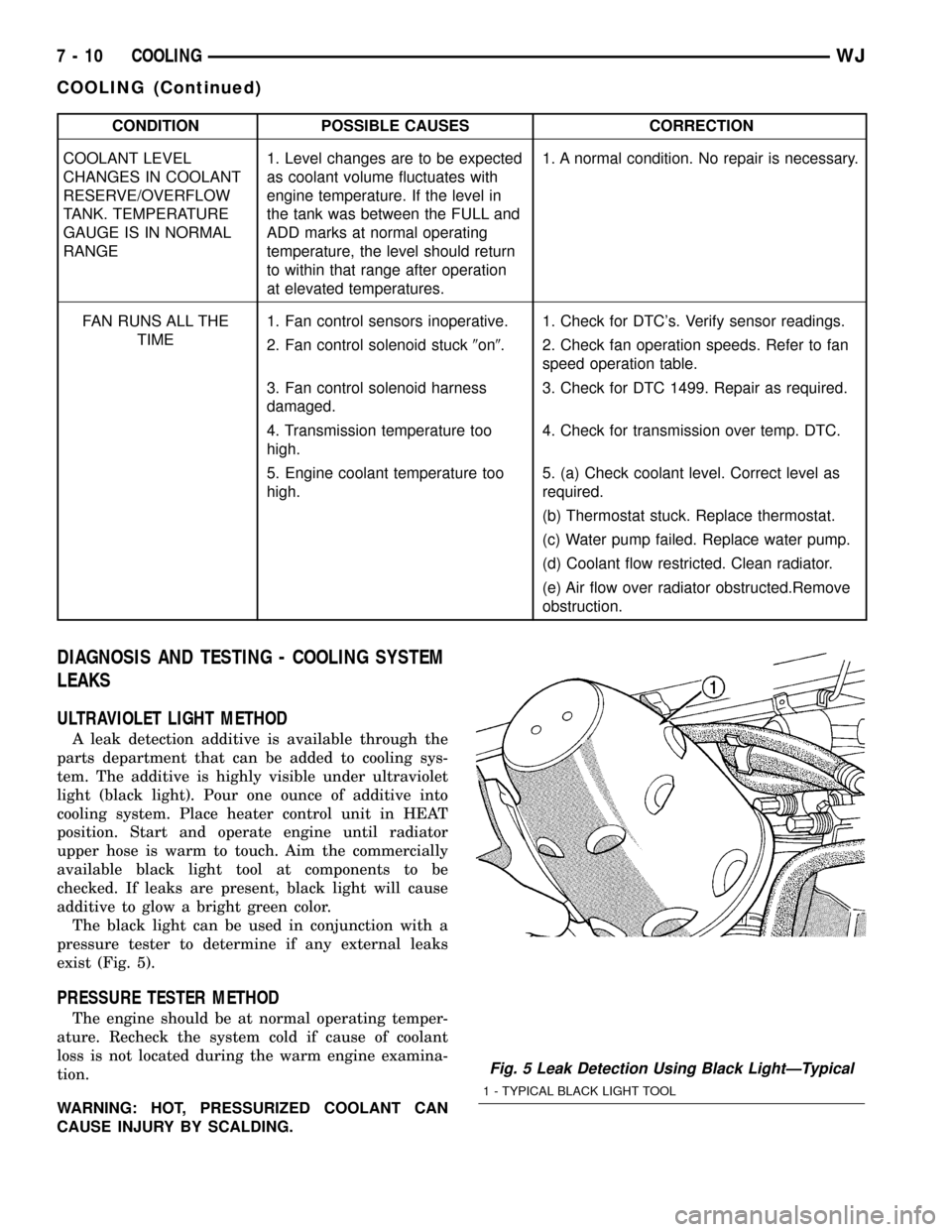
The black light can be used in conjunction with a
pressure tester to determine if any external leaks
exist (Fig. 5).
PRESSURE TESTER METHOD
The engine should be at normal operating temper-
ature. Recheck the system cold if cause of coolant
loss is not located during the warm engine examina-
tion.
WARNING: HOT, PRESSURIZED COOLANT CAN
CAUSE INJURY BY SCALDING.
Fig. 5 Leak Detection Using Black LightÐTypical
1 - TYPICAL BLACK LIGHT TOOL
7 - 10 COOLINGWJ
COOLING (Continued)
Page 258 of 2199

(2) Insert block heater assembly with element loop
pointing at twelve o'clock (Fig. 19).
(3) With block heater fully seated, tighten center
screw to 2 N´m (17 in. lbs.) torque.
(4) Refill cooling system (Refer to 7 - COOLING -
STANDARD PROCEDURE).
(5) Start and warm the engine. Check for leaks.
ENGINE COOLANT TEMP
SENSOR
DESCRIPTION
The Engine Coolant Temperature (ECT) sensor is
used to sense engine coolant temperature. The sensor
protrudes into an engine water jacket.
The ECT sensor is a two-wire Negative Thermal
Coefficient (NTC) sensor. Meaning, as engine coolant
temperature increases, resistance (voltage) in the
sensor decreases. As temperature decreases, resis-
tance (voltage) in the sensor increases.
OPERATION
At key-on, the Powertrain Control Module (PCM)
sends out a regulated 5 volt signal to the ECT sensor.
The PCM then monitors the signal as it passes
through the ECT sensor to the sensor ground (sensor
return).
When the engine is cold, the PCM will operate in
Open Loop cycle. It will demand slightly richer air-
fuel mixtures and higher idle speeds. This is done
until normal operating temperatures are reached.
The PCM uses inputs from the ECT sensor for the
following calculations:
²for engine coolant temperature gauge operation
through CCD or PCI (J1850) communications
²Injector pulse-width
²Spark-advance curves
²ASD relay shut-down times
²Idle Air Control (IAC) motor key-on steps
²Pulse-width prime-shot during cranking
²O2 sensor closed loop times
²Purge solenoid on/off times
²EGR solenoid on/off times (if equipped)
²Leak Detection Pump operation (if equipped)
²Radiator fan relay on/off times (if equipped)
²Target idle speed
REMOVAL
REMOVALÐ4.0L ENGINE
WARNING: HOT, PRESSURIZED COOLANT CAN
CAUSE INJURY BY SCALDING. COOLING SYSTEM
MUST BE PARTIALLY DRAINED BEFORE REMOV-
ING THE ENGINE COOLANT TEMPERATURE (ECT)
SENSOR. REFER TO GROUP 7, COOLING.
(1) Partially drain cooling system. (Refer to 7 -
COOLING - STANDARD PROCEDURE).
Fig. 18 Drain Plug
1 - COOLANT TEMPERATURE SENSOR
2 - BLOCK DRAIN PLUG
Fig. 19 Engine Block Heater
1 - ENGINE BLOCK HEATER
WJENGINE 7 - 35
ENGINE BLOCK HEATER (Continued)
Page 324 of 2199

DESCRIPTION - POWER GROUNDS
The Powertrain Control Module (PCM) has 2 main
grounds. Both of these grounds are referred to as
power grounds. All of the high-current, noisy, electri-
cal devices are connected to these grounds as well as
all of the sensor returns. The sensor return comes
into the sensor return circuit, passes through noise
suppression, and is then connected to the power
ground.
The power ground is used to control ground cir-
cuits for the following PCM loads:
²Generator field winding
²Fuel injectors
²Ignition coil(s)
²Certain relays/solenoids
²Certain sensors
DESCRIPTION - SENSOR RETURN
The Sensor Return circuits are internal to the Pow-
ertrain Control Module (PCM).
Sensor Return provides a low±noise ground refer-
ence for all engine control system sensors. Refer to
Power Grounds for more information.
OPERATION
OPERATION - PCM
(1) Also refer to Modes of Operation.
The PCM operates the fuel system. The PCM is a
pre-programmed, triple microprocessor digital com-
puter. It regulates ignition timing, air-fuel ratio,
emission control devices, charging system, certain
transmission features, speed control, air conditioning
compressor clutch engagement and idle speed. The
PCM can adapt its programming to meet changing
operating conditions.
The PCM receives input signals from various
switches and sensors. Based on these inputs, the
PCM regulates various engine and vehicle operations
through different system components. These compo-
nents are referred to as Powertrain Control Module
(PCM) Outputs. The sensors and switches that pro-
vide inputs to the PCM are considered Powertrain
Control Module (PCM) Inputs.
The PCM adjusts ignition timing based upon
inputs it receives from sensors that react to: engine
rpm, manifold absolute pressure, engine coolant tem-
perature, throttle position, transmission gear selec-
tion (automatic transmission), vehicle speed and the
brake switch.
The PCM adjusts idle speed based on inputs it
receives from sensors that react to: throttle position,
vehicle speed, transmission gear selection, engine
coolant temperature and from inputs it receives from
the air conditioning clutch switch and brake switch.Based on inputs that it receives, the PCM adjusts
ignition coil dwell. The PCM also adjusts the gener-
ator charge rate through control of the generator
field and provides speed control operation.
NOTE: PCM Inputs:
²A/C request
²Auto shutdown (ASD) sense
²Battery temperature
²Battery voltage
²Brake switch
²J1850 bus circuits
²Camshaft position sensor signal
²Crankshaft position sensor
²Data link connections for DRB scan tool
²Engine coolant temperature sensor
²Five volts (primary)
²Five volts (secondary)
²Fuel level
²Generator (battery voltage) output
²Ignition circuit sense (ignition switch in on/off/
crank/run position)
²Intake manifold air temperature sensor
²Leak detection pump (switch) sense (if equipped)
²Manifold absolute pressure (MAP) sensor
²Oil pressure
²Overdrive/override switch
²Oxygen sensors
²Park/neutral switch (auto. trans. only)
²Power ground
²Sensor return
²Signal ground
²Speed control multiplexed single wire input
²Throttle position sensor
²Transmission governor pressure sensor
²Transmission temperature sensor
²Vehicle speed (from ABS module)
NOTE: PCM Outputs:
²A/C clutch relay
²Auto shutdown (ASD) relay
²J1850 (+/-) circuits for: speedometer, voltmeter,
fuel gauge, oil pressure gauge/lamp, engine temp.
gauge and speed control warn. lamp
²Data link connection for DRBIIItscan tool
²EGR valve control solenoid (if equipped)
²EVAP canister purge solenoid
²Fuel injectors
²Fuel pump relay
²Generator field driver (-)
²Generator field driver (+)
²Generator lamp (if equipped)
²Idle air control (IAC) motor
²Ignition coil
²Leak detection pump
WJELECTRONIC CONTROL MODULES 8E - 15
POWERTRAIN CONTROL MODULE (Continued)
Page 357 of 2199

SPECIAL TOOLS
BATTERY TEMPERATURE
SENSOR
DESCRIPTION
The Battery Temperature Sensor (BTS) is attached
to the battery tray located under the battery.
OPERATION
The BTS is used to determine the battery temper-
ature and control battery charging rate. This temper-
ature data, along with data from monitored line
voltage, is used by the PCM to vary the battery
charging rate. System voltage will be higher at colder
temperatures and is gradually reduced at warmer
temperatures.
The PCM sends 5 volts to the sensor and is
grounded through the sensor return line. As temper-
ature increases, resistance in the sensor decreases
and the detection voltage at the PCM increases.The BTS is also used for OBD II diagnostics. Cer-
tain faults and OBD II monitors are either enabled
or disabled, depending upon BTS input (for example,
disable purge and enable Leak Detection Pump
(LDP) and O2 sensor heater tests). Most OBD II
monitors are disabled below 20 degrees F.
REMOVAL
The battery temperature sensor is located under
the vehicle battery (Fig. 1) and is attached to a
mounting hole on the battery tray.
The battery temperature sensor is located under
the vehicle battery (Fig. 1) and is attached to a
mounting hole on the battery tray.
(1) Remove battery. Refer to Group 8A, Battery for
procedures.
(2) Remove battery tray.
(3) Pull sensor up from battery tray and discon-
nect engine wire harness.
(4) Remove sensor from battery tray.
INSTALLATION
The battery temperature sensor is located under
the vehicle battery (Fig. 1) and is attached to a
mounting hole on the battery tray.
(1) Position sensor into mounting hole and attach
wiring harness.
(2) Press sensor into top of battery tray.
(3) Install battery. Refer to Group 8A, Battery for
procedures.
GENERATOR DECOUPLER TOOL #8433
GENERATOR DECOUPLER TOOL #8823
Fig. 1 Battery Temperature Sensor Location
1 - BATTERY TEMPERATURE SENSOR
2 - ENGINE WIRE HARNESS
3 - BATTERY TRAY
8F - 26 CHARGINGWJ
CHARGING (Continued)
Page 672 of 2199

8W-02 COMPONENT INDEX
Component Page
A/C Compressor Clutch................. 8W-42
A/C Pressure Transducer................ 8W-42
Accelerator Pedal Position Sensor......... 8W-30
Accessory Delay Relay.................. 8W-64
Adjustable Pedals..................... 8W-30
Airbags............................. 8W-43
Ambient Temperature Sensor............ 8W-45
Antennas............................ 8W-47
Ash Receiver Lamp.................... 8W-44
Auto Shut Down Relay................. 8W-30
Automatic Day/Night Mirror............. 8W-49
Automatic Headlamp Light Sensor/VTSS
LED.............................. 8W-39
Automatic Zone Control Module.......... 8W-42
Back-Up Lamp Relay................... 8W-51
Battery Temperature Sensor............. 8W-30
Battery............................. 8W-20
Blend Door Motor/Actuator.............. 8W-42
Blower Motor......................... 8W-42
Body Control Module................... 8W-45
Boost Pressure Sensor.................. 8W-30
Brake Lamp Switch.................... 8W-33
Camshaft Position Sensor............... 8W-30
Capacitors........................... 8W-30
Cargo Lamp.......................... 8W-44
Center High Mounted Stop Lamp......... 8W-51
Cigar Lighter......................... 8W-41
Circuit Breakers...................... 8W-12
Clockspring.................. 8W-33, 41, 43, 47
Coil On Plugs......................... 8W-30
Coil Rail............................. 8W-30
Combination Flasher................... 8W-52
Compact Disc Changer.................. 8W-47
Controller Antilock Brake............... 8W-35
Coolant Level Sensor................... 8W-45
Courtesy Lamps....................... 8W-44
Crankcase Heater..................... 8W-30
Crankshaft Position Sensor.............. 8W-30
Cylinder Lock Switches................. 8W-61
Data Link Connector................... 8W-18
Diagnostic Junction Port................ 8W-18
EGR Solenoid......................... 8W-30
Electric Brake........................ 8W-54
Electronic Speed Control Servo........... 8W-33
Engine Control Module................. 8W-30
Engine Coolant Temperature Sensor...... 8W-30
Engine Oil Pressure Sensor.............. 8W-30
Engine Starter Motor................... 8W-21
EVAP/Purge Solenoid................... 8W-30
Fog Lamps........................ 8W-50, 51
Fuel Injectors......................... 8W-30
Fuel Pressure Sensor................... 8W-30Component Page
Fuel Pressure Solenoid................. 8W-30
Fuel Pump........................... 8W-30
Fuel Tank Module..................... 8W-30
Fuses............................ 8W-10, 12
Fusible Link....................... 8W-10, 20
Grounds............................. 8W-15
Generator......................... 8W-20, 30
Glove Box Lamp...................... 8W-44
Glow Plugs........................... 8W-30
Headlamp Leveling Motor............... 8W-50
Heated Seats......................... 8W-63
High Beam Headlamps................. 8W-50
Hood Ajar Switch...................... 8W-39
Horns............................... 8W-41
Hydraulic Cooling Module............ 8W-30, 42
Idle Air Control Motor.................. 8W-30
Ignition Switch....................... 8W-10
Impact Sensors....................... 8W-43
Input Speed Sensor.................... 8W-31
Instrument Cluster.................... 8W-40
Intake Air Temperature Sensor........... 8W-30
Intake Port Swirl Actuator.............. 8W-30
Intrusion Transceiver Module............ 8W-49
Junction Block........................ 8W-12
Knock Sensor......................... 8W-30
Lamp Assemblies................... 8W-51, 52
Leak Detection Pump.................. 8W-30
License Lamps........................ 8W-51
Liftgate............................. 8W-61
Line Pressure Sensor................... 8W-31
Low Beam Headlamps.................. 8W-50
Low Beam Relay...................... 8W-50
Low Beam/Daytime Running Lamp Relay . . . 8W-50
Lumbar Motor........................ 8W-63
Lumbar Switch....................... 8W-63
Manifold Absolute Pressure Sensor........ 8W-30
Manual Temperature Control............. 8W-42
Mass Air Flow Sensor.................. 8W-30
Memory Set Switch................. 8W-62, 63
Mode Door Motor/Actuator............... 8W-42
Multi-Function Switch............... 8W-50, 53
Output Speed Sensor................... 8W-31
Overhead Map/Courtesy Lamp........... 8W-44
Oxygen Sensors....................... 8W-30
Park Brake Switch..................... 8W-40
Park Lamp........................... 8W-50
Park/Neutral Position Switch............ 8W-31
Park/Turn Signal Lamps................ 8W-50
Power Amplifier....................... 8W-47
Power Connector...................... 8W-41
Power Distribution Center............... 8W-10
Power Mirrors........................ 8W-62
WJ8W-02 COMPONENT INDEX 8W - 02 - 1
Page 782 of 2199

8W-30 FUEL/IGNITION SYSTEM
Component Page
A/C Compressor Clutch Relay . . . 8W-30-23, 35, 39, 41, 42
A/C Pressure Transducer........ 8W-30-21, 42, 45, 31
Accelerator Pedal Position Sensor........ 8W-30-37, 48
Adjustable Pedals Module................ 8W-30-33
Adjustable Pedals Motor/Sensor Assembly.... 8W-30-33
Adjustable Pedals Switch................ 8W-30-33
Auto Shut Down Relay...... 8W-30-8, 9, 12, 24, 25, 26,
27, 28, 29, 30, 35, 39, 41
Battery Temperature Sensor.......... 8W-30-2, 11, 50
Body Control Module................... 8W-30-46
Boost Pressure Sensor.................. 8W-30-45
Brake Lamp Switch.............. 8W-30-4, 5, 32, 51
Camshaft Position Sensor........ 8W-30-18, 19, 20, 49
Capacitor........................... 8W-30-12
Capacitor No. 1....................... 8W-30-16
Capacitor No. 2....................... 8W-30-17
Clockspring...................... 8W-30-4, 5, 38
Coil On Plug No. 1.................... 8W-30-17
Coil On Plug No. 2.................... 8W-30-16
Coil On Plug No. 3.................... 8W-30-17
Coil On Plug No. 4.................... 8W-30-16
Coil On Plug No. 5.................... 8W-30-17
Coil On Plug No. 6.................... 8W-30-16
Coil On Plug No. 7.................... 8W-30-17
Coil On Plug No. 8.................... 8W-30-16
Coil Rail............................ 8W-30-12
Controller Antilock Brake........... 8W-30-2, 36, 51
Crankcase Heater..................... 8W-30-35
Crankshaft Position Sensor....... 8W-30-18, 19, 20, 49
Data Link Connector............... 8W-30-6, 7, 46
Diagnostic Junction Port.......... 8W-30-6, 7, 33, 46
EGR Solenoid........................ 8W-30-50
Electronic Speed Control Servo........... 8W-30-4, 5
Engine Control Module.... 8W-30-34, 35, 36, 37, 38, 39,
40, 41, 42, 43, 44, 45,
46, 47, 48, 49, 50, 51
Engine Coolant Temperature Sensor . . . 8W-30-21, 22, 47
Engine Oil Pressure Sensor......... 8W-30-21, 22, 45
Engine Starter Motor Relay......... 8W-30-18, 19, 39
EVAP/Purge Solenoid.................. 8W-30-4, 5
Fuel Injector No. 1............... 8W-30-13, 15, 44
Fuel Injector No. 2............... 8W-30-13, 14, 44
Fuel Injector No. 3............... 8W-30-13, 15, 44
Fuel Injector No. 4............... 8W-30-13, 14, 44
Fuel Injector No. 5............... 8W-30-13, 15, 44
Fuel Injector No. 6.................. 8W-30-13, 14
Fuel Injector No. 7..................... 8W-30-15
Fuel Injector No. 8..................... 8W-30-14
Fuel Pressure Sensor................... 8W-30-37
Fuel Pressure Solenoid.................. 8W-30-47
Fuel Pump Module.................... 8W-30-10
Fuel Pump Relay.................. 8W-30-8, 9, 10
Fuel Tank Module..................... 8W-30-45
Fuse 6........................... 8W-30-8, 42
Fuse 10............................ 8W-30-33
Fuse 11............................ 8W-30-43
Fuse 12......................... 8W-30-8, 9, 40
Fuse 13............................ 8W-30-41
Fuse 16 . . 8W-30-24, 25, 26, 27, 28, 29, 30, 35, 37, 39, 41
Component Page
Fuse 19............................. 8W-30-9
Fuse 21......................... 8W-30-4, 5, 32
Fuse 22............................ 8W-30-34
Fuse 23............................ 8W-30-39
Fuse 24............................. 8W-30-9
Fuse 26..................... 8W-30-8, 12, 41, 47
Fuse 31............................ 8W-30-39
G103....................... 8W-30-8, 34, 39, 46
G104......................... 8W-30-26, 27, 30
G105........................... 8W-30-35, 39
G108........................... 8W-30-23, 43
G123.............................. 8W-30-50
G300............................ 8W-30-4, 33
G301............................ 8W-30-5, 10
Generator...................... 8W-30-3, 23, 35
Glow Plug No. 1...................... 8W-30-42
Glow Plug No. 2...................... 8W-30-43
Glow Plug No. 3...................... 8W-30-42
Glow Plug No. 4...................... 8W-30-43
Glow Plug No. 5...................... 8W-30-42
Glow Plug Relay No. 1............. 8W-30-35, 42, 43
Glow Plug Relay No. 2............. 8W-30-35, 42, 43
Hydraulic Cooling Module . . . 8W-30-3, 24, 25, 30, 31, 43
Idle Air Control Motor.................. 8W-30-20
Intake Air Temperature Sensor....... 8W-30-21, 22, 38
Intake Port Swirl Actuator............... 8W-30-39
Junction Block......... 8W-30-4, 5, 8, 9, 32, 33, 39, 40
Knock Sensor........................ 8W-30-11
Leak Detection Pump................... 8W-30-23
Manifold Absolute Pressure Sensor.... 8W-30-20, 21, 22
Mass Air Flow Sensor.................. 8W-30-37
Output Speed Sensor.................... 8W-30-2
Oxygen Sensor 1/1 Upstream...... 8W-30-25, 26, 28, 29
Oxygen Sensor 1/2 Downstream.... 8W-30-24, 25, 26, 30
Oxygen Sensor 2/1 Upstream........ 8W-30-27, 28, 29
Oxygen Sensor 2/2 Downstream...... 8W-30-24, 27, 30
Oxygen Sensor Downstream Relay . . 8W-30-24, 26, 27, 30
Park/Neutral Position Switch............. 8W-30-33
Power Distribution Center...... 8W-30-8, 9, 12, 24, 25,
26, 27, 28, 29, 30, 34, 35,
37, 39, 41, 42, 43, 47
Powertrain Control Module . . . 8W-30-2, 3, 4, 5, 6, 7, 8, 9,
10, 11, 12, 13, 14, 15, 16, 17,
18, 19, 20, 21, 22, 23, 24, 25,
26, 27, 28, 29, 30, 31, 32
Shifter Assembly............... 8W-30-2, 32, 38, 40
Speed Control Switch No. 1........... 8W-30-4, 5, 38
Speed Control Switch No. 2........... 8W-30-4, 5, 38
Throttle Position Sensor................. 8W-30-20
Transfer Case Position Sensor........... 8W-30-8, 51
Transmission Control
Module............. 8W-30-6, 7, 20, 23, 32, 36, 40
Transmission Control Relay.............. 8W-30-23
Transmission Solenoid................ 8W-30-3, 21
Transmission Solenoid/TRS Assembly....... 8W-30-33
Viscous/Cabin Heater................... 8W-30-39
Viscous/Cabin Heater Relay...... 8W-30-35, 39, 41, 42
Wastegate Solenoid.................... 8W-30-35
Water In Fuel Sensor................... 8W-30-50
WJ8W-30 FUEL/IGNITION SYSTEM 8W - 30 - 1
Page 1050 of 2199

Component Page
DRIVER SEAT BELT SWITCH........ 8W-80-74
DRIVER SIDE IMPACT SENSOR...... 8W-80-74
EGR SOLENOID (DIESEL)........... 8W-80-74
ELECTRIC BRAKE
(EXCEPT BUILT-UP-EXPORT)...... 8W-80-74
ELECTRONIC SPEED CONTROL
SERVO ......................... 8W-80-74
ENGINE CONTROL MODULE C1
(DIESEL)....................... 8W-80-75
ENGINE CONTROL MODULE C2
(DIESEL)....................... 8W-80-76
ENGINE COOLANT TEMPERATURE
SENSOR (DIESEL)................ 8W-80-77
ENGINE COOLANT TEMPERATURE
SENSOR (GAS)................... 8W-80-77
ENGINE OIL PRESSURE
SENSOR (DIESEL)................ 8W-80-77
ENGINE OIL PRESSURE
SENSOR (GAS)................... 8W-80-78
EVAP/PURGE SOLENOID (GAS)....... 8W-80-78
FRONT POWER OUTLET............ 8W-80-78
FRONT WASHER PUMP............. 8W-80-78
FRONT WIPER MOTOR............. 8W-80-78
FUEL INJECTOR NO. 1 (DIESEL)..... 8W-80-79
FUEL INJECTOR NO. 1 (GAS)........ 8W-80-79
FUEL INJECTOR NO. 2 (DIESEL)..... 8W-80-79
FUEL INJECTOR NO. 2 (GAS)........ 8W-80-79
FUEL INJECTOR NO. 3 (DIESEL)..... 8W-80-79
FUEL INJECTOR NO. 3 (GAS)........ 8W-80-80
FUEL INJECTOR NO. 4 (DIESEL)..... 8W-80-80
FUEL INJECTOR NO. 4 (GAS)........ 8W-80-80
FUEL INJECTOR NO. 5 (DIESEL)..... 8W-80-80
FUEL INJECTOR NO. 5 (GAS)........ 8W-80-81
FUEL INJECTOR NO. 6 (GAS)........ 8W-80-81
FUEL INJECTOR NO. 7 (4.7L)........ 8W-80-81
FUEL INJECTOR NO. 8 (4.7L)........ 8W-80-81
FUEL PRESSURE SENSOR (DIESEL) . . 8W-80-82
FUEL PRESSURE SOLENOID
(DIESEL)....................... 8W-80-82
FUEL PUMP MODULE (GAS)......... 8W-80-82
FUEL TANK MODULE (DIESEL)...... 8W-80-82
GENERATOR (DIESEL).............. 8W-80-82
GENERATOR (GAS)................. 8W-80-83
GLOVE BOX LAMP................. 8W-80-83
HEADLAMP LEVELING SWITCH
(BUILT-UP-EXPORT).............. 8W-80-83
HOOD AJAR SWITCH
(BUILT-UP-EXPORT).............. 8W-80-83
HORN NO. 1....................... 8W-80-83
HORN NO. 2....................... 8W-80-84
HYDRAULIC COOLING MODULE..... 8W-80-84
IDLE AIR CONTROL MOTOR......... 8W-80-84
IGNITION SWITCH C1.............. 8W-80-84
IGNITION SWITCH C2.............. 8W-80-84
INPUT SPEED SENSOR (4.7L)........ 8W-80-85Component Page
INSTRUMENT CLUSTER............ 8W-80-85
INTAKE AIR TEMPERATURE
SENSOR (DIESEL)................ 8W-80-85
INTAKE AIR TEMPERATURE
SENSOR (GAS)................... 8W-80-85
INTAKE PORT SWIRL ACTUATOR
(DIESEL)....................... 8W-80-86
INTRUSION TRANSCEIVER MODULE
(BUILT-UP-EXPORT).............. 8W-80-86
JUNCTION BLOCK BODY
CONTROL MODULE.............. 8W-80-86
JUNCTION BLOCK C1.............. 8W-80-87
JUNCTION BLOCK C2 (LHD)......... 8W-80-88
JUNCTION BLOCK C2 (RHD)......... 8W-80-89
JUNCTION BLOCK C3.............. 8W-80-90
JUNCTION BLOCK C4.............. 8W-80-91
JUNCTION BLOCK C5.............. 8W-80-91
KNOCK SENSOR................... 8W-80-91
LEAK DETECTION PUMP (EXCEPT
BUILT-UP-EXPORT)............... 8W-80-91
LEFT COURTESY LAMP............. 8W-80-91
LEFT DOOR HANDLE COURTESY
LAMP.......................... 8W-80-92
LEFT FOG LAMP................... 8W-80-92
LEFT FRONT DOOR SPEAKER....... 8W-80-92
LEFT FRONT IMPACT SENSOR....... 8W-80-92
LEFT FRONT PARK LAMP........... 8W-80-92
LEFT FRONT PARK/TURN SIGNAL LAMP
(EXCEPT BUILT-UP-EXPORT)...... 8W-80-93
LEFT FRONT SIDE MARKER LAMP
(EXCEPT BUILT-UP-EXPORT)...... 8W-80-93
LEFT FRONT TURN SIGNAL LAMP
(BUILT-UP-EXPORT).............. 8W-80-93
LEFT FRONT WHEEL SPEED
SENSOR........................ 8W-80-93
LEFT HEADLAMP LEVELING MOTOR
(BUILT-UP-EXPORT).............. 8W-80-94
LEFT HIGH BEAM HEADLAMP....... 8W-80-94
LEFT INSTRUMENT PANEL SPEAKER . 8W-80-94
LEFT LIFTGATE AJAR SWITCH....... 8W-80-94
LEFT LOW BEAM HEADLAMP....... 8W-80-94
LEFT MULTI-FUNCTION SWITCH.... 8W-80-95
LEFT REAR DOOR LOCK
MOTOR/AJAR SWITCH............ 8W-80-95
LEFT REAR DOOR SPEAKER......... 8W-80-95
LEFT REAR LAMP ASSEMBLY........ 8W-80-95
LEFT REAR WHEEL SPEED
SENSOR........................ 8W-80-96
LEFT REMOTE RADIO SWITCH...... 8W-80-96
LEFT SIDE REPEATER LAMP
(BUILT-UP-EXPORT).............. 8W-80-96
LEFT VISOR/VANITY LAMP.......... 8W-80-96
LICENSE LAMP NO. 1.............. 8W-80-96
LICENSE LAMP NO. 2.............. 8W-80-97
LIFTGATE FLIP-UP AJAR SWITCH.... 8W-80-97
WJ8W-80 CONNECTOR PIN-OUT 8W - 80 - 3
Page 1138 of 2199

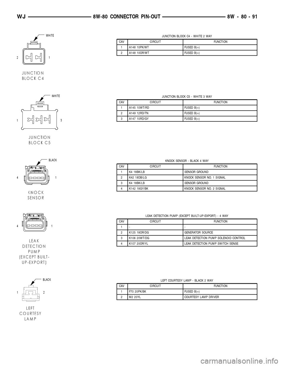
JUNCTION BLOCK C4 - WHITE 2 WAY
CAV CIRCUIT FUNCTION
1 A148 10PK/WT FUSED B(+)
2 A148 10OR/WT FUSED B(+)
JUNCTION BLOCK C5 - WHITE 3 WAY
CAV CIRCUIT FUNCTION
1 A145 10WT/RD FUSED B(+)
2 A149 12RD/TN FUSED B(+)
3 A147 10RD/GY FUSED B(+)
KNOCK SENSOR - BLACK 4 WAY
CAV CIRCUIT FUNCTION
1 K4 18BK/LB SENSOR GROUND
2 K42 18DB/LG KNOCK SENSOR NO. 1 SIGNAL
3 K4 18BK/LB SENSOR GROUND
4 K142 18GY/BK KNOCK SENSOR NO. 2 SIGNAL
LEAK DETECTION PUMP (EXCEPT BUILT-UP-EXPORT)-4WAY
CAV CIRCUIT FUNCTION
1- -
2 K125 18OR/DG GENERATOR SOURCE
3 K106 20WT/DG LEAK DETECTION PUMP SOLENOID CONTROL
4 K107 20OR/YL LEAK DETECTION PUMP SWITCH SENSE
LEFT COURTESY LAMP - BLACK 2 WAY
CAV CIRCUIT FUNCTION
1 F70 20PK/BK FUSED B(+)
2 M2 20YL COURTESY LAMP DRIVER
WJ8W-80 CONNECTOR PIN-OUT 8W - 80 - 91
Page 1157 of 2199

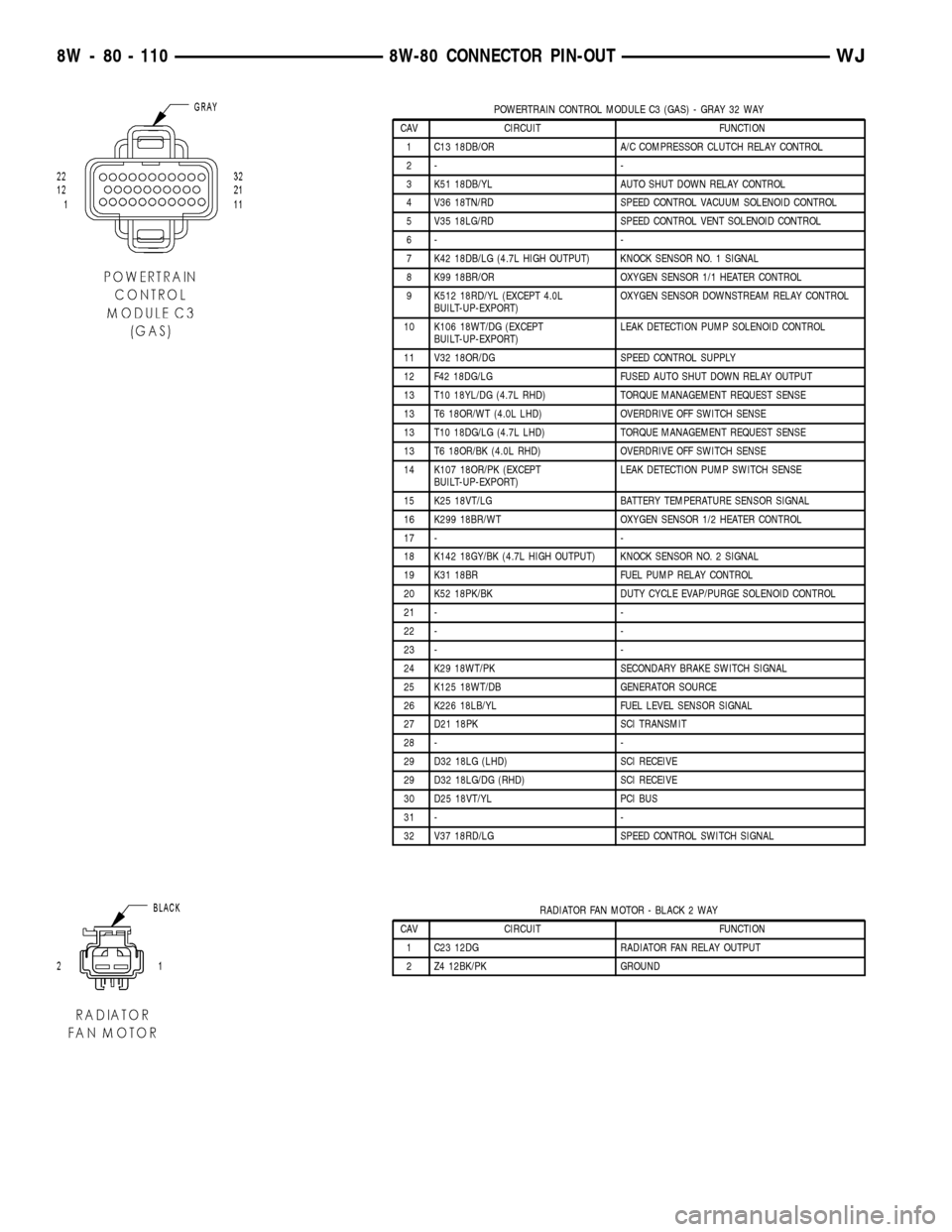
POWERTRAIN CONTROL MODULE C3 (GAS) - GRAY 32 WAY
CAV CIRCUIT FUNCTION
1 C13 18DB/OR A/C COMPRESSOR CLUTCH RELAY CONTROL
2- -
3 K51 18DB/YL AUTO SHUT DOWN RELAY CONTROL
4 V36 18TN/RD SPEED CONTROL VACUUM SOLENOID CONTROL
5 V35 18LG/RD SPEED CONTROL VENT SOLENOID CONTROL
6- -
7 K42 18DB/LG (4.7L HIGH OUTPUT) KNOCK SENSOR NO. 1 SIGNAL
8 K99 18BR/OR OXYGEN SENSOR 1/1 HEATER CONTROL
9 K512 18RD/YL (EXCEPT 4.0L
BUILT-UP-EXPORT)OXYGEN SENSOR DOWNSTREAM RELAY CONTROL
10 K106 18WT/DG (EXCEPT
BUILT-UP-EXPORT)LEAK DETECTION PUMP SOLENOID CONTROL
11 V32 18OR/DG SPEED CONTROL SUPPLY
12 F42 18DG/LG FUSED AUTO SHUT DOWN RELAY OUTPUT
13 T10 18YL/DG (4.7L RHD) TORQUE MANAGEMENT REQUEST SENSE
13 T6 18OR/WT (4.0L LHD) OVERDRIVE OFF SWITCH SENSE
13 T10 18DG/LG (4.7L LHD) TORQUE MANAGEMENT REQUEST SENSE
13 T6 18OR/BK (4.0L RHD) OVERDRIVE OFF SWITCH SENSE
14 K107 18OR/PK (EXCEPT
BUILT-UP-EXPORT)LEAK DETECTION PUMP SWITCH SENSE
15 K25 18VT/LG BATTERY TEMPERATURE SENSOR SIGNAL
16 K299 18BR/WT OXYGEN SENSOR 1/2 HEATER CONTROL
17 - -
18 K142 18GY/BK (4.7L HIGH OUTPUT) KNOCK SENSOR NO. 2 SIGNAL
19 K31 18BR FUEL PUMP RELAY CONTROL
20 K52 18PK/BK DUTY CYCLE EVAP/PURGE SOLENOID CONTROL
21 - -
22 - -
23 - -
24 K29 18WT/PK SECONDARY BRAKE SWITCH SIGNAL
25 K125 18WT/DB GENERATOR SOURCE
26 K226 18LB/YL FUEL LEVEL SENSOR SIGNAL
27 D21 18PK SCI TRANSMIT
28 - -
29 D32 18LG (LHD) SCI RECEIVE
29 D32 18LG/DG (RHD) SCI RECEIVE
30 D25 18VT/YL PCI BUS
31 - -
32 V37 18RD/LG SPEED CONTROL SWITCH SIGNAL
RADIATOR FAN MOTOR - BLACK 2 WAY
CAV CIRCUIT FUNCTION
1 C23 12DG RADIATOR FAN RELAY OUTPUT
2 Z4 12BK/PK GROUND
8W - 80 - 110 8W-80 CONNECTOR PIN-OUTWJ
Page 1181 of 2199

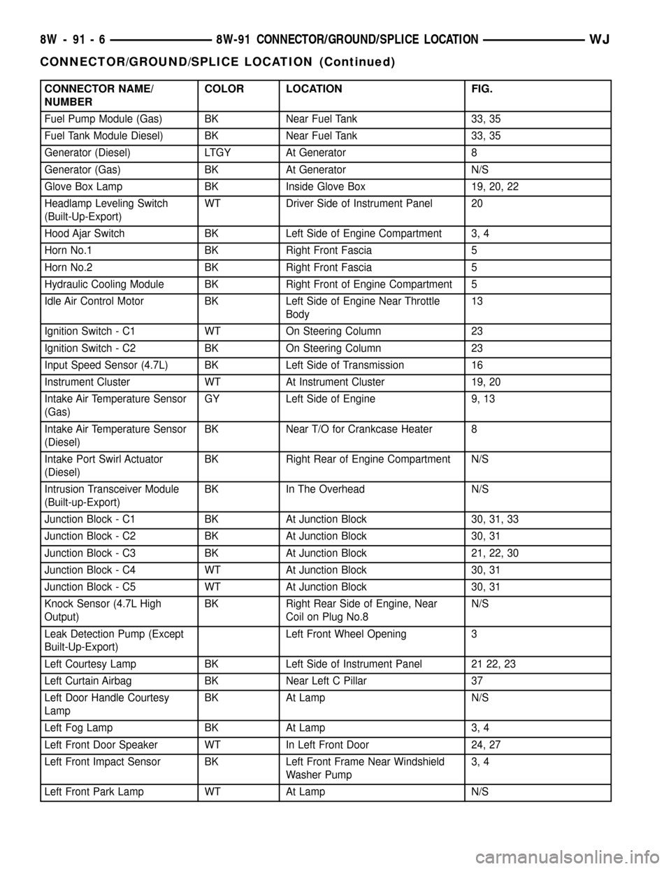
CONNECTOR NAME/
NUMBERCOLOR LOCATION FIG.
Fuel Pump Module (Gas) BK Near Fuel Tank 33, 35
Fuel Tank Module Diesel) BK Near Fuel Tank 33, 35
Generator (Diesel) LTGY At Generator 8
Generator (Gas) BK At Generator N/S
Glove Box Lamp BK Inside Glove Box 19, 20, 22
Headlamp Leveling Switch
(Built-Up-Export)WT Driver Side of Instrument Panel 20
Hood Ajar Switch BK Left Side of Engine Compartment 3, 4
Horn No.1 BK Right Front Fascia 5
Horn No.2 BK Right Front Fascia 5
Hydraulic Cooling Module BK Right Front of Engine Compartment 5
Idle Air Control Motor BK Left Side of Engine Near Throttle
Body13
Ignition Switch - C1 WT On Steering Column 23
Ignition Switch - C2 BK On Steering Column 23
Input Speed Sensor (4.7L) BK Left Side of Transmission 16
Instrument Cluster WT At Instrument Cluster 19, 20
Intake Air Temperature Sensor
(Gas)GY Left Side of Engine 9, 13
Intake Air Temperature Sensor
(Diesel)BK Near T/O for Crankcase Heater 8
Intake Port Swirl Actuator
(Diesel)BK Right Rear of Engine Compartment N/S
Intrusion Transceiver Module
(Built-up-Export)BK In The Overhead N/S
Junction Block - C1 BK At Junction Block 30, 31, 33
Junction Block - C2 BK At Junction Block 30, 31
Junction Block - C3 BK At Junction Block 21, 22, 30
Junction Block - C4 WT At Junction Block 30, 31
Junction Block - C5 WT At Junction Block 30, 31
Knock Sensor (4.7L High
Output)BK Right Rear Side of Engine, Near
Coil on Plug No.8N/S
Leak Detection Pump (Except
Built-Up-Export)Left Front Wheel Opening 3
Left Courtesy Lamp BK Left Side of Instrument Panel 21 22, 23
Left Curtain Airbag BK Near Left C Pillar 37
Left Door Handle Courtesy
LampBK At Lamp N/S
Left Fog Lamp BK At Lamp 3, 4
Left Front Door Speaker WT In Left Front Door 24, 27
Left Front Impact Sensor BK Left Front Frame Near Windshield
Washer Pump3, 4
Left Front Park Lamp WT At Lamp N/S
8W - 91 - 6 8W-91 CONNECTOR/GROUND/SPLICE LOCATIONWJ
CONNECTOR/GROUND/SPLICE LOCATION (Continued)