Shift to 4wd JEEP GRAND CHEROKEE 2002 WJ / 2.G Workshop Manual
[x] Cancel search | Manufacturer: JEEP, Model Year: 2002, Model line: GRAND CHEROKEE, Model: JEEP GRAND CHEROKEE 2002 WJ / 2.GPages: 2199, PDF Size: 76.01 MB
Page 65 of 2199
Condition Possible Causes Correction
Axle Noise 1. Insufficient lubricant. 1. Fill differential with the correct
fluid type and quantity.
2. Improper ring gear and pinion
adjustment.2. Check ring gear and pinion
contact pattern.
3. Unmatched ring gear and pinion. 3. Replace gears with a matched
ring gear and pinion.
4. Worn teeth on ring gear and/or
pinion.4. Replace ring gear and pinion.
5. Loose pinion bearings. 5. Adjust pinion bearing pre-load.
6. Loose differential bearings. 6. Adjust differential bearing
pre-load.
7. Mis-aligned or sprung ring gear. 7. Measure ring gear run-out.
Replace components as necessary.
8. Loose differential bearing cap
bolts.8. Inspect differential components
and replace as necessary. Ensure
that the bearing caps are torqued
tot he proper specification.
9. Housing not machined properly. 9. Replace housing.
VARI-LOKT
(1) Park the vehicle on a level surface or raise
vehicle on hoist so that the vehicle is level.
(2) Remove the axle fill plug.
(3) Verify that the axle fluid level is correct. The
fluid level is correct if the fluid is level with the bot-
tom of the fill hole.
(4) Shift the transfer case into the 4WD full-time
position.
(5) Drive the vehicle in a tight circle for 2 minutes
at 5mph to fully prime the pump.
(6) Block the tires opposite the axle to be tested to
prevent the vehicle from moving.
(7) Shift the transfer case into the 4WD Low posi-
tion and the transmission into the Park position.
(8) Raise both the wheels of the axle to be tested
off of the ground.
(9) Rotate the left wheel by hand at a minimum of
one revolution per second while an assistant rotates
the right wheel in the opposite direction.
(10) The left wheel should spin freely at first and
then increase in resistance within 5 revolutions until
the wheels cannot be continuously rotated in opposite
directions.
(11) The Vari-loktdifferential has engaged prop-
erly if the wheels cannot be rotated in opposite direc-
tions for a moment. After the wheels stop rotating for
a moment, the fluid pressure will drop in the differ-
ential and the wheels begin to rotate once again.
(12) If the system does not operate properly,
replace the Vari-loktdifferential.
REMOVAL
(1) Raise and support the vehicle.
(2) Position a suitable lifting device under the
axle.
(3) Secure axle to lift.
(4) Remove the wheels and tires.
(5) Remove the brake calipers and rotors (Refer to
5 - BRAKES/HYDRAULIC/MECHANICAL/ROTORS
- REMOVAL) from the axle.
(6) Disconnect the wheel sensor wiring harness
from the vehicle wiring harness.
(7) Disconnect the vent hose from the axle shaft
tube.
(8) Mark propeller shaft and yoke/pinion flange for
installation alignment reference.
(9) Remove propeller shaft.
(10) Disconnect stabilizer bar links at the axle.
(11) Disconnect shock absorbers from axle brack-
ets.
(12) Disconnect track bar.
(13) Disconnect the tie rod and drag link from the
steering knuckle.
(14) Disconnect the steering damper from the axle
bracket.
(15) Disconnect the upper and lower suspension
arms from the axle brackets.
(16) Lower the lifting device enough to remove the
axle. The coil springs will drop with the axle.
(17) Remove the coil springs from the axle.
3 - 20 FRONT AXLE - 186FBIWJ
FRONT AXLE - 186FBI (Continued)
Page 100 of 2199
Condition Possible Causes Correction
Axle Noise 1. Insufficient lubricant. 1. Fill differential with the correct
fluid type and quantity.
2. Improper ring gear and pinion
adjustment.2. Check ring gear and pinion
contact pattern.
3. Unmatched ring gear and pinion. 3. Replace gears with a matched
ring gear and pinion.
4. Worn teeth on ring gear and/or
pinion.4. Replace ring gear and pinion.
5. Loose pinion bearings. 5. Adjust pinion bearing pre-load.
6. Loose differential bearings. 6. Adjust differential bearing
pre-load.
7. Mis-aligned or sprung ring gear. 7. Measure ring gear run-out.
Replace components as necessary.
8. Loose differential bearing cap
bolts.8. Inspect differential components
and replace as necessary. Ensure
that the bearing caps are torqued
tot he proper specification.
9. Housing not machined properly. 9. Replace housing.
VARI-LOKT
(1) Park the vehicle on a level surface or raise
vehicle on hoist so that the vehicle is level.
(2) Remove the axle fill plug.
(3) Verify that the axle fluid level is correct. The
fluid level is correct if the fluid is level with the bot-
tom of the fill hole.
(4) Shift the transfer case into the 4WD full-time
position.
(5) Drive the vehicle in a tight circle for 2 minutes
at 5mph to fully prime the pump.
(6) Block the tires opposite the axle to be tested to
prevent the vehicle from moving.
(7) Shift the transfer case into the 4WD Low posi-
tion and the transmission into the Park position.
(8) Raise both the wheels of the axle to be tested
off of the ground.
(9) Rotate the left wheel by hand at a minimum of
one revolution per second while an assistant rotates
the right wheel in the opposite direction.
(10) The left wheel should spin freely at first and
then increase in resistance within 5 revolutions until
the wheels cannot be continuously rotated in opposite
directions.
(11) The Vari-loktdifferential has engaged prop-
erly if the wheels cannot be rotated in opposite direc-tions for a moment. After the wheels stop rotating for
a moment, the fluid pressure will drop in the differ-
ential and the wheels begin to rotate once again.
(12) If the system does not operate properly,
replace the Vari-loktdifferential.
REMOVAL
(1) Raise and support the vehicle.
(2) Position a lifting device under the axle and
secure axle.
(3) Remove the wheels and tires.
(4) Remove brake calipers and rotors.
(5) Disconnect parking brake cables from brackets
and lever.
(6) Remove wheel speed sensors.
(7) Remove brake hose at the axle junction block.
Do not disconnect the brake hydraulic lines at the
calipers.
(8) Disconnect the vent hose from the axle shaft
tube.
(9) Mark propeller shaft and yokes for installation
reference.
(10) Remove propeller shaft.
(11) Disconnect stabilizer bar links.
(12) Remove upper suspension arm rear axle ball
joint nut.
WJREAR AXLE - 198RBI 3 - 55
REAR AXLE - 198RBI (Continued)
Page 140 of 2199
Condition Possible Causes Correction
Gear Teeth Broke 1. Overloading. 1. Replace gears. Examine other
gears and bearings for possible
damage.
2. Erratic clutch operation. 2. Replace gears and examine the
remaining parts for damage. Avoid
erratic clutch operation.
3. Ice-spotted pavement. 3. Replace gears and examine
remaining parts for damage.
4. Improper adjustments. 4. Replace gears and examine
remaining parts for damage. Ensure
ring gear backlash is correct.
Axle Noise 1. Insufficient lubricant. 1. Fill differential with the correct
fluid type and quantity.
2. Improper ring gear and pinion
adjustment.2. Check ring gear and pinion
contact pattern.
3. Unmatched ring gear and pinion. 3. Replace gears with a matched
ring gear and pinion.
4. Worn teeth on ring gear and/or
pinion.4. Replace ring gear and pinion.
5. Loose pinion bearings. 5. Adjust pinion bearing pre-load.
6. Loose differential bearings. 6. Adjust differential bearing
pre-load.
7. Mis-aligned or sprung ring gear. 7. Measure ring gear run-out.
Replace components as necessary.
8. Loose differential bearing cap
bolts.8. Inspect differential components
and replace as necessary. Ensure
that the bearing caps are torqued
tot he proper specification.
9. Housing not machined properly. 9. Replace housing.
VARI-LOKT
(1) Park the vehicle on a level surface or raise
vehicle on hoist so that the vehicle is level.
(2) Remove the axle fill plug.
(3) Verify that the axle fluid level is correct. The
fluid level is correct if the fluid is level with the bot-
tom of the fill hole.
(4) Shift the transfer case into the 4WD full-time
position.
(5) Drive the vehicle in a tight circle for 2 minutes
at 5mph to fully prime the pump.
(6) Block the tires opposite the axle to be tested to
prevent the vehicle from moving.
(7) Shift the transfer case into the 4WD Low posi-
tion and the transmission into the Park position.
(8) Raise both the wheels of the axle to be tested
off of the ground.(9) Rotate the left wheel by hand at a minimum of
one revolution per second while an assistant rotates
the right wheel in the opposite direction.
(10) The left wheel should spin freely at first and
then increase in resistance within 5 revolutions until
the wheels cannot be continuously rotated in opposite
directions.
(11) The Vari-loktdifferential has engaged prop-
erly if the wheels cannot be rotated in opposite direc-
tions for a moment. After the wheels stop rotating for
a moment, the fluid pressure will drop in the differ-
ential and the wheels begin to rotate once again.
(12) If the system does not operate properly,
replace the Vari-loktdifferential.
REMOVAL
(1) Raise and support the vehicle.
(2) Position a lifting device under the axle and
secure axle.
WJREAR AXLE - 226RBA 3 - 95
REAR AXLE - 226RBA (Continued)
Page 1836 of 2199
CONDITION POSSIBLE CAUSE CORRECTION
NOISY INÐOR JUMPS OUT OF
4WD LOW RANGE1. Transfer case not completely
engaged in 4WD LOW (possibly
from shift to 4L while rolling)1. Stop vehicle, shift transfer case
to neutral, then shift back to 4WD
LOW
2. Shift linkage loose, binding, or is
misadjusted2. Tighten, lubricate, or repair
linkage as necessary. Adjust linkage
if necessary
3. Range fork cracked, inserts
worn, or fork is binding on shift rail3. Disassemble unit and repair as
necessary
4. Annulus gear or lockplate worn
or damaged4. Disassemble unit and repair as
necessary
LUBRICANT LEAKING FROM
OUTPUT SHAFT SEALS OR FROM
VENT1. Transfer case over filled 1. Drain to correct level
2. Vent closed or restricted 2. Clear or replace vent if necessary
3. Output shaft seals damaged or
installed correctly3. Replace seals. Be sure seal lip
faces interior of case when installed.
Also be sure yoke seal surfaces are
not scored or nicked. Remove
scores and nicks with fine
sandpaper or replace yoke(s) if
necessary.
REMOVAL
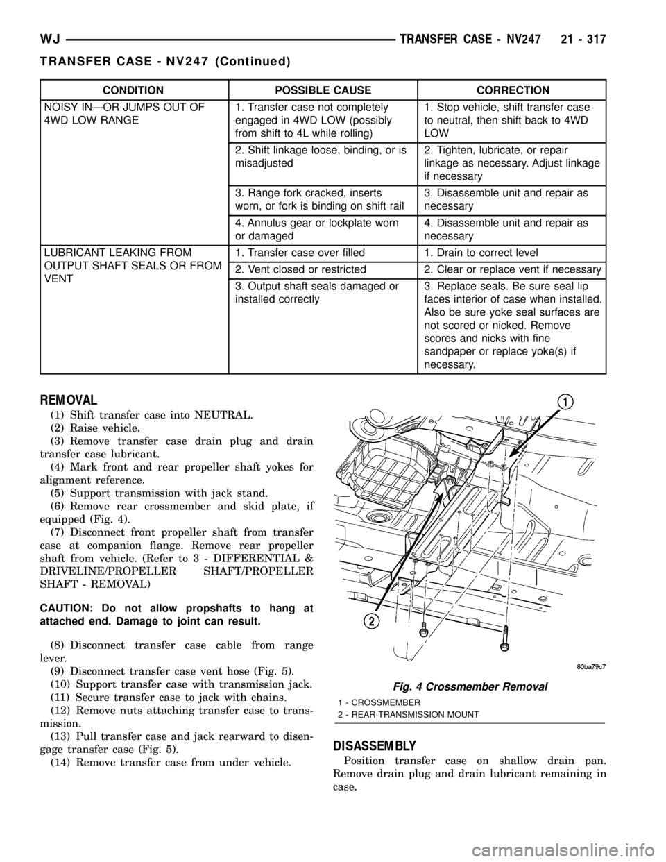
(1) Shift transfer case into NEUTRAL.
(2) Raise vehicle.
(3) Remove transfer case drain plug and drain
transfer case lubricant.
(4) Mark front and rear propeller shaft yokes for
alignment reference.
(5) Support transmission with jack stand.
(6) Remove rear crossmember and skid plate, if
equipped (Fig. 4).
(7) Disconnect front propeller shaft from transfer
case at companion flange. Remove rear propeller
shaft from vehicle. (Refer to 3 - DIFFERENTIAL &
DRIVELINE/PROPELLER SHAFT/PROPELLER
SHAFT - REMOVAL)
CAUTION: Do not allow propshafts to hang at
attached end. Damage to joint can result.
(8) Disconnect transfer case cable from range
lever.
(9) Disconnect transfer case vent hose (Fig. 5).
(10) Support transfer case with transmission jack.
(11) Secure transfer case to jack with chains.
(12) Remove nuts attaching transfer case to trans-
mission.
(13) Pull transfer case and jack rearward to disen-
gage transfer case (Fig. 5).
(14) Remove transfer case from under vehicle.
DISASSEMBLY
Position transfer case on shallow drain pan.
Remove drain plug and drain lubricant remaining in
case.
Fig. 4 Crossmember Removal
1 - CROSSMEMBER
2 - REAR TRANSMISSION MOUNT
WJTRANSFER CASE - NV247 21 - 317
TRANSFER CASE - NV247 (Continued)
Page 2165 of 2199
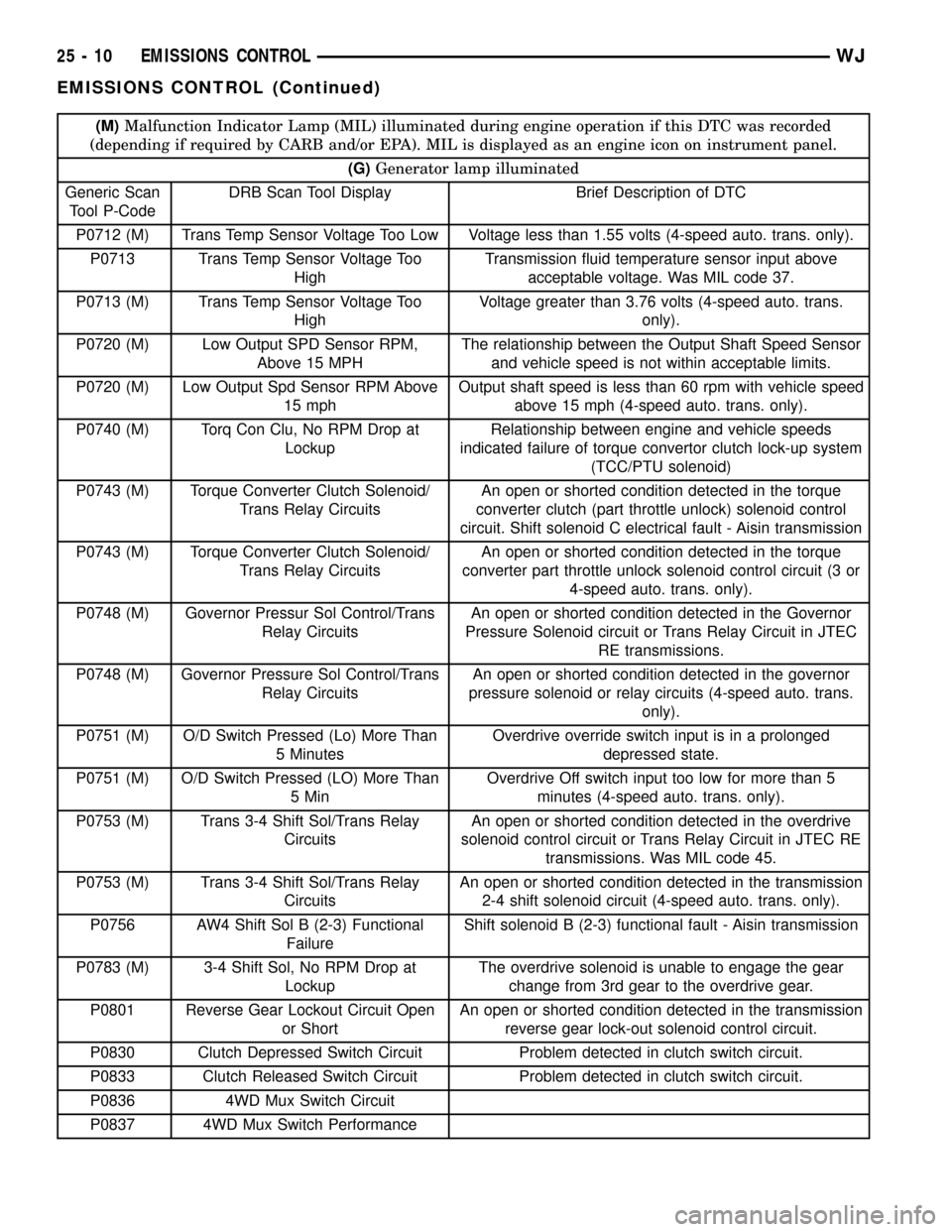
(M)Malfunction Indicator Lamp (MIL) illuminated during engine operation if this DTC was recorded
(depending if required by CARB and/or EPA). MIL is displayed as an engine icon on instrument panel.
(G)Generator lamp illuminated
Generic Scan
Tool P-CodeDRB Scan Tool Display Brief Description of DTC
P0712 (M) Trans Temp Sensor Voltage Too Low Voltage less than 1.55 volts (4-speed auto. trans. only).
P0713 Trans Temp Sensor Voltage Too
HighTransmission fluid temperature sensor input above
acceptable voltage. Was MIL code 37.
P0713 (M) Trans Temp Sensor Voltage Too
HighVoltage greater than 3.76 volts (4-speed auto. trans.
only).
P0720 (M) Low Output SPD Sensor RPM,
Above 15 MPHThe relationship between the Output Shaft Speed Sensor
and vehicle speed is not within acceptable limits.
P0720 (M) Low Output Spd Sensor RPM Above
15 mphOutput shaft speed is less than 60 rpm with vehicle speed
above 15 mph (4-speed auto. trans. only).
P0740 (M) Torq Con Clu, No RPM Drop at
LockupRelationship between engine and vehicle speeds
indicated failure of torque convertor clutch lock-up system
(TCC/PTU solenoid)
P0743 (M) Torque Converter Clutch Solenoid/
Trans Relay CircuitsAn open or shorted condition detected in the torque
converter clutch (part throttle unlock) solenoid control
circuit. Shift solenoid C electrical fault - Aisin transmission
P0743 (M) Torque Converter Clutch Solenoid/
Trans Relay CircuitsAn open or shorted condition detected in the torque
converter part throttle unlock solenoid control circuit (3 or
4-speed auto. trans. only).
P0748 (M) Governor Pressur Sol Control/Trans
Relay CircuitsAn open or shorted condition detected in the Governor
Pressure Solenoid circuit or Trans Relay Circuit in JTEC
RE transmissions.
P0748 (M) Governor Pressure Sol Control/Trans
Relay CircuitsAn open or shorted condition detected in the governor
pressure solenoid or relay circuits (4-speed auto. trans.
only).
P0751 (M) O/D Switch Pressed (Lo) More Than
5 MinutesOverdrive override switch input is in a prolonged
depressed state.
P0751 (M) O/D Switch Pressed (LO) More Than
5 MinOverdrive Off switch input too low for more than 5
minutes (4-speed auto. trans. only).
P0753 (M) Trans 3-4 Shift Sol/Trans Relay
CircuitsAn open or shorted condition detected in the overdrive
solenoid control circuit or Trans Relay Circuit in JTEC RE
transmissions. Was MIL code 45.
P0753 (M) Trans 3-4 Shift Sol/Trans Relay
CircuitsAn open or shorted condition detected in the transmission
2-4 shift solenoid circuit (4-speed auto. trans. only).
P0756 AW4 Shift Sol B (2-3) Functional
FailureShift solenoid B (2-3) functional fault - Aisin transmission
P0783 (M) 3-4 Shift Sol, No RPM Drop at
LockupThe overdrive solenoid is unable to engage the gear
change from 3rd gear to the overdrive gear.
P0801 Reverse Gear Lockout Circuit Open
or ShortAn open or shorted condition detected in the transmission
reverse gear lock-out solenoid control circuit.
P0830 Clutch Depressed Switch Circuit Problem detected in clutch switch circuit.
P0833 Clutch Released Switch Circuit Problem detected in clutch switch circuit.
P0836 4WD Mux Switch Circuit
P0837 4WD Mux Switch Performance
25 - 10 EMISSIONS CONTROLWJ
EMISSIONS CONTROL (Continued)