engine chart JEEP GRAND CHEROKEE 2002 WJ / 2.G Workshop Manual
[x] Cancel search | Manufacturer: JEEP, Model Year: 2002, Model line: GRAND CHEROKEE, Model: JEEP GRAND CHEROKEE 2002 WJ / 2.GPages: 2199, PDF Size: 76.01 MB
Page 2 of 2199
INTRODUCTION
TABLE OF CONTENTS
page page
BODY CODE PLATE
DESCRIPTION..........................1
FASTENER IDENTIFICATION
DESCRIPTION..........................1
FASTENER USAGE
DESCRIPTION - FASTENER USAGE.........4
THREADED HOLE REPAIR
DESCRIPTION - THREADED HOLE REPAIR....4
INTERNATIONAL SYMBOLS
DESCRIPTION - INTERNATIONAL SYMBOLS . . . 4
METRIC SYSTEM
DESCRIPTION..........................5TORQUE REFERENCES
DESCRIPTION..........................7
VEHICLE EMISSION CONTROL INFORMATION
(VECI)
DESCRIPTION..........................8
VEHICLE IDENTIFICATION NUMBER
DESCRIPTION..........................8
VEHICLE SAFETY CERTIFICATION LABEL
DESCRIPTION..........................9
BODY CODE PLATE
DESCRIPTION
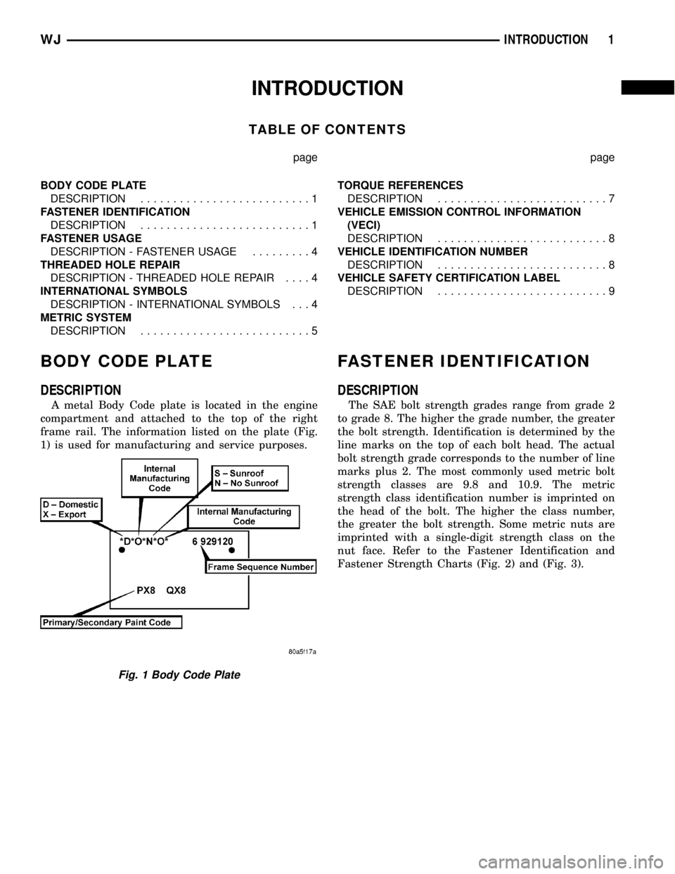
A metal Body Code plate is located in the engine
compartment and attached to the top of the right
frame rail. The information listed on the plate (Fig.
1) is used for manufacturing and service purposes.
FASTENER IDENTIFICATION
DESCRIPTION
The SAE bolt strength grades range from grade 2
to grade 8. The higher the grade number, the greater
the bolt strength. Identification is determined by the
line marks on the top of each bolt head. The actual
bolt strength grade corresponds to the number of line
marks plus 2. The most commonly used metric bolt
strength classes are 9.8 and 10.9. The metric
strength class identification number is imprinted on
the head of the bolt. The higher the class number,
the greater the bolt strength. Some metric nuts are
imprinted with a single-digit strength class on the
nut face. Refer to the Fastener Identification and
Fastener Strength Charts (Fig. 2) and (Fig. 3).
Fig. 1 Body Code Plate
WJINTRODUCTION 1
Page 5 of 2199
FASTENER USAGE
DESCRIPTION - FASTENER USAGE
WARNING: USE OF AN INCORRECT FASTENER
MAY RESULT IN COMPONENT DAMAGE OR PER-
SONAL INJURY.
Fasteners and torque specifications references in
this Service Manual are identified in metric and SAE
format.
During any maintenance or repair procedures, it is
important to salvage all fasteners (nuts, bolts, etc.)
for reassembly. If the fastener is not salvageable, a
fastener of equivalent specification must be used.
THREADED HOLE REPAIR
DESCRIPTION - THREADED HOLE REPAIR
Most stripped threaded holes can be repaired using
a Helicoilt. Follow the vehicle or Helicoiltrecommen-
dations for application and repair procedures.
INTERNATIONAL SYMBOLS
DESCRIPTION - INTERNATIONAL SYMBOLS
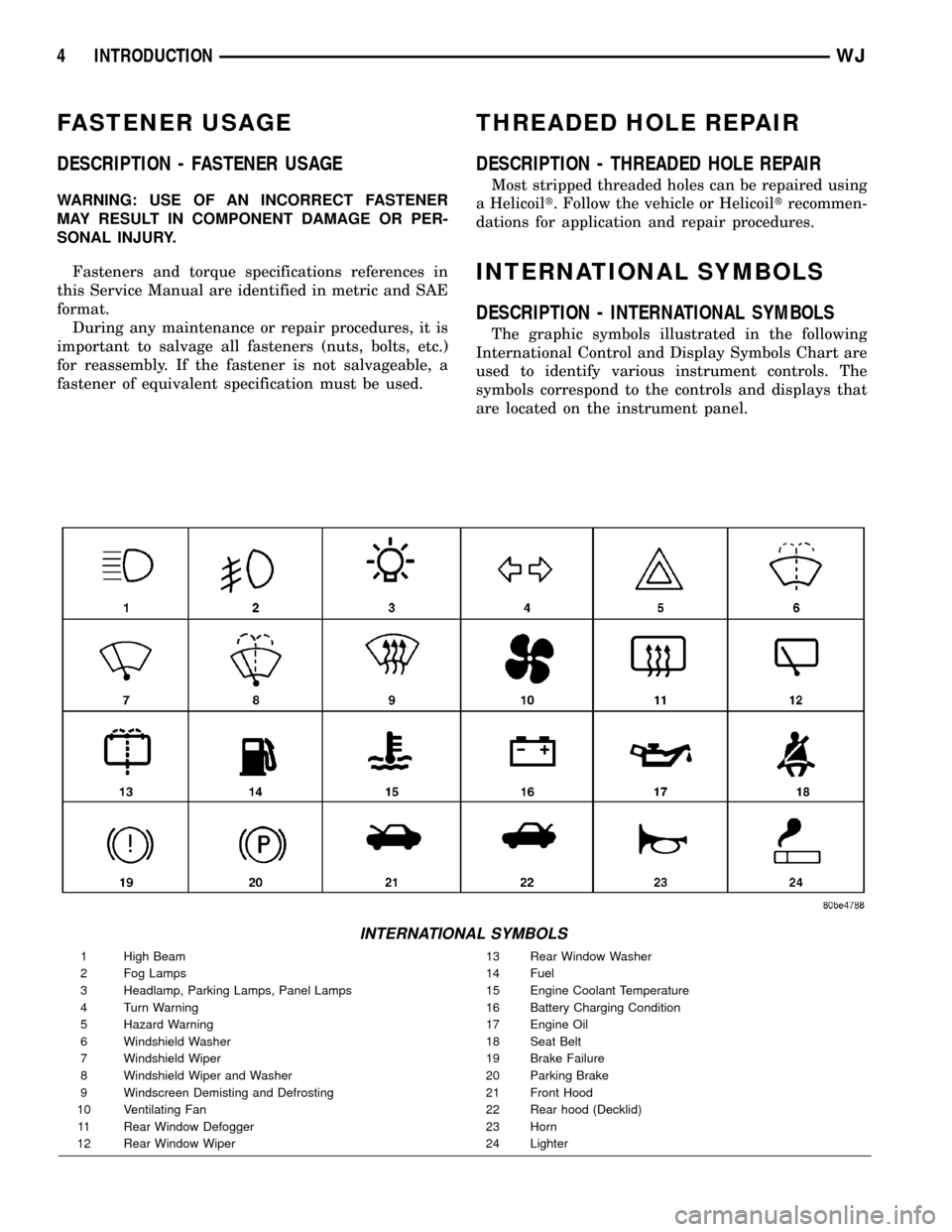
The graphic symbols illustrated in the following
International Control and Display Symbols Chart are
used to identify various instrument controls. The
symbols correspond to the controls and displays that
are located on the instrument panel.
INTERNATIONAL SYMBOLS
1 High Beam 13 Rear Window Washer
2 Fog Lamps 14 Fuel
3 Headlamp, Parking Lamps, Panel Lamps 15 Engine Coolant Temperature
4 Turn Warning 16 Battery Charging Condition
5 Hazard Warning 17 Engine Oil
6 Windshield Washer 18 Seat Belt
7 Windshield Wiper 19 Brake Failure
8 Windshield Wiper and Washer 20 Parking Brake
9 Windscreen Demisting and Defrosting 21 Front Hood
10 Ventilating Fan 22 Rear hood (Decklid)
11 Rear Window Defogger 23 Horn
12 Rear Window Wiper 24 Lighter
4 INTRODUCTIONWJ
Page 9 of 2199
VEHICLE EMISSION CONTROL
INFORMATION (VECI)
DESCRIPTION
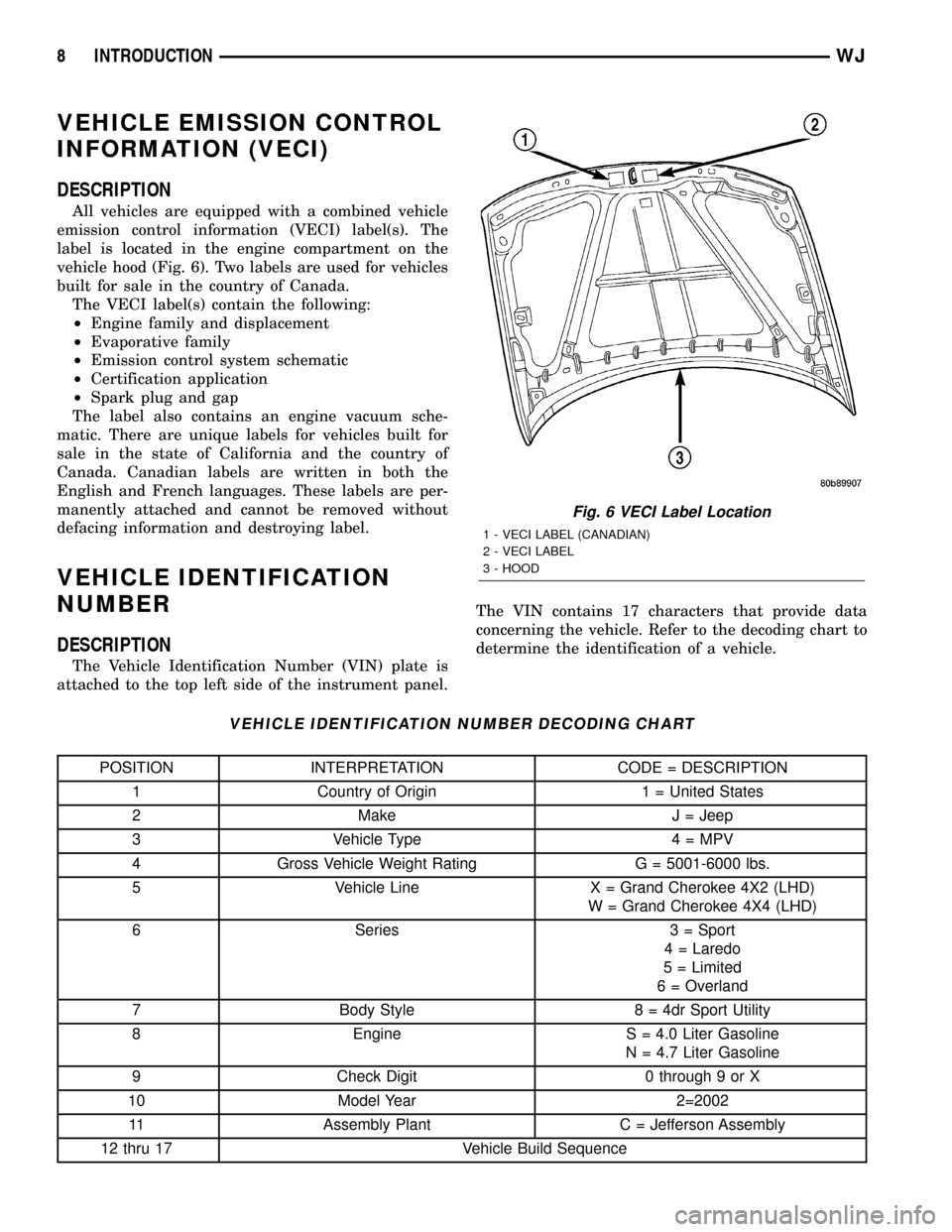
All vehicles are equipped with a combined vehicle
emission control information (VECI) label(s). The
label is located in the engine compartment on the
vehicle hood (Fig. 6). Two labels are used for vehicles
built for sale in the country of Canada.
The VECI label(s) contain the following:
²Engine family and displacement
²Evaporative family
²Emission control system schematic
²Certification application
²Spark plug and gap
The label also contains an engine vacuum sche-
matic. There are unique labels for vehicles built for
sale in the state of California and the country of
Canada. Canadian labels are written in both the
English and French languages. These labels are per-
manently attached and cannot be removed without
defacing information and destroying label.
VEHICLE IDENTIFICATION
NUMBER
DESCRIPTION
The Vehicle Identification Number (VIN) plate is
attached to the top left side of the instrument panel.The VIN contains 17 characters that provide data
concerning the vehicle. Refer to the decoding chart to
determine the identification of a vehicle.
VEHICLE IDENTIFICATION NUMBER DECODING CHART
POSITION INTERPRETATION CODE = DESCRIPTION
1 Country of Origin 1 = United States
2 Make J = Jeep
3 Vehicle Type 4 = MPV
4 Gross Vehicle Weight Rating G = 5001-6000 lbs.
5 Vehicle Line X = Grand Cherokee 4X2 (LHD)
W = Grand Cherokee 4X4 (LHD)
6 Series 3 = Sport
4 = Laredo
5 = Limited
6 = Overland
7 Body Style 8 = 4dr Sport Utility
8 Engine S = 4.0 Liter Gasoline
N = 4.7 Liter Gasoline
9 Check Digit 0 through 9 or X
10 Model Year 2=2002
11 Assembly Plant C = Jefferson Assembly
12 thru 17 Vehicle Build Sequence
Fig. 6 VECI Label Location
1 - VECI LABEL (CANADIAN)
2 - VECI LABEL
3 - HOOD
8 INTRODUCTIONWJ
Page 48 of 2199
(10) Start the engine and re-check for vibration. If
there is little or no change in vibration, move the
clamp to one of the other three positions. Repeat the
vibration test.
(11) If there is no difference in vibration at the
other positions, the source of the vibration may not
be propeller shaft.
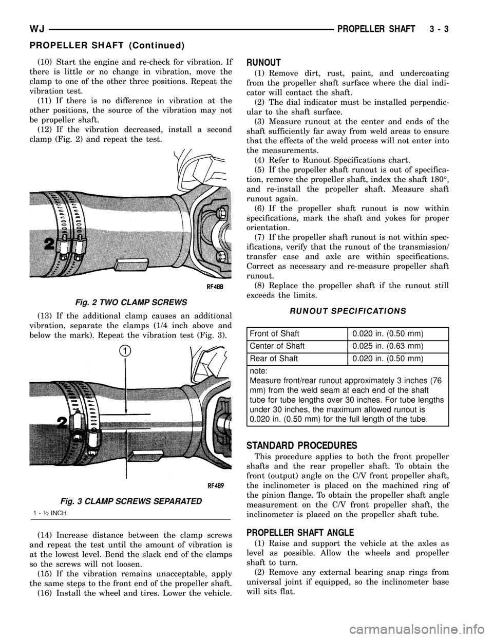
(12) If the vibration decreased, install a second
clamp (Fig. 2) and repeat the test.
(13) If the additional clamp causes an additional
vibration, separate the clamps (1/4 inch above and
below the mark). Repeat the vibration test (Fig. 3).
(14) Increase distance between the clamp screws
and repeat the test until the amount of vibration is
at the lowest level. Bend the slack end of the clamps
so the screws will not loosen.
(15) If the vibration remains unacceptable, apply
the same steps to the front end of the propeller shaft.
(16) Install the wheel and tires. Lower the vehicle.RUNOUT
(1) Remove dirt, rust, paint, and undercoating
from the propeller shaft surface where the dial indi-
cator will contact the shaft.
(2) The dial indicator must be installed perpendic-
ular to the shaft surface.
(3) Measure runout at the center and ends of the
shaft sufficiently far away from weld areas to ensure
that the effects of the weld process will not enter into
the measurements.
(4) Refer to Runout Specifications chart.
(5) If the propeller shaft runout is out of specifica-
tion, remove the propeller shaft, index the shaft 180É,
and re-install the propeller shaft. Measure shaft
runout again.
(6) If the propeller shaft runout is now within
specifications, mark the shaft and yokes for proper
orientation.
(7) If the propeller shaft runout is not within spec-
ifications, verify that the runout of the transmission/
transfer case and axle are within specifications.
Correct as necessary and re-measure propeller shaft
runout.
(8) Replace the propeller shaft if the runout still
exceeds the limits.
RUNOUT SPECIFICATIONS
Front of Shaft 0.020 in. (0.50 mm)
Center of Shaft 0.025 in. (0.63 mm)
Rear of Shaft 0.020 in. (0.50 mm)
note:
Measure front/rear runout approximately 3 inches (76
mm) from the weld seam at each end of the shaft
tube for tube lengths over 30 inches. For tube lengths
under 30 inches, the maximum allowed runout is
0.020 in. (0.50 mm) for the full length of the tube.
STANDARD PROCEDURES
This procedure applies to both the front propeller
shafts and the rear propeller shaft. To obtain the
front (output) angle on the C/V front propeller shaft,
the inclinometer is placed on the machined ring of
the pinion flange. To obtain the propeller shaft angle
measurement on the C/V front propeller shaft, the
inclinometer is placed on the propeller shaft tube.
PROPELLER SHAFT ANGLE
(1) Raise and support the vehicle at the axles as
level as possible. Allow the wheels and propeller
shaft to turn.
(2) Remove any external bearing snap rings from
universal joint if equipped, so the inclinometer base
will sits flat.
Fig. 2 TWO CLAMP SCREWS
Fig. 3 CLAMP SCREWS SEPARATED
1 - ó INCH
WJPROPELLER SHAFT 3 - 3
PROPELLER SHAFT (Continued)
Page 138 of 2199
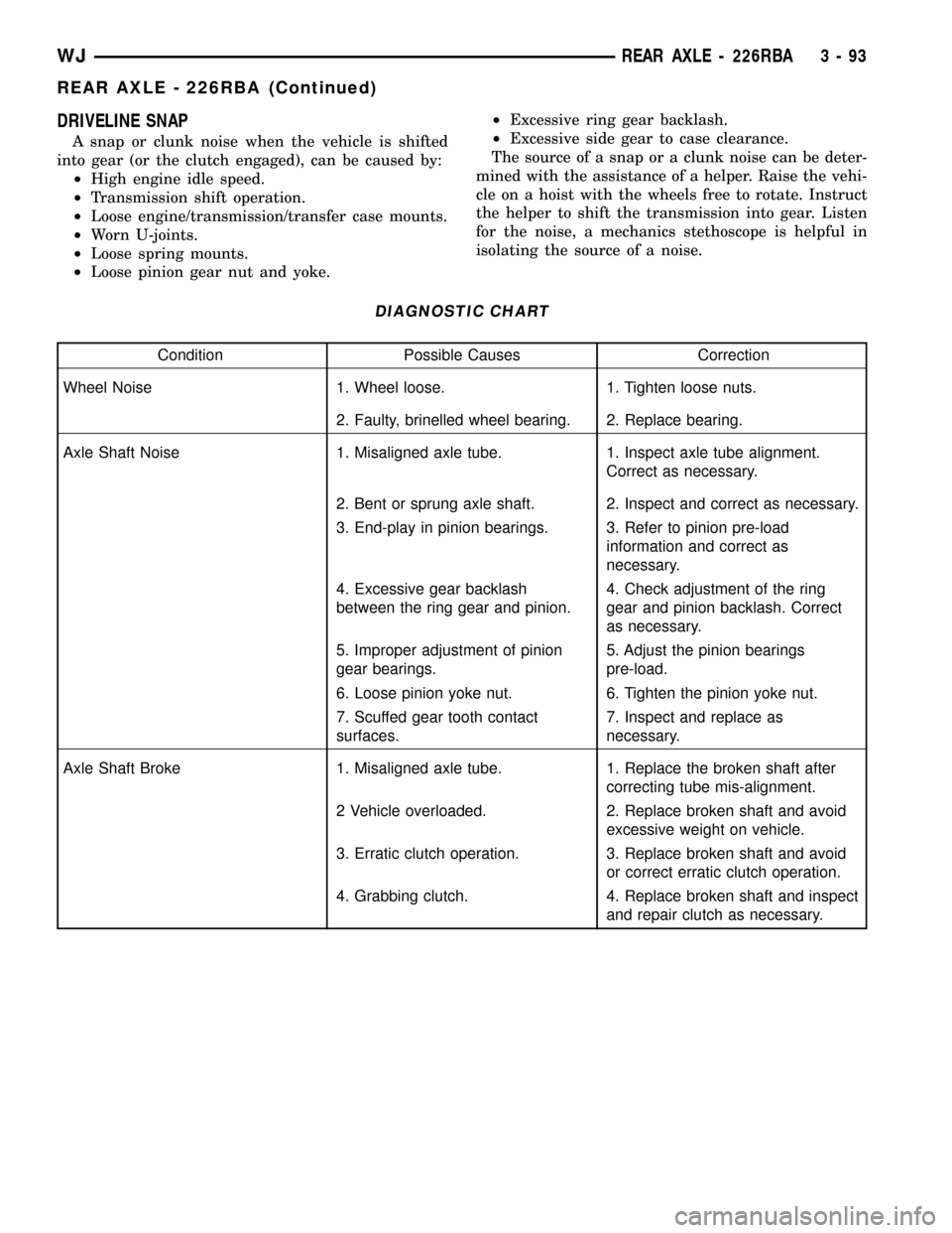
DRIVELINE SNAP
A snap or clunk noise when the vehicle is shifted
into gear (or the clutch engaged), can be caused by:
²High engine idle speed.
²Transmission shift operation.
²Loose engine/transmission/transfer case mounts.
²Worn U-joints.
²Loose spring mounts.
²Loose pinion gear nut and yoke.²Excessive ring gear backlash.
²Excessive side gear to case clearance.
The source of a snap or a clunk noise can be deter-
mined with the assistance of a helper. Raise the vehi-
cle on a hoist with the wheels free to rotate. Instruct
the helper to shift the transmission into gear. Listen
for the noise, a mechanics stethoscope is helpful in
isolating the source of a noise.
DIAGNOSTIC CHART
Condition Possible Causes Correction
Wheel Noise 1. Wheel loose. 1. Tighten loose nuts.
2. Faulty, brinelled wheel bearing. 2. Replace bearing.
Axle Shaft Noise 1. Misaligned axle tube. 1. Inspect axle tube alignment.
Correct as necessary.
2. Bent or sprung axle shaft. 2. Inspect and correct as necessary.
3. End-play in pinion bearings. 3. Refer to pinion pre-load
information and correct as
necessary.
4. Excessive gear backlash
between the ring gear and pinion.4. Check adjustment of the ring
gear and pinion backlash. Correct
as necessary.
5. Improper adjustment of pinion
gear bearings.5. Adjust the pinion bearings
pre-load.
6. Loose pinion yoke nut. 6. Tighten the pinion yoke nut.
7. Scuffed gear tooth contact
surfaces.7. Inspect and replace as
necessary.
Axle Shaft Broke 1. Misaligned axle tube. 1. Replace the broken shaft after
correcting tube mis-alignment.
2 Vehicle overloaded. 2. Replace broken shaft and avoid
excessive weight on vehicle.
3. Erratic clutch operation. 3. Replace broken shaft and avoid
or correct erratic clutch operation.
4. Grabbing clutch. 4. Replace broken shaft and inspect
and repair clutch as necessary.
WJREAR AXLE - 226RBA 3 - 93
REAR AXLE - 226RBA (Continued)
Page 224 of 2199
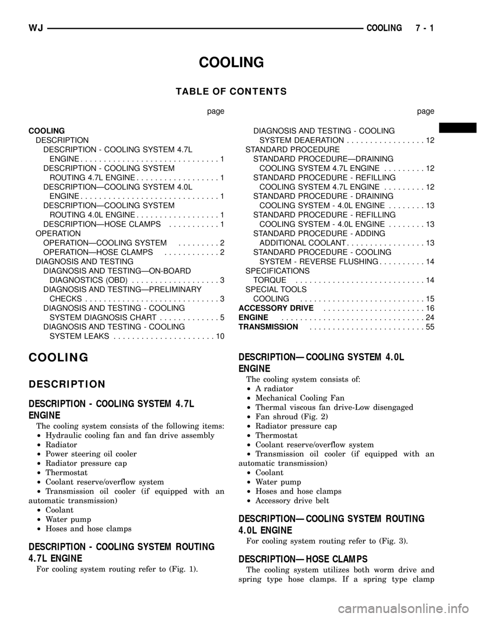
COOLING
TABLE OF CONTENTS
page page
COOLING
DESCRIPTION
DESCRIPTION - COOLING SYSTEM 4.7L
ENGINE..............................1
DESCRIPTION - COOLING SYSTEM
ROUTING 4.7L ENGINE..................1
DESCRIPTIONÐCOOLING SYSTEM 4.0L
ENGINE..............................1
DESCRIPTIONÐCOOLING SYSTEM
ROUTING 4.0L ENGINE..................1
DESCRIPTIONÐHOSE CLAMPS...........1
OPERATION
OPERATIONÐCOOLING SYSTEM.........2
OPERATIONÐHOSE CLAMPS............2
DIAGNOSIS AND TESTING
DIAGNOSIS AND TESTINGÐON-BOARD
DIAGNOSTICS (OBD)...................3
DIAGNOSIS AND TESTINGÐPRELIMINARY
CHECKS.............................3
DIAGNOSIS AND TESTING - COOLING
SYSTEM DIAGNOSIS CHART.............5
DIAGNOSIS AND TESTING - COOLING
SYSTEM LEAKS......................10DIAGNOSIS AND TESTING - COOLING
SYSTEM DEAERATION.................12
STANDARD PROCEDURE
STANDARD PROCEDUREÐDRAINING
COOLING SYSTEM 4.7L ENGINE.........12
STANDARD PROCEDURE - REFILLING
COOLING SYSTEM 4.7L ENGINE.........12
STANDARD PROCEDURE - DRAINING
COOLING SYSTEM - 4.0L ENGINE........13
STANDARD PROCEDURE - REFILLING
COOLING SYSTEM - 4.0L ENGINE........13
STANDARD PROCEDURE - ADDING
ADDITIONAL COOLANT.................13
STANDARD PROCEDURE - COOLING
SYSTEM - REVERSE FLUSHING..........14
SPECIFICATIONS
TORQUE............................14
SPECIAL TOOLS
COOLING...........................15
ACCESSORY DRIVE......................16
ENGINE...............................24
TRANSMISSION.........................55
COOLING
DESCRIPTION
DESCRIPTION - COOLING SYSTEM 4.7L
ENGINE
The cooling system consists of the following items:
²Hydraulic cooling fan and fan drive assembly
²Radiator
²Power steering oil cooler
²Radiator pressure cap
²Thermostat
²Coolant reserve/overflow system
²Transmission oil cooler (if equipped with an
automatic transmission)
²Coolant
²Water pump
²Hoses and hose clamps
DESCRIPTION - COOLING SYSTEM ROUTING
4.7L ENGINE
For cooling system routing refer to (Fig. 1).
DESCRIPTIONÐCOOLING SYSTEM 4.0L
ENGINE
The cooling system consists of:
²A radiator
²Mechanical Cooling Fan
²Thermal viscous fan drive-Low disengaged
²Fan shroud (Fig. 2)
²Radiator pressure cap
²Thermostat
²Coolant reserve/overflow system
²Transmission oil cooler (if equipped with an
automatic transmission)
²Coolant
²Water pump
²Hoses and hose clamps
²Accessory drive belt
DESCRIPTIONÐCOOLING SYSTEM ROUTING
4.0L ENGINE
For cooling system routing refer to (Fig. 3).
DESCRIPTIONÐHOSE CLAMPS
The cooling system utilizes both worm drive and
spring type hose clamps. If a spring type clamp
WJCOOLING 7 - 1
Page 227 of 2199
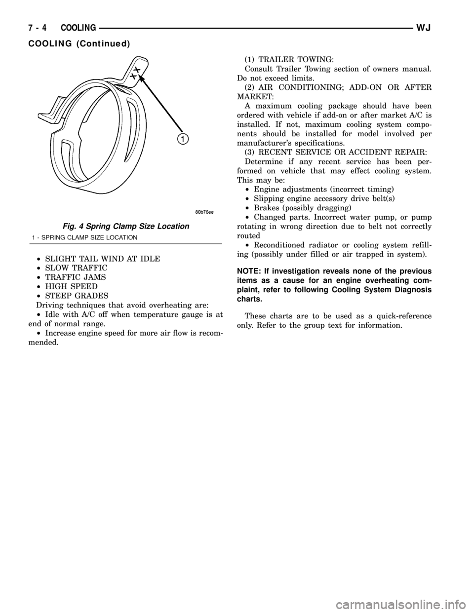
²SLIGHT TAIL WIND AT IDLE
²SLOW TRAFFIC
²TRAFFIC JAMS
²HIGH SPEED
²STEEP GRADES
Driving techniques that avoid overheating are:
²Idle with A/C off when temperature gauge is at
end of normal range.
²Increase engine speed for more air flow is recom-
mended.(1) TRAILER TOWING:
Consult Trailer Towing section of owners manual.
Do not exceed limits.
(2) AIR CONDITIONING; ADD-ON OR AFTER
MARKET:
A maximum cooling package should have been
ordered with vehicle if add-on or after market A/C is
installed. If not, maximum cooling system compo-
nents should be installed for model involved per
manufacturer's specifications.
(3) RECENT SERVICE OR ACCIDENT REPAIR:
Determine if any recent service has been per-
formed on vehicle that may effect cooling system.
This may be:
²Engine adjustments (incorrect timing)
²Slipping engine accessory drive belt(s)
²Brakes (possibly dragging)
²Changed parts. Incorrect water pump, or pump
rotating in wrong direction due to belt not correctly
routed
²Reconditioned radiator or cooling system refill-
ing (possibly under filled or air trapped in system).
NOTE: If investigation reveals none of the previous
items as a cause for an engine overheating com-
plaint, refer to following Cooling System Diagnosis
charts.
These charts are to be used as a quick-reference
only. Refer to the group text for information.
Fig. 4 Spring Clamp Size Location
1 - SPRING CLAMP SIZE LOCATION
7 - 4 COOLINGWJ
COOLING (Continued)
Page 228 of 2199
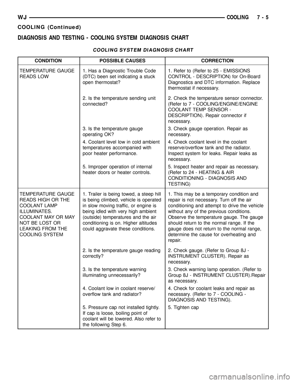
DIAGNOSIS AND TESTING - COOLING SYSTEM DIAGNOSIS CHART
COOLING SYSTEM DIAGNOSIS CHART
CONDITION POSSIBLE CAUSES CORRECTION
TEMPERATURE GAUGE
READS LOW1. Has a Diagnostic Trouble Code
(DTC) been set indicating a stuck
open thermostat?1. Refer to (Refer to 25 - EMISSIONS
CONTROL - DESCRIPTION) for On-Board
Diagnostics and DTC information. Replace
thermostat if necessary.
2. Is the temperature sending unit
connected?2. Check the temperature sensor connector.
(Refer to 7 - COOLING/ENGINE/ENGINE
COOLANT TEMP SENSOR -
DESCRIPTION). Repair connector if
necessary.
3. Is the temperature gauge
operating OK?3. Check gauge operation. Repair as
necessary.
4. Coolant level low in cold ambient
temperatures accompanied with
poor heater performance.4. Check coolant level in the coolant
reserve/overflow tank and the radiator.
Inspect system for leaks. Repair leaks as
necessary.
5. Improper operation of internal
heater doors or heater controls.5. Inspect heater and repair as necessary.
(Refer to 24 - HEATING & AIR
CONDITIONING - DIAGNOSIS AND
TESTING)
TEMPERATURE GAUGE
READS HIGH OR THE
COOLANT LAMP
ILLUMINATES.
COOLANT MAY OR MAY
NOT BE LOST OR
LEAKING FROM THE
COOLING SYSTEM1. Trailer is being towed, a steep hill
is being climbed, vehicle is operated
in slow moving traffic, or engine is
being idled with very high ambient
(outside) temperatures and the air
conditioning is on. Higher altitudes
could aggravate these conditions.1. This may be a temporary condition and
repair is not necessary. Turn off the air
conditioning and attempt to drive the vehicle
without any of the previous conditions.
Observe the temperature gauge. The gauge
should return to the normal range. If the
gauge does not return to the normal range,
determine the cause for overheating and
repair.
2. Is the temperature gauge reading
correctly?2. Check gauge. (Refer to Group 8J -
INSTRUMENT CLUSTER). Repair as
necessary.
3. Is the temperature warning
illuminating unnecessarily?3. Check warning lamp operation. (Refer to
Group 8J - INSTRUMENT CLUSTER).Repair
as necessary.
4. Coolant low in coolant reserve/
overflow tank and radiator?4. Check for coolant leaks and repair as
necessary. (Refer to 7 - COOLING -
DIAGNOSIS AND TESTING).
5. Pressure cap not installed tightly.
If cap is loose, boiling point of
coolant will be lowered. Also refer to
the following Step 6.5. Tighten cap
WJCOOLING 7 - 5
COOLING (Continued)
Page 240 of 2199
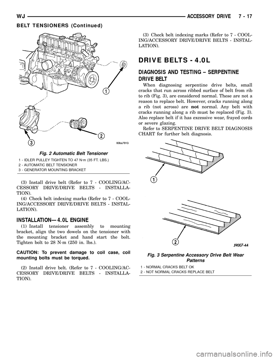
(3) Install drive belt (Refer to 7 - COOLING/AC-
CESSORY DRIVE/DRIVE BELTS - INSTALLA-
TION).
(4) Check belt indexing marks (Refer to 7 - COOL-
ING/ACCESSORY DRIVE/DRIVE BELTS - INSTAL-
LATION).
INSTALLATIONÐ4.0L ENGINE
(1) Install tensioner assembly to mounting
bracket, align the two dowels on the tensioner with
the mounting bracket and hand start the bolt.
Tighten bolt to 28 N´m (250 in. lbs.).
CAUTION: To prevent damage to coil case, coil
mounting bolts must be torqued.
(2) Install drive belt. (Refer to 7 - COOLING/AC-
CESSORY DRIVE/DRIVE BELTS - INSTALLA-
TION).(3) Check belt indexing marks (Refer to 7 - COOL-
ING/ACCESSORY DRIVE/DRIVE BELTS - INSTAL-
LATION).
DRIVE BELTS - 4.0L
DIAGNOSIS AND TESTING ± SERPENTINE
DRIVE BELT
When diagnosing serpentine drive belts, small
cracks that run across ribbed surface of belt from rib
to rib (Fig. 3), are considered normal. These are not a
reason to replace belt. However, cracks running along
a rib (not across) arenotnormal. Any belt with
cracks running along a rib must be replaced (Fig. 3).
Also replace belt if it has excessive wear, frayed cords
or severe glazing.
Refer to SERPENTINE DRIVE BELT DIAGNOSIS
CHART for further belt diagnosis.
Fig. 2 Automatic Belt Tensioner
1 - IDLER PULLEY TIGHTEN TO 47 N´m (35 FT. LBS.)
2 - AUTOMATIC BELT TENSIONER
3 - GENERATOR MOUNTING BRACKET
Fig. 3 Serpentine Accessory Drive Belt Wear
Patterns
1 - NORMAL CRACKS BELT OK
2 - NOT NORMAL CRACKS REPLACE BELT
WJACCESSORY DRIVE 7 - 17
BELT TENSIONERS (Continued)
Page 243 of 2199
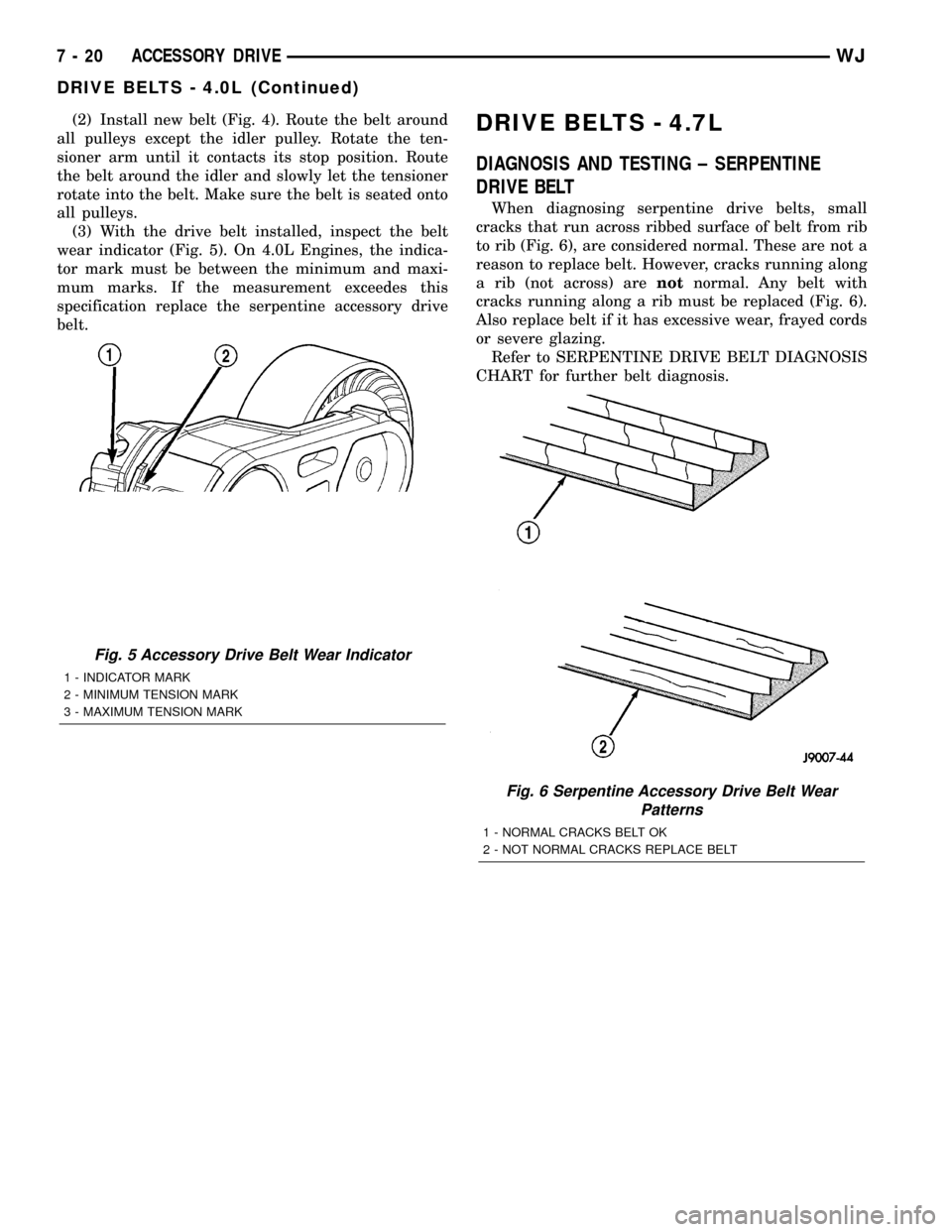
(2) Install new belt (Fig. 4). Route the belt around
all pulleys except the idler pulley. Rotate the ten-
sioner arm until it contacts its stop position. Route
the belt around the idler and slowly let the tensioner
rotate into the belt. Make sure the belt is seated onto
all pulleys.
(3) With the drive belt installed, inspect the belt
wear indicator (Fig. 5). On 4.0L Engines, the indica-
tor mark must be between the minimum and maxi-
mum marks. If the measurement exceedes this
specification replace the serpentine accessory drive
belt.DRIVE BELTS - 4.7L
DIAGNOSIS AND TESTING ± SERPENTINE
DRIVE BELT
When diagnosing serpentine drive belts, small
cracks that run across ribbed surface of belt from rib
to rib (Fig. 6), are considered normal. These are not a
reason to replace belt. However, cracks running along
a rib (not across) arenotnormal. Any belt with
cracks running along a rib must be replaced (Fig. 6).
Also replace belt if it has excessive wear, frayed cords
or severe glazing.
Refer to SERPENTINE DRIVE BELT DIAGNOSIS
CHART for further belt diagnosis.
Fig. 5 Accessory Drive Belt Wear Indicator
1 - INDICATOR MARK
2 - MINIMUM TENSION MARK
3 - MAXIMUM TENSION MARK
Fig. 6 Serpentine Accessory Drive Belt Wear
Patterns
1 - NORMAL CRACKS BELT OK
2 - NOT NORMAL CRACKS REPLACE BELT
7 - 20 ACCESSORY DRIVEWJ
DRIVE BELTS - 4.0L (Continued)