fig 37 JEEP GRAND CHEROKEE 2002 WJ / 2.G Workshop Manual
[x] Cancel search | Manufacturer: JEEP, Model Year: 2002, Model line: GRAND CHEROKEE, Model: JEEP GRAND CHEROKEE 2002 WJ / 2.GPages: 2199, PDF Size: 76.01 MB
Page 2 of 2199

INTRODUCTION
TABLE OF CONTENTS
page page
BODY CODE PLATE
DESCRIPTION..........................1
FASTENER IDENTIFICATION
DESCRIPTION..........................1
FASTENER USAGE
DESCRIPTION - FASTENER USAGE.........4
THREADED HOLE REPAIR
DESCRIPTION - THREADED HOLE REPAIR....4
INTERNATIONAL SYMBOLS
DESCRIPTION - INTERNATIONAL SYMBOLS . . . 4
METRIC SYSTEM
DESCRIPTION..........................5TORQUE REFERENCES
DESCRIPTION..........................7
VEHICLE EMISSION CONTROL INFORMATION
(VECI)
DESCRIPTION..........................8
VEHICLE IDENTIFICATION NUMBER
DESCRIPTION..........................8
VEHICLE SAFETY CERTIFICATION LABEL
DESCRIPTION..........................9
BODY CODE PLATE
DESCRIPTION
A metal Body Code plate is located in the engine
compartment and attached to the top of the right
frame rail. The information listed on the plate (Fig.
1) is used for manufacturing and service purposes.
FASTENER IDENTIFICATION
DESCRIPTION
The SAE bolt strength grades range from grade 2
to grade 8. The higher the grade number, the greater
the bolt strength. Identification is determined by the
line marks on the top of each bolt head. The actual
bolt strength grade corresponds to the number of line
marks plus 2. The most commonly used metric bolt
strength classes are 9.8 and 10.9. The metric
strength class identification number is imprinted on
the head of the bolt. The higher the class number,
the greater the bolt strength. Some metric nuts are
imprinted with a single-digit strength class on the
nut face. Refer to the Fastener Identification and
Fastener Strength Charts (Fig. 2) and (Fig. 3).
Fig. 1 Body Code Plate
WJINTRODUCTION 1
Page 3 of 2199

Fig. 2 FASTENER IDENTIFICATION
2 INTRODUCTIONWJ
FASTENER IDENTIFICATION (Continued)
Page 4 of 2199

Fig. 3 FASTENER STRENGTH
WJINTRODUCTION 3
FASTENER IDENTIFICATION (Continued)
Page 6 of 2199
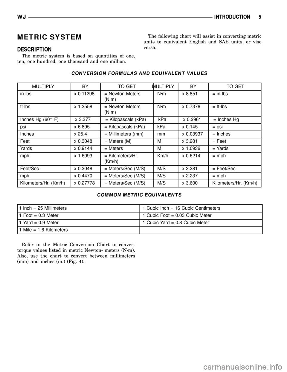
METRIC SYSTEM
DESCRIPTION
The metric system is based on quantities of one,
ten, one hundred, one thousand and one million.The following chart will assist in converting metric
units to equivalent English and SAE units, or vise
versa.
CONVERSION FORMULAS AND EQUIVALENT VALUES
MULTIPLY BY TO GET MULTIPLY BY TO GET
in-lbs x 0.11298 = Newton Meters
(N´m)N´m x 8.851 = in-lbs
ft-lbs x 1.3558 = Newton Meters
(N´m)N´m x 0.7376 = ft-lbs
Inches Hg (60É F) x 3.377 = Kilopascals (kPa) kPa x 0.2961 = Inches Hg
psi x 6.895 = Kilopascals (kPa) kPa x 0.145 = psi
Inches x 25.4 = Millimeters (mm) mm x 0.03937 = Inches
Feet x 0.3048 = Meters (M) M x 3.281 = Feet
Yards x 0.9144 = Meters M x 1.0936 = Yards
mph x 1.6093 = Kilometers/Hr.
(Km/h)Km/h x 0.6214 = mph
Feet/Sec x 0.3048 = Meters/Sec (M/S) M/S x 3.281 = Feet/Sec
mph x 0.4470 = Meters/Sec (M/S) M/S x 2.237 = mph
Kilometers/Hr. (Km/h) x 0.27778 = Meters/Sec (M/S) M/S x 3.600 Kilometers/Hr. (Km/h)
COMMON METRIC EQUIVALENTS
1 inch = 25 Millimeters 1 Cubic Inch = 16 Cubic Centimeters
1 Foot = 0.3 Meter 1 Cubic Foot = 0.03 Cubic Meter
1 Yard = 0.9 Meter 1 Cubic Yard = 0.8 Cubic Meter
1 Mile = 1.6 Kilometers
Refer to the Metric Conversion Chart to convert
torque values listed in metric Newton- meters (N´m).
Also, use the chart to convert between millimeters
(mm) and inches (in.) (Fig. 4).
WJINTRODUCTION 5
Page 7 of 2199

Fig. 4 METRIC CONVERSION CHART
6 INTRODUCTIONWJ
METRIC SYSTEM (Continued)
Page 8 of 2199

TORQUE REFERENCES
DESCRIPTION
Individual Torque Charts appear within many or
the Groups. Refer to the Standard Torque Specifica-tions Chart for torque references not listed in the
individual torque charts (Fig. 5).
Fig. 5 TORQUE SPECIFICATIONS
WJINTRODUCTION 7
Page 9 of 2199
VEHICLE EMISSION CONTROL
INFORMATION (VECI)
DESCRIPTION
All vehicles are equipped with a combined vehicle
emission control information (VECI) label(s). The
label is located in the engine compartment on the
vehicle hood (Fig. 6). Two labels are used for vehicles
built for sale in the country of Canada.
The VECI label(s) contain the following:
²Engine family and displacement
²Evaporative family
²Emission control system schematic
²Certification application
²Spark plug and gap
The label also contains an engine vacuum sche-
matic. There are unique labels for vehicles built for
sale in the state of California and the country of
Canada. Canadian labels are written in both the
English and French languages. These labels are per-
manently attached and cannot be removed without
defacing information and destroying label.
VEHICLE IDENTIFICATION
NUMBER
DESCRIPTION
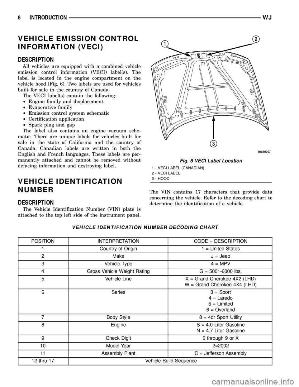
The Vehicle Identification Number (VIN) plate is
attached to the top left side of the instrument panel.The VIN contains 17 characters that provide data
concerning the vehicle. Refer to the decoding chart to
determine the identification of a vehicle.
VEHICLE IDENTIFICATION NUMBER DECODING CHART
POSITION INTERPRETATION CODE = DESCRIPTION
1 Country of Origin 1 = United States
2 Make J = Jeep
3 Vehicle Type 4 = MPV
4 Gross Vehicle Weight Rating G = 5001-6000 lbs.
5 Vehicle Line X = Grand Cherokee 4X2 (LHD)
W = Grand Cherokee 4X4 (LHD)
6 Series 3 = Sport
4 = Laredo
5 = Limited
6 = Overland
7 Body Style 8 = 4dr Sport Utility
8 Engine S = 4.0 Liter Gasoline
N = 4.7 Liter Gasoline
9 Check Digit 0 through 9 or X
10 Model Year 2=2002
11 Assembly Plant C = Jefferson Assembly
12 thru 17 Vehicle Build Sequence
Fig. 6 VECI Label Location
1 - VECI LABEL (CANADIAN)
2 - VECI LABEL
3 - HOOD
8 INTRODUCTIONWJ
Page 10 of 2199

VEHICLE SAFETY
CERTIFICATION LABEL
DESCRIPTION
A vehicle safety certification label (Fig. 7) is
attached to every DaimlerChrysler Corporation vehi-
cle. The label certifies that the vehicle conforms to all
applicable Federal Motor Vehicle Safety Standards.
The label also lists:
²Month and year of vehicle manufacture.
²Gross Vehicle Weight Rating (GVWR). The gross
front and rear axle weight ratings (GAWR's) are
based on a minimum rim size and maximum cold tire
inflation pressure.
²Vehicle Identification Number (VIN).
²Type of vehicle.
²Type of rear wheels.
²Bar code.
²Month, Day and Hour (MDH) of final assembly.
²Paint and Trim codes.
²Country of origin.The label is located on the driver-side door
shut-face.
Fig. 7 VEHICLE SAFETY CERTIFICATION LABEL -
TYPICAL
WJINTRODUCTION 9
Page 12 of 2199
LUBRICATION & MAINTENANCE
TABLE OF CONTENTS
page page
LUBRICATION & MAINTENANCE
SPECIFICATIONS - FLUID CAPACITIES.......1
INTERNATIONAL SYMBOLS
DESCRIPTION..........................2
PARTS & LUBRICANT RECOMMENDATION
STANDARD PROCEDURE - PARTS &
LUBRICANT RECOMMENDATIONS.........2
FLUID TYPES
DESCRIPTION
DESCRIPTION - ENGINE COOLANT........2
DESCRIPTION - ENGINE COOLANT........3
ENGINE OIL..........................4
DESCRIPTION - ENGINE OIL.............4
DESCRIPTION........................5
DESCRIPTION - TRANSFER CASE - NV242 . . 5
DESCRIPTION - TRANSFER CASE - NV247 . . 5
DESCRIPTION - AUTOMATIC
TRANSMISSION FLUID..................5
DESCRIPTION - ENGINE OIL - DIESEL
ENGINES............................6OPERATION - AUTOMATIC TRANSMISSION
FLUID...............................6
FLUID FILL/CHECK LOCATIONS
INSPECTION - FLUID FILL/CHECK
LOCATIONS..........................6
MAINTENANCE SCHEDULES
DESCRIPTION..........................6
LIFT POINTS
STANDARD PROCEDURE - HOISTING AND
JACKING RECOMMENDATIONS...........6
JUMP STARTING
STANDARD PROCEDURE - JUMP STARTING . . 7
EMERGENCY TOW HOOKS
DESCRIPTION..........................8
TOWING
STANDARD PROCEDURE - TOWING
RECOMMENDATIONS...................8
LUBRICATION &
MAINTENANCE
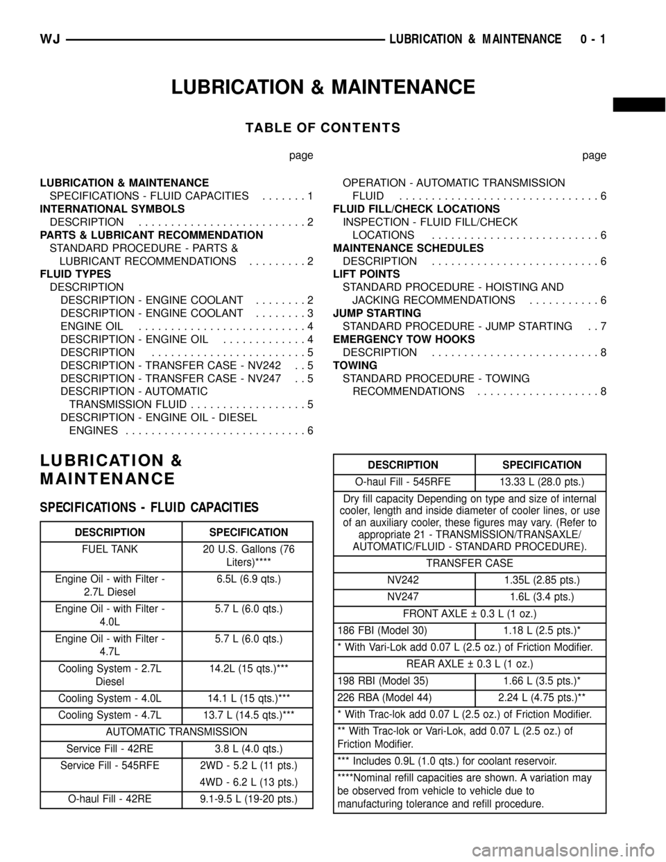
SPECIFICATIONS - FLUID CAPACITIES
DESCRIPTION SPECIFICATION
FUEL TANK 20 U.S. Gallons (76
Liters)****
Engine Oil - with Filter -
2.7L Diesel6.5L (6.9 qts.)
Engine Oil - with Filter -
4.0L5.7 L (6.0 qts.)
Engine Oil - with Filter -
4.7L5.7 L (6.0 qts.)
Cooling System - 2.7L
Diesel14.2L (15 qts.)***
Cooling System - 4.0L 14.1 L (15 qts.)***
Cooling System - 4.7L 13.7 L (14.5 qts.)***
AUTOMATIC TRANSMISSION
Service Fill - 42RE 3.8 L (4.0 qts.)
Service Fill - 545RFE 2WD - 5.2 L (11 pts.)
4WD - 6.2 L (13 pts.)
O-haul Fill - 42RE 9.1-9.5 L (19-20 pts.)
DESCRIPTION SPECIFICATION
O-haul Fill - 545RFE 13.33 L (28.0 pts.)
Dry fill capacity Depending on type and size of internal
cooler, length and inside diameter of cooler lines, or use
of an auxiliary cooler, these figures may vary. (Refer to
appropriate 21 - TRANSMISSION/TRANSAXLE/
AUTOMATIC/FLUID - STANDARD PROCEDURE).
TRANSFER CASE
NV242 1.35L (2.85 pts.)
NV247 1.6L (3.4 pts.)
FRONT AXLE 0.3 L (1 oz.)
186 FBI (Model 30) 1.18 L (2.5 pts.)*
* With Vari-Lok add 0.07 L (2.5 oz.) of Friction Modifier.
REAR AXLE 0.3 L (1 oz.)
198 RBI (Model 35) 1.66 L (3.5 pts.)*
226 RBA (Model 44) 2.24 L (4.75 pts.)**
* With Trac-lok add 0.07 L (2.5 oz.) of Friction Modifier.
** With Trac-lok or Vari-Lok, add 0.07 L (2.5 oz.) of
Friction Modifier.
*** Includes 0.9L (1.0 qts.) for coolant reservoir.
****Nominal refill capacities are shown. A variation may
be observed from vehicle to vehicle due to
manufacturing tolerance and refill procedure.
WJLUBRICATION & MAINTENANCE 0 - 1
Page 13 of 2199

INTERNATIONAL SYMBOLS
DESCRIPTION
DaimlerChrysler Corporation uses international
symbols to identify engine compartment lubricant
and fluid inspection and fill locations (Fig. 1).
PARTS & LUBRICANT
RECOMMENDATION
STANDARD PROCEDURE - PARTS &
LUBRICANT RECOMMENDATIONS
Lubricating grease is rated for quality and usage
by the NLGI. All approved products have the NLGI
symbol (Fig. 2) on the label. At the bottom NLGI
symbol is the usage and quality identification letters.
Wheel bearing lubricant is identified by the letter
ªGº. Chassis lubricant is identified by the latter ªLº.
The letter following the usage letter indicates the
quality of the lubricant. The following symbols indi-
cate the highest quality.
When service is required, DaimlerChrysler Corpo-
ration recommends that only Mopartbrand parts,
lubricants and chemicals be used. Mopar provides
the best engineered products for servicing
DaimlerChrysler Corporation vehicles.
FLUID TYPES
DESCRIPTION
DESCRIPTION - ENGINE COOLANT
ETHYLENE-GLYCOL MIXTURES
CAUTION: Richer antifreeze mixtures cannot be
measured with normal field equipment and can
cause problems associated with 100 percent ethyl-
ene-glycol.
The required ethylene-glycol (antifreeze) and water
mixture depends upon the climate and vehicle oper-
ating conditions. The recommended mixture of 50/50
ethylene-glycol and water will provide protection
against freezing to -37 deg. C (-35 deg. F). The anti-
freeze concentrationmust alwaysbe a minimum of
44 percent, year-round in all climates.If percentage
is lower than 44 percent, engine parts may be
eroded by cavitation, and cooling system com-
ponents may be severely damaged by corrosion.
Maximum protection against freezing is provided
with a 68 percent antifreeze concentration, which
prevents freezing down to -67.7 deg. C (-90 deg. F). A
higher percentage will freeze at a warmer tempera-
ture. Also, a higher percentage of antifreeze can
cause the engine to overheat because the specific
heat of antifreeze is lower than that of water.
Use of 100 percent ethylene-glycol will cause for-
mation of additive deposits in the system, as the cor-
rosion inhibitive additives in ethylene-glycol require
the presence of water to dissolve. The deposits act as
insulation, causing temperatures to rise to as high as
149 deg. C (300) deg. F). This temperature is hot
enough to melt plastic and soften solder. The
increased temperature can result in engine detona-
tion. In addition, 100 percent ethylene-glycol freezes
at 22 deg. C (-8 deg. F ).
PROPYLENE-GLYCOL MIXTURES
It's overall effective temperature range is smaller
than that of ethylene-glycol. The freeze point of 50/50
propylene-glycol and water is -32 deg. C (-26 deg. F).
5 deg. C higher than ethylene-glycol's freeze point.
The boiling point (protection against summer boil-
over) of propylene-glycol is 125 deg. C (257 deg. F )
at 96.5 kPa (14 psi), compared to 128 deg. C (263
deg. F) for ethylene-glycol. Use of propylene-glycol
can result in boil-over or freeze-up on a cooling sys-
tem designed for ethylene-glycol. Propylene glycol
also has poorer heat transfer characteristics than
ethylene glycol. This can increase cylinder head tem-
peratures under certain conditions.
Fig. 1 INTERNATIONAL SYMBOLS
Fig. 2 NLGI Symbol
1 - WHEEL BEARINGS
2 - CHASSIS LUBRICATION
3 - CHASSIS AND WHEEL BEARINGS
0 - 2 LUBRICATION & MAINTENANCEWJ