plenum JEEP GRAND CHEROKEE 2002 WJ / 2.G Workshop Manual
[x] Cancel search | Manufacturer: JEEP, Model Year: 2002, Model line: GRAND CHEROKEE, Model: JEEP GRAND CHEROKEE 2002 WJ / 2.GPages: 2199, PDF Size: 76.01 MB
Page 89 of 2199
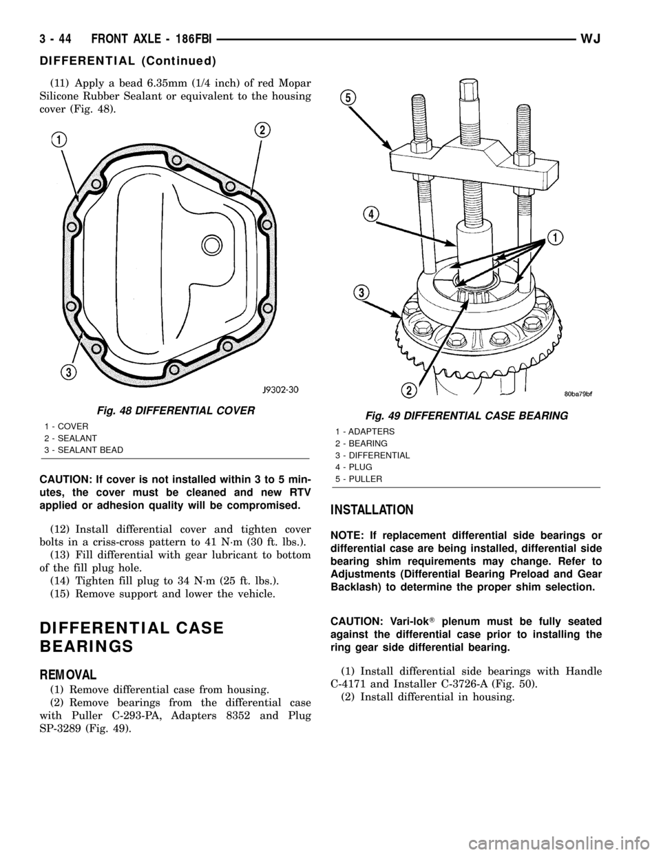
(11) Apply a bead 6.35mm (1/4 inch) of red Mopar
Silicone Rubber Sealant or equivalent to the housing
cover (Fig. 48).
CAUTION: If cover is not installed within 3 to 5 min-
utes, the cover must be cleaned and new RTV
applied or adhesion quality will be compromised.
(12) Install differential cover and tighten cover
bolts in a criss-cross pattern to 41 N´m (30 ft. lbs.).
(13) Fill differential with gear lubricant to bottom
of the fill plug hole.
(14) Tighten fill plug to 34 N´m (25 ft. lbs.).
(15) Remove support and lower the vehicle.
DIFFERENTIAL CASE
BEARINGS
REMOVAL
(1) Remove differential case from housing.
(2) Remove bearings from the differential case
with Puller C-293-PA, Adapters 8352 and Plug
SP-3289 (Fig. 49).
INSTALLATION
NOTE: If replacement differential side bearings or
differential case are being installed, differential side
bearing shim requirements may change. Refer to
Adjustments (Differential Bearing Preload and Gear
Backlash) to determine the proper shim selection.
CAUTION: Vari-lokTplenum must be fully seated
against the differential case prior to installing the
ring gear side differential bearing.
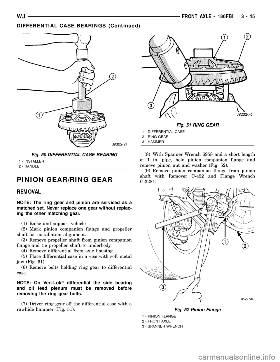
(1) Install differential side bearings with Handle
C-4171 and Installer C-3726-A (Fig. 50).
(2) Install differential in housing.
Fig. 48 DIFFERENTIAL COVER
1 - COVER
2 - SEALANT
3 - SEALANT BEADFig. 49 DIFFERENTIAL CASE BEARING
1 - ADAPTERS
2 - BEARING
3 - DIFFERENTIAL
4 - PLUG
5 - PULLER
3 - 44 FRONT AXLE - 186FBIWJ
DIFFERENTIAL (Continued)
Page 90 of 2199
PINION GEAR/RING GEAR
REMOVAL
NOTE: The ring gear and pinion are serviced as a
matched set. Nevar replace one gear without replac-
ing the other matching gear.
(1) Raise and support vehicle
(2) Mark pinion companion flange and propeller
shaft for installation alignment.
(3) Remove propeller shaft from pinion companion
flange and tie propeller shaft to underbody.
(4) Remove differential from axle housing.
(5) Place differential case in a vise with soft metal
jaw (Fig. 51).
(6) Remove bolts holding ring gear to differential
case.
NOTE: On Veri-LokTdifferential the side bearing
and oil feed plenum must be removed before
removing the ring gear bolts.
(7) Driver ring gear off the differential case with a
rawhide hammer (Fig. 51).(8) With Spanner Wrench 6958 and a short length
of 1 in. pipe, hold pinion companion flange and
remove pinion nut and washer (Fig. 52).
(9) Remove pinion companion flange from pinion
shaft with Remover C-452 and Flange Wrench
C-3281.
Fig. 50 DIFFERENTIAL CASE BEARING
1 - INSTALLER
2 - HANDLE
Fig. 51 RING GEAR
1 - DIFFERENTIAL CASE
2 - RING GEAR
3 - HAMMER
Fig. 52 Pinion Flange
1 - PINION FLANGE
2 - FRONT AXLE
3 - SPANNER WRENCH
WJFRONT AXLE - 186FBI 3 - 45
DIFFERENTIAL CASE BEARINGS (Continued)
Page 94 of 2199
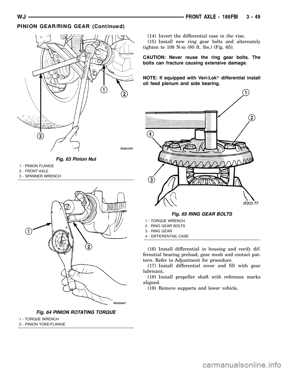
(14) Invert the differential case in the vise.
(15) Install new ring gear bolts and alternately
tighten to 108 N´m (80 ft. lbs.) (Fig. 65).
CAUTION: Never reuse the ring gear bolts. The
bolts can fracture causing extensive damage.
NOTE: If equipped with Veri-LokTdifferential install
oil feed plenum and side bearing.
(16) Install differential in housing and verify dif-
ferential bearing preload, gear mesh and contact pat-
tern. Refer to Adjustment for procedure.
(17) Install differential cover and fill with gear
lubricant.
(18) Install propeller shaft with reference marks
aligned.
(19) Remove supports and lower vehicle.
Fig. 63 Pinion Nut
1 - PINION FLANGE
2 - FRONT AXLE
3 - SPANNER WRENCH
Fig. 64 PINION ROTATING TORQUE
1 - TORQUE WRENCH
2 - PINION YOKE/FLANGE
Fig. 65 RING GEAR BOLTS
1 - TORQUE WRENCH
2 - RING GEAR BOLTS
3 - RING GEAR
4 - DIFFERENTIAL CASE
WJFRONT AXLE - 186FBI 3 - 49
PINION GEAR/RING GEAR (Continued)
Page 169 of 2199
CAUTION: Vari-lokTplenum must be seated against
the differential case prior to installing the ring gear
side differential bearing.
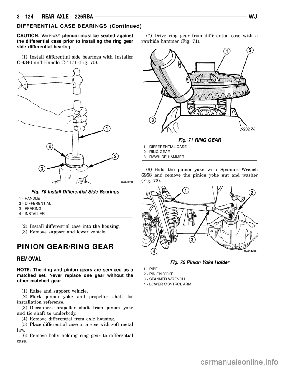
(1) Install differential side bearings with Installer
C-4340 and Handle C-4171 (Fig. 70).
(2) Install differential case into the housing.
(3) Remove support and lower vehicle.
PINION GEAR/RING GEAR
REMOVAL
NOTE: The ring and pinion gears are serviced as a
matched set. Never replace one gear without the
other matched gear.
(1) Raise and support vehicle.
(2) Mark pinion yoke and propeller shaft for
installation reference.
(3) Disconnect propeller shaft from pinion yoke
and tie shaft to underbody.
(4) Remove differential from axle housing.
(5) Place differential case in a vise with soft metal
jaw.
(6) Remove bolts holding ring gear to differential
case.(7) Drive ring gear from differential case with a
rawhide hammer (Fig. 71).
(8) Hold the pinion yoke with Spanner Wrench
6958 and remove the pinion yoke nut and washer
(Fig. 72).
Fig. 70 Install Differential Side Bearings
1 - HANDLE
2 - DIFFERENTIAL
3 - BEARING
4 - INSTALLER
Fig. 71 RING GEAR
1 - DIFFERENTIAL CASE
2 - RING GEAR
3 - RAWHIDE HAMMER
Fig. 72 Pinion Yoke Holder
1 - PIPE
2 - PINION YOKE
3 - SPANNER WRENCH
4 - LOWER CONTROL ARM
3 - 124 REAR AXLE - 226RBAWJ
DIFFERENTIAL CASE BEARINGS (Continued)
Page 174 of 2199
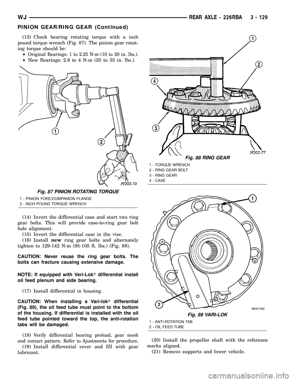
(13) Check bearing rotating torque with a inch
pound torque wrench (Fig. 87). The pinion gear rotat-
ing torque should be:
²
Original Bearings: 1 to 2.25 N´m (10 to 20 in. lbs.).
²New Bearings: 2.8 to 4 N´m (25 to 35 in. lbs.).
(14) Invert the differential case and start two ring
gear bolts. This will provide case-to-ring gear bolt
hole alignment.
(15) Invert the differential case in the vise.
(16) Installnewring gear bolts and alternately
tighten to 129-142 N´m (95-105 ft. lbs.) (Fig. 88).
CAUTION: Never reuse the ring gear bolts. The
bolts can fracture causing extensive damage.
NOTE: If equipped with Veri-LokTdifferential install
oil feed plenum and side bearing.
(17) Install differential in housing.
CAUTION: When installing a Vari-lokTdifferential
(Fig. 89), the oil feed tube must point to the bottom
of the housing. If differential is installed with the oil
feed tube pointed toward the top, the anti-rotation
tabs will be damaged.
(18)
Verify differential bearing preload, gear mesh
and contact pattern. Refer to Ajustments for procedure.
(19) Install differential cover and fill with gear
lubricant.(20) Install the propeller shaft with the reference
marks aligned.
(21) Remove supports and lower vehicle.
Fig. 87 PINION ROTATING TORQUE
1 - PINION YOKE/COMPANION FLANGE
2 - INCH POUND TORQUE WRENCH
Fig. 88 RING GEAR
1 - TORQUE WRENCH
2 - RING GEAR BOLT
3 - RING GEAR
4 - CASE
Fig. 89 VARI-LOK
1 - ANTI-ROTATION TAB
2 - OIL FEED TUBE
WJREAR AXLE - 226RBA 3 - 129
PINION GEAR/RING GEAR (Continued)
Page 281 of 2199
AUDIO
DESCRIPTION
An audio system is standard factory-installed
equipment on this model. The standard equipment
audio system includes an AM/FM/cassette (RBB sales
code) radio receiver, and speakers in six locations.
Several combinations of radio receivers and speaker
systems are offered as optional equipment on this
model. The audio system uses an ignition switched
control of battery current so that the system will only
operate when the ignition switch is in the On or
Accessory positions.
A Compact Disc (CD) changer with a ten disc mag-
azine, remote radio switches with six functions
mounted to the backs of the steering wheel spokes,
and a memory system that automatically stores and
recalls up to twenty radio station presets (ten AM
and ten FM) and the last station listened to for two
drivers are optional factory-installed equipment on
this model. Refer to Electrical, Power Seats for more
information on the memory system.
The audio system includes the following compo-
nents:
²Antenna
²Compact disc changer (available with RBP sales
code radio receivers only)
²Power amplifier (with premium speaker system
only)
²Radio noise suppression components
²Radio receiver
²Remote radio switches
²Speakers
Certain functions and features of the audio system
rely upon resources shared with other electronic
modules in the vehicle over the Programmable Com-
munications Interface (PCI) data bus network. The
PCI data bus network allows the sharing of sensor
information. This helps to reduce wire harness com-
plexity, internal controller hardware, and component
sensor current loads. At the same time, this system
provides increased reliability, enhanced diagnostics,
and allows the addition of many new feature capabil-
ities. For diagnosis of these electronic modules or of
the PCI data bus network, the use of a DRB scan
tool and the proper Diagnostic Procedures manual
are recommended.
The other electronic modules that may affect audio
system operation are as follows:
²Body Control Module (BCM)- (Refer to 8 -
ELECTRICAL/ELECTRONIC CONTROL MOD-
ULES/BODY CONTROL/CENTRAL TIMER MODUL
- DESCRIPTION) for more information.
²Driver Door Module (DDM)(Refer to 8 -
ELECTRICAL/ELECTRONIC CONTROL MOD-ULES/DRIVER DOOR MODULE - DESCRIPTION)
for more information.
²Passenger Door Module (PDM)(Refer to 8 -
ELECTRICAL/ELECTRONIC CONTROL MOD-
ULES/DRIVER DOOR MODULE - DESCRIPTION)
for more information.
The audio system includes the following major
components, which are described in further detail
elsewhere in this service information:
²Amplifier- On models equipped with the
optional premium speaker system, an audio power
amplifier is located on the rear floor panel under-
neath the right end of the rear seat cushion in the
passenger compartment.
²Antenna Body and Cable- The most visible
component of the antenna body and cable are the
antenna adapter and the antenna cap nut, which are
located on the top of the right front fender panel of
the vehicle, near the right end of the cowl plenum.
²Antenna Mast- The antenna mast is a metal
rod that extends upward from the antenna body and
cable on the top of the right front fender panel of the
vehicle, near the right end of the cowl plenum.
²Radio- The radio for this model is located in
the instrument panel center stack area, inboard of
the instrument cluster and above the heater and air
conditioner controls.
²Radio Noise Suppression Ground Strap-A
radio noise suppression ground strap is installed
between the rear of the engine cylinder head(s) and
the dash panel sheet metal in the engine compart-
ment.
²Speaker- The standard speaker system
includes six speakers in six locations, while the pre-
mium speaker system includes an amplifier for the
six speakers in six locations.
Hard wired circuitry connects the audio system
components to each other through the electrical sys-
tem of the vehicle. These hard wired circuits are
integral to several wire harnesses, which are routed
throughout the vehicle and retained by many differ-
ent methods. These circuits may be connected to each
other, to the vehicle electrical system and to the
audio system components through the use of a com-
bination of soldered splices, splice block connectors
and many different types of wire harness terminal
connectors and insulators. Refer to the appropriate
wiring information in this service manual for com-
plete standard and premium audio system circuit
diagrams. The wiring information includes proper
wire and connector repair procedures, further details
on wire harness routing and retention, as well as
pin-out and location views for the various wire har-
ness connectors, splices, and grounds.
8A - 2 AUDIOWJ
Page 297 of 2199
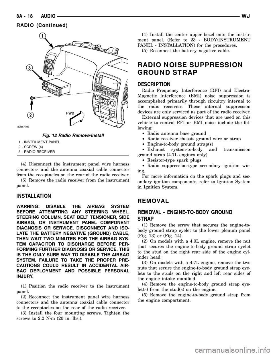
(4) Disconnect the instrument panel wire harness
connectors and the antenna coaxial cable connector
from the receptacles on the rear of the radio receiver.
(5) Remove the radio receiver from the instrument
panel.
INSTALLATION
WARNING: DISABLE THE AIRBAG SYSTEM
BEFORE ATTEMPTING ANY STEERING WHEEL,
STEERING COLUMN, SEAT BELT TENSIONER, SIDE
AIRBAG, OR INSTRUMENT PANEL COMPONENT
DIAGNOSIS OR SERVICE. DISCONNECT AND ISO-
LATE THE BATTERY NEGATIVE (GROUND) CABLE,
THEN WAIT TWO MINUTES FOR THE AIRBAG SYS-
TEM CAPACITOR TO DISCHARGE BEFORE PER-
FORMING FURTHER DIAGNOSIS OR SERVICE. THIS
IS THE ONLY SURE WAY TO DISABLE THE AIRBAG
SYSTEM. FAILURE TO TAKE THE PROPER PRE-
CAUTIONS COULD RESULT IN ACCIDENTAL AIR-
BAG DEPLOYMENT AND POSSIBLE PERSONAL
INJURY.
(1) Position the radio receiver to the instrument
panel.
(2) Reconnect the instrument panel wire harness
connectors and the antenna coaxial cable connector
to the receptacles on the rear of the radio receiver.
(3) Install the four mounting screws. Tighten the
screws to 2.2 N´m (20 in. lbs.).(4) Install the center upper bezel onto the instru-
ment panel. (Refer to 23 - BODY/INSTRUMENT
PANEL - INSTALLATION) for the procedures.
(5) Reconnect the battery negative cable.
RADIO NOISE SUPPRESSION
GROUND STRAP
DESCRIPTION
Radio Frequency Interference (RFI) and Electro-
Magnetic Interference (EMI) noise suppression is
accomplished primarily through circuitry internal to
the radio receivers. These internal suppression
devices are only serviced as part of the radio receiver.
External suppression devices that are used on this
vehicle to control RFI or EMI noise include the fol-
lowing:
²Radio antenna base ground
²Radio receiver chassis ground wire or strap
²Engine-to-body ground strap(s)
²Exhaust system-to-body and transmission
ground strap (4.7L engines only)
²Resistor-type spark plugs
²Radio suppression-type secondary ignition wir-
ing.
For more information on the spark plugs and sec-
ondary ignition components, refer to Ignition System
in Ignition System.
REMOVAL
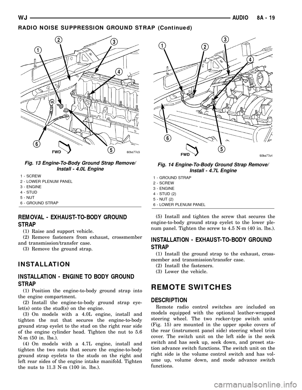
REMOVAL - ENGINE-TO-BODY GROUND
STRAP
(1) Remove the screw that secures the engine-to-
body ground strap eyelet to the lower plenum panel
(Fig. 13) or (Fig. 14).
(2) On models with a 4.0L engine, remove the nut
that secures the engine-to-body ground strap eyelet
to the stud on the right rear side of the engine cyl-
inder head.
(3) On models with a 4.7L engine, remove the two
nuts that secure the engine-to-body ground strap eye-
lets to the studs on the right and left rear sides of
the engine intake manifold.
(4) Remove the engine-to-body ground strap eye-
let(s) from the stud(s) on the engine.
(5) Remove the engine-to-body ground strap from
the engine compartment.
Fig. 12 Radio Remove/Install
1 - INSTRUMENT PANEL
2 - SCREW (4)
3 - RADIO RECEIVER
8A - 18 AUDIOWJ
RADIO (Continued)
Page 298 of 2199
REMOVAL - EXHAUST-TO-BODY GROUND
STRAP
(1) Raise and support vehicle.
(2) Remove fasteners from exhaust, crossmember
and transmission/transfer case.
(3) Remove the ground strap.
INSTALLATION
INSTALLATION - ENGINE TO BODY GROUND
STRAP
(1) Position the engine-to-body ground strap into
the engine compartment.
(2) Install the engine-to-body ground strap eye-
let(s) onto the stud(s) on the engine.
(3) On models with a 4.0L engine, install and
tighten the nut that secures the engine-to-body
ground strap eyelet to the stud on the right rear side
of the engine cylinder head. Tighten the nut to 5.6
N´m (50 in. lbs.).
(4) On models with a 4.7L engine, install and
tighten the two nuts that secure the engine-to-body
ground strap eyelets to the studs on the right and
left rear sides of the engine intake manifold. Tighten
the nuts to 11.3 N´m (100 in. lbs.).(5) Install and tighten the screw that secures the
engine-to-body ground strap eyelet to the lower ple-
num panel. Tighten the screw to 4.5 N´m (40 in. lbs.).
INSTALLATION - EXHAUST-TO-BODY GROUND
STRAP
(1) Install the ground strap to the exhaust, cross-
member and transmission/transfer case.
(2) Install the fasteners.
(3) Lower the vehicle.
REMOTE SWITCHES
DESCRIPTION
Remote radio control switches are included on
models equipped with the optional leather-wrapped
steering wheel. The two rocker-type switch units
(Fig. 15) are mounted in the upper spoke covers of
the rear (instrument panel side) steering wheel trim
cover. The switch unit on the left side is the seek
switch and has seek up, seek down, and preset sta-
tion advance switch functions. The switch unit on the
right side is the volume control switch and has vol-
ume up, volume down, and mode advance switch
functions.
Fig. 13 Engine-To-Body Ground Strap Remove/
Install - 4.0L Engine
1 - SCREW
2 - LOWER PLENUM PANEL
3 - ENGINE
4 - STUD
5 - NUT
6 - GROUND STRAP
Fig. 14 Engine-To-Body Ground Strap Remove/
Install - 4.7L Engine
1 - GROUND STRAP
2 - SCREW
3 - ENGINE
4 - STUD (2)
5 - NUT (2)
6 - LOWER PLENUM PANEL
WJAUDIO 8A - 19
RADIO NOISE SUPPRESSION GROUND STRAP (Continued)
Page 610 of 2199
²Front Check Valve- The front washer system
check valve is integral to the wye fitting located in
the washer plumbing between the cowl plenum
washer hose and the front washer nozzles, and is
concealed beneath the cowl plenum cover/grille panel
at the base of the windshield.
²Front Washer Nozzle- Two fluidic front
washer nozzles are secured with integral snap fea-
tures to dedicated openings in the cowl plenum cover/
grille panel located near the base of the windshield.
²Front Washer Plumbing- The plumbing for
the front washer system consists of rubber hoses and
molded plastic fittings. The plumbing is routed along
the left side of the engine compartment from the
washer reservoir, and through the dash panel into
the cowl plenum to the front washer nozzle fittings
beneath the cowl plenum cover/grille panel.
²Front Washer Pump/Motor- The front washer
pump/motor unit is located in a dedicated hole on the
lower outboard side of the washer reservoir, behind
the inner fender liner ahead of the left front wheel.
The front washer pump is located ahead of and below
the rear washer pump.
²Front Wiper Arm- The two front wiper arms
are secured with nuts to the threaded studs on the
ends of the two wiper pivot shafts, which extend
through the cowl plenum cover/grille panel located
near the base of the windshield.
²Front Wiper Blade- The two front wiper
blades are secured to the two front wiper arms with
an integral latch, and are parked on the glass near
the bottom of the windshield when the front wiper
system is not in operation.
²Front Wiper Module- The front wiper pivot
shafts are the only visible components of the front
wiper module. The remainder of the module is con-
cealed within the cowl plenum beneath the cowl ple-
num cover/grille panel. The front wiper module
includes the module bracket, four rubber-isolated
wiper module mounts, the front wiper motor, the
wiper motor crank arm, the two wiper drive links,
and the two front wiper pivots.
²Rain Sensor Module- Models equipped with
the optional automatic wiper feature have a Rain
Sensor Module (RSM) located behind a trim cover on
a bracket bonded to the inside surface of the wind-
shield glass, just above the inside rear view mirror
mounting button.
²Right Multi-Function Switch- The right
(wiper) multi-function switch is secured to the right
side of the multi-function switch mounting housing
near the top of the steering column, just below the
steering wheel. Only the control stalk for the right
multi-function switch is visible, while the remainder
of the switch is concealed beneath the steering col-
umn shrouds. The right multi-function switch con-tains all of the switches and control circuitry for both
the front and rear wiper and washer systems.
²Washer Fluid Level Switch- The washer fluid
level switch is located in a dedicated hole near the
center of the forward surface of the washer reservoir,
behind the left front wheel house splash shield.
²Washer Reservoir- The washer reservoir is
concealed between the left inner fender shield and
the left outer fender panel, behind the inner fender
liner and ahead of the left front wheel. The washer
reservoir filler neck is the only visible portion of the
reservoir, and it is accessed from the left front corner
of the engine compartment.
²Wiper High-Low Relay- The wiper high-low
relay is an International Standards Organization
(ISO) micro relay located in the Power Distribution
Center (PDC) in the engine compartment near the
battery.
²Wiper On-Off Relay- The wiper on-off relay is
an International Standards Organization (ISO) micro
relay located in the Power Distribution Center (PDC)
in the engine compartment near the battery.
Hard wired circuitry connects the front wiper and
washer system components to the electrical system of
the vehicle. These hard wired circuits are integral to
several wire harnesses, which are routed throughout
the vehicle and retained by many different methods.
These circuits may be connected to each other, to the
vehicle electrical system and to the front wiper and
washer system components through the use of a com-
bination of soldered splices, splice block connectors,
and many different types of wire harness terminal
connectors and insulators. Refer to the appropriate
wiring information. The wiring information includes
wiring diagrams, proper wire and connector repair
procedures, further details on wire harness routing
and retention, as well as pin-out and location views
for the various wire harness connectors, splices and
grounds.
OPERATING MODES
The components of the front wiper and washer sys-
tem are designed to work in concert to provide the
following operating modes:
²Automatic Wiper- In models equipped with
the optional automatic wiper feature, the internal
circuitry of both the right (wiper) multi-function
switch, the rain sensor module, and the BCM work
in concert to provide an automatic wiper mode with
five sensitivity selections. The BCM tells the Rain
Sensor Module (RSM) when the automatic wiper
mode is selected and the manually selected sensitiv-
ity level, then the rain sensor module tells the BCM
each time enough water droplets have accumulated
within the wipe pattern on the windshield to require
front wiper operation. The BCM then automatically
WJFRONT WIPERS/WASHERS 8R - 3
FRONT WIPERS/WASHERS (Continued)
Page 616 of 2199
WASHER SYSTEM
The washer system components should be
inspected periodically, not just when washer perfor-
mance problems are experienced. This inspection
should include the following points:
(1) Check for ice or other foreign material in the
washer reservoir. If contaminated, clean and flush
the washer system. (Refer to 8 - ELECTRICAL/
FRONT WIPERS/WASHERS - CLEANING).
(2) Inspect the washer plumbing for pinched, leak-
ing, deteriorated, or incorrectly routed hoses and
damaged or disconnected hose fittings. Replace dam-
aged or deteriorated hoses and hose fittings. Leaking
washer hoses can sometimes be repaired by cutting
the hose at the leak and splicing it back together
using an in-line connector fitting. Similarly, sections
of deteriorated hose can be cut out and replaced by
splicing in new sections of hose using in-line connec-
tor fittings. Whenever routing a washer hose or a
wire harness containing a washer hose, it must be
routed away from hot, sharp, or moving parts. Also,
sharp bends that might pinch the washer hose must
be avoided.
FRONT CHECK VALVE
DESCRIPTION
A front washer system check valve is standard
equipment on this model. The front check valve is
integral to the front washer nozzle plumbing wye fit-
ting located in the cowl plenum beneath the cowl ple-
num cover/grille panel near the base of the
windshield. The check valve consists of a molded
plastic body with a round center section. Three
barbed hose nipples are formed in a wye configura-
tion on the outside circumference of the center sec-
tion of the valve body. Within the check valve body, a
small check valve operated by a small coiled spring
restricts flow through the unit until the valve is
unseated by a predetermined inlet fluid pressure.
The front check valve cannot be adjusted or repaired
and, if faulty or damaged, it must be replaced.
OPERATION
The front check valve provides more than one func-
tion in this application. It serves as a wye connector
fitting between the cowl grille panel and washer noz-
zle sections of the front washer supply hose. It also
prevents washer fluid from draining out of the front
washer supply hoses back to the washer reservoir.
This drain-back would result in a lengthy delay from
when the front washer switch is actuated until
washer fluid was dispensed through the front washer
nozzles, because the front washer pump would have
to refill the front washer plumbing from the reservoir
to the nozzles. Finally, the front check valve prevents
washer fluid from siphoning through the front
washer nozzles after the front washer system is
turned Off. When the front washer pump pressurizes
and pumps washer fluid from the reservoir through
the front washer plumbing, the fluid pressure over-
rides the spring pressure applied to the check valve
and unseats the valve, allowing washer fluid to flow
toward the front washer nozzles. When the front
washer pump stops operating, spring pressure seats
the check valve and fluid flow in either direction
within the front washer plumbing is prevented.
REMOVAL
(1) Disconnect and isolate the battery negative
cable.
(2) Remove the wiper arms from the wiper pivots.
(Refer to 8 - ELECTRICAL/FRONT WIPERS/WASH-
ERS/FRONT WIPER ARMS - REMOVAL).
(3) Open the hood and pull the hood to plenum
seal off of the forward flanges of the cowl grille cover
and the plenum panel.
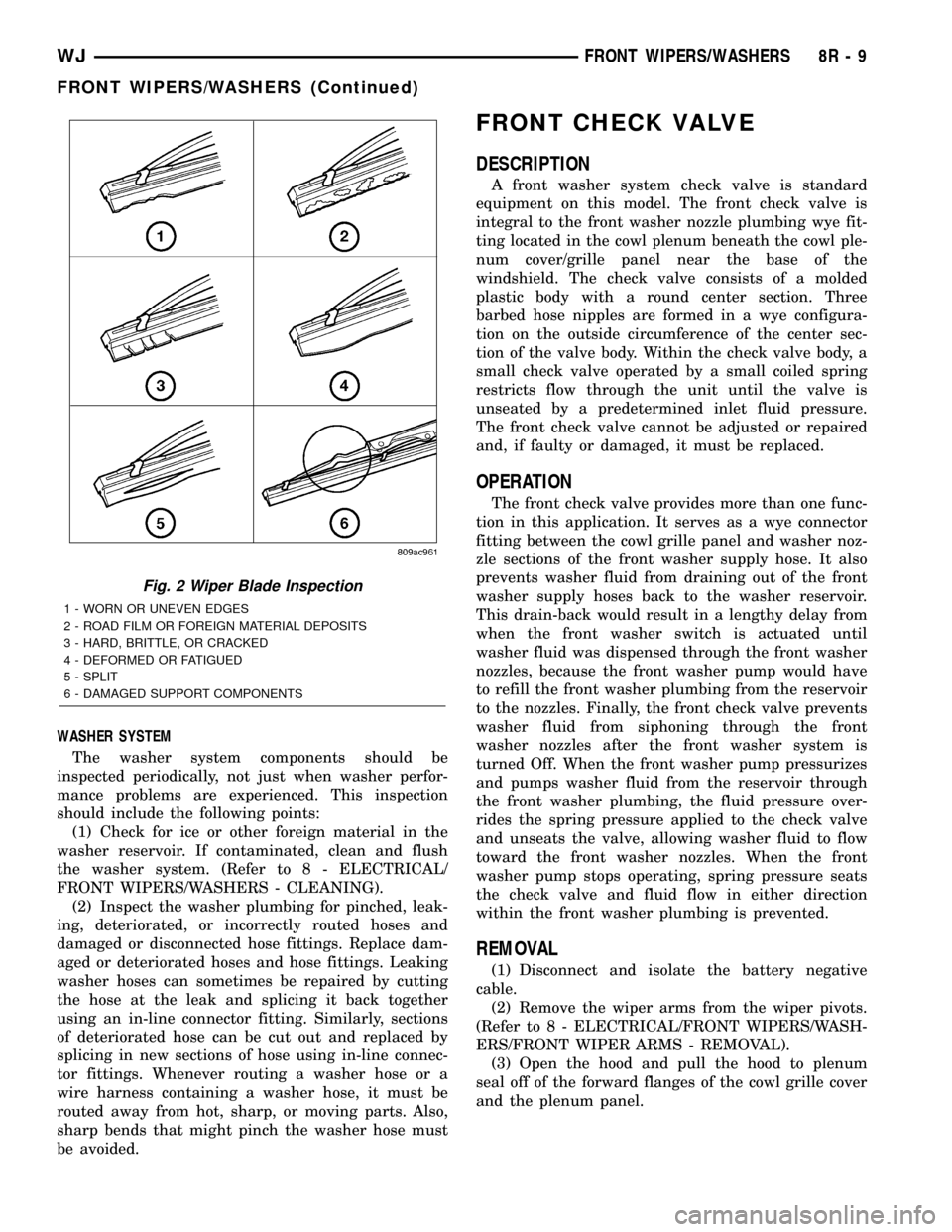
Fig. 2 Wiper Blade Inspection
1 - WORN OR UNEVEN EDGES
2 - ROAD FILM OR FOREIGN MATERIAL DEPOSITS
3 - HARD, BRITTLE, OR CRACKED
4 - DEFORMED OR FATIGUED
5 - SPLIT
6 - DAMAGED SUPPORT COMPONENTS
WJFRONT WIPERS/WASHERS 8R - 9
FRONT WIPERS/WASHERS (Continued)