rear suspension JEEP GRAND CHEROKEE 2002 WJ / 2.G Workshop Manual
[x] Cancel search | Manufacturer: JEEP, Model Year: 2002, Model line: GRAND CHEROKEE, Model: JEEP GRAND CHEROKEE 2002 WJ / 2.GPages: 2199, PDF Size: 76.01 MB
Page 1 of 2199
GROUP TAB LOCATOR
Introduction
0Lubrication & Maintenance
2Suspension
3Driveline
5Brakes
7Cooling
8AAudio
8BChime/Buzzer
8EElectronic Control Modules
8FEngine Systems
8GHeated Systems
8HHorn
8IIgnition Control
8JInstrument Cluster
8LLamps
8MMessage Systems
8NPower Systems
8ORestraints
8PSpeed Control
8QVehicle Theft Security
8RWipers/Washers
8WWiring
9Engine
11Exhaust System
13Frame & Bumpers
14Fuel System
19Steering
21Transaxle
22Tires/Wheels
23Body
24Heating & Air Conditioning
25Emissions Control
Service Manual Comment Forms (Rear of Manual)
Page 17 of 2199
DESCRIPTION - ENGINE OIL - DIESEL
ENGINES
Use only Diesel Engine Oil meeting standardMIL-
2104Cor API ClassificationCD or higherorCCML
D4, D5.
SAE VISCOSITY GRADE
CAUTION: Low viscosity oils must have the proper
API quality or the CCMC G5 designation.
To assure of properly formulated engine oils, it is
recommended that SAE Grade 10W-40 engine oils
that meet Chrysler material standard MS-6395, be
used. European Grade 10W-40 oils are also accept-
able.
Oils of the SAE 5W-40 or 8W-80 grade number are
preferred when minimum temperatures consistently
fall below -12ÉC.
OPERATION - AUTOMATIC TRANSMISSION
FLUID
The automatic transmission fluid is selected based
upon several qualities. The fluid must provide a high
level of protection for the internal components by
providing a lubricating film between adjacent metal
components. The fluid must also be thermally stable
so that it can maintain a consistent viscosity through
a large temperature range. If the viscosity stays con-
stant through the temperature range of operation,
transmission operation and shift feel will remain con-
sistent. Transmission fluid must also be a good con-
ductor of heat. The fluid must absorb heat from the
internal transmission components and transfer that
heat to the transmission case.
FLUID FILL/CHECK
LOCATIONS
INSPECTION - FLUID FILL/CHECK LOCATIONS
The fluid fill/check locations and lubrication points
are located in each applicable group.
MAINTENANCE SCHEDULES
DESCRIPTION
9Maintenance Schedule Information not included in
this section, is located in the appropriate Owner's
Manual.9
LIFT POINTS
STANDARD PROCEDURE - HOISTING AND
JACKING RECOMMENDATIONS
FLOOR JACK
When properly positioned, a floor jack can be used
to lift a WJ vehicle (Fig. 7). Support the vehicle in
the raised position with jack stands at the front and
rear ends of the frame rails.
CAUTION: Do not attempt to lift a vehicle with a
floor jack positioned under:
²An axle tube.
²Aluminum differential.
²A body side sill.
²A steering linkage component.
²A drive shaft.
²The engine or transmission oil pan.
²The fuel tank.
²A front suspension arm.
HOIST
A vehicle can be lifted with:
²A single-post, frame-contact hoist.
²A twin-post, chassis hoist.
²A ramp-type, drive-on hoist.
NOTE: When a frame-contact type hoist is used,
verify that the lifting pads are positioned properly
(Fig. 7).
WARNING: THE HOISTING AND JACK LIFTING
POINTS PROVIDED ARE FOR A COMPLETE VEHI-
CLE. WHEN A CHASSIS OR DRIVETRAIN COMPO-
NENT IS REMOVED FROM A VEHICLE, THE
CENTER OF GRAVITY IS ALTERED MAKING SOME
HOISTING CONDITIONS UNSTABLE. PROPERLY
SUPPORT OR SECURE VEHICLE TO HOISTING
DEVICE WHEN THESE CONDITIONS EXIST.
0 - 6 LUBRICATION & MAINTENANCEWJ
FLUID TYPES (Continued)
Page 22 of 2199
SUSPENSION
TABLE OF CONTENTS
page page
SUSPENSION
DIAGNOSIS AND TESTING - SUSPENSION
AND STEERING SYSTEM................1WHEEL ALIGNMENT......................3
FRONT.................................6
REAR.................................17
SUSPENSION
DIAGNOSIS AND TESTING - SUSPENSION AND
STEERING SYSTEM
CONDITION POSSIBLE CAUSES CORRECTION
FRONT END NOISE 1. Loose or worn wheel bearings. 1. Adjust or replace wheel bearings.
2. Loose or worn steering or
suspension components.2. Tighten or replace components as
necessary.
EXCESSIVE PLAY IN
STEERING1. Loose or worn wheel bearings. 1. Adjust or replace wheel bearings.
2. Loose or worn steering or
suspension components.2. Tighten or replace components as
necessary.
3. Loose or worn steering gear. 3. Adjust or replace steering gear.
FRONT WHEELS SHIMMY 1. Loose or worn wheel bearings. 1. Adjust or replace wheel bearings.
2. Loose or worn steering or
suspension components.2. Tighten or replace components as
necessary.
3. Tires worn or out of balance. 3. Replace or balance tires.
4. Alignment. 4. Align vehicle to specifications.
5. Leaking steering dampener. 5. Replace steering dampener.
VEHICLE INSTABILITY 1. Loose or worn wheel bearings. 1. Adjust or replace wheel bearings.
2. Loose or worn steering or
suspension components.2. Tighten or replace components as
necessary.
3. Tire pressure. 3. Adjust tire pressure.
4. Alignment. 4. Align vehicle to specifications.
EXCESSIVE STEERING
EFFORT1. Loose or worn steering gear. 1. Adjust or replace steering gear.
2. Power steering fluid low. 2. Add fluid and repair leak.
3. Column coupler binding. 3. Replace coupler.
4. Tire pressure. 4. Adjust tire pressure.
5. Alignment. 5. Align vehicle to specifications.
WJSUSPENSION 2 - 1
Page 24 of 2199
WHEEL ALIGNMENT
TABLE OF CONTENTS
page page
WHEEL ALIGNMENT
DESCRIPTION..........................3
OPERATION............................3
STANDARD PROCEDURE
STANDARD PROCEDURE - CAMBER.......3STANDARD PROCEDURE - CASTER.......4
STANDARD PROCEDURE - TOE POSITION . . 4
SPECIFICATIONS
ALIGNMENT..........................5
WHEEL ALIGNMENT
DESCRIPTION
Wheel alignment involves the correct positioning of
the wheels in relation to the vehicle. The positioning
is accomplished through suspension and steering
linkage adjustments. An alignment is considered
essential for efficient steering, good directional stabil-
ity and to minimize tire wear. The most important
measurements of an alignment are caster, camber
and toe position (Fig. 1).
CAUTION: Never attempt to modify suspension or
steering components by heating or bending.
CAUTION: Components attached with a nut and cot-
ter pin must be torqued to specification. Then if the
slot in the nut does not line up with the cotter pin
hole, tighten nut until it is aligned. Never loosen the
nut to align the cotter pin hole.
NOTE: Periodic lubrication of the front suspension/
steering system components may be required. Rub-
ber bushings must never be lubricated, Refer to
Lubrication And Maintenance for the recommended
maintenance schedule.
OPERATION
²CASTERis the forward or rearward tilt of the
steering knuckle from vertical. Tilting the top of the
knuckle rearward provides positive caster. Tilting the
top of the knuckle forward provides negative caster.
Caster is a directional stability angle. This angle
enables the front wheels to return to a straight
ahead position after turns (Fig. 1).
²CAMBERis the inward or outward tilt of the
wheel relative to the center of the vehicle. Tilting the
top of the wheel inward provides negative camber.
Tilting the top of the wheel outward provides positive
camber. Incorrect camber will cause wear on theinside or outside edge of the tire. The angle is not
adjustable, damaged component(s) must be replaced
to correct the camber angle (Fig. 1).
²WHEEL TOE POSITIONis the difference
between the leading inside edges and trailing inside
edges of the front tires. Incorrect wheel toe position
is the most common cause of unstable steering and
uneven tire wear. The wheel toe position is thefinal
front wheel alignment adjustment (Fig. 1).
²STEERING AXIS INCLINATION ANGLEis
measured in degrees and is the angle that the steer-
ing knuckles are tilted. The inclination angle has a
fixed relationship with the camber angle. It will not
change except when a spindle or ball stud is dam-
aged or bent. The angle is not adjustable, damaged
component(s) must be replaced to correct the steering
axis inclination angle.
²THRUST ANGLEis the angle of the rear axle
relative to the centerline of the vehicle. Incorrect
thrust angle can cause off-center steering and exces-
sive tire wear. This angle is not adjustable, damaged
component(s) must be replaced to correct the thrust
angle (Fig. 1).
STANDARD PROCEDURE
STANDARD PROCEDURE - CAMBER
Before each alignment reading the vehicle should
be jounced (rear first, then front). Grasp each
bumper at the center and jounce the vehicle up and
down three times. Always release the bumper in the
down position.
To obtain an accurate alignment, a 4 wheel align-
ment machine must be used and the equipment cali-
bration verified.
The wheel camber angle is preset. This angle is not
adjustable and cannot be altered.
WJWHEEL ALIGNMENT 2 - 3
Page 26 of 2199
NOTE: Make sure the toe setting does not change
during clamp tightening.
(6) Verify alignment specifications, then turn the
engine off.
STEERING WHEEL CENTERING
NOTE: The steering wheel can be centered without
affecting the toe position.
(1) Loosen the drag link adjustment sleeve clamp
bolts.
(2) Turn the adjustment sleeve to center the
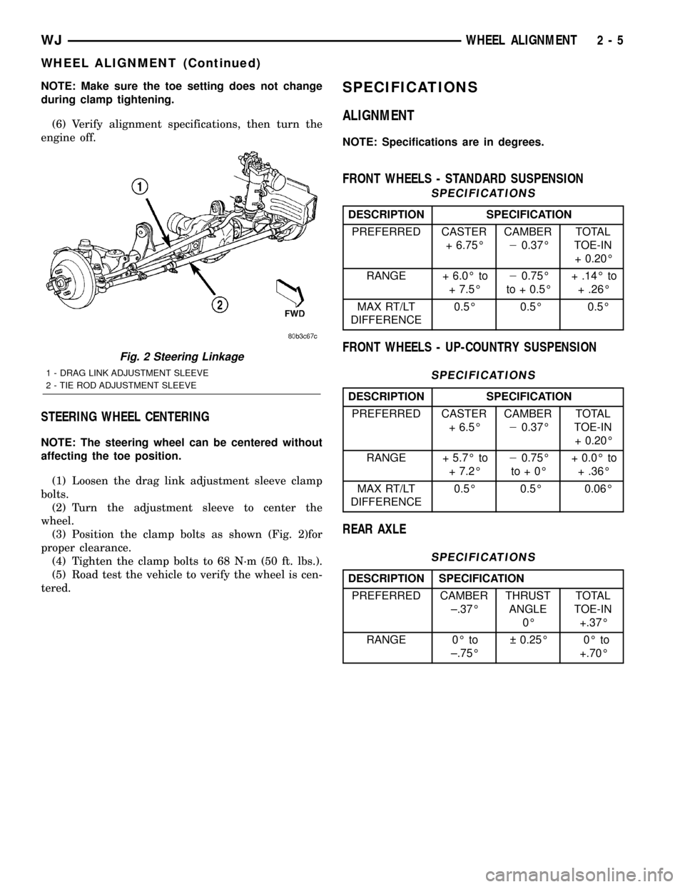
wheel.
(3) Position the clamp bolts as shown (Fig. 2)for
proper clearance.
(4) Tighten the clamp bolts to 68 N´m (50 ft. lbs.).
(5) Road test the vehicle to verify the wheel is cen-
tered.
SPECIFICATIONS
ALIGNMENT
NOTE: Specifications are in degrees.
FRONT WHEELS - STANDARD SUSPENSION
SPECIFICATIONS
DESCRIPTION SPECIFICATION
PREFERRED CASTER
+ 6.75ÉCAMBER
20.37ÉTOTAL
TOE-IN
+ 0.20É
RANGE + 6.0É to
+ 7.5É20.75É
to + 0.5É+ .14É to
+ .26É
MAX RT/LT
DIFFERENCE0.5É 0.5É 0.5É
FRONT WHEELS - UP-COUNTRY SUSPENSION
SPECIFICATIONS
DESCRIPTION SPECIFICATION
PREFERRED CASTER
+ 6.5ÉCAMBER
20.37ÉTOTAL
TOE-IN
+ 0.20É
RANGE + 5.7É to
+ 7.2É20.75É
to+0É+ 0.0É to
+ .36É
MAX RT/LT
DIFFERENCE0.5É 0.5É 0.06É
REAR AXLE
SPECIFICATIONS
DESCRIPTION SPECIFICATION
PREFERRED CAMBER
±.37ÉTHRUST
ANGLE
0ÉTOTAL
TOE-IN
+.37É
RANGE 0É to
±.75É 0.25É 0É to
+.70É
Fig. 2 Steering Linkage
1 - DRAG LINK ADJUSTMENT SLEEVE
2 - TIE ROD ADJUSTMENT SLEEVE
WJWHEEL ALIGNMENT 2 - 5
WHEEL ALIGNMENT (Continued)
Page 38 of 2199
REAR
TABLE OF CONTENTS
page page
REAR
DESCRIPTION.........................17
WARNING.............................17
DIAGNOSIS AND TESTING - REAR
SUSPENSION........................18
SPECIFICATIONS
TORQUE CHART......................18
SPECIAL TOOLS
REAR SUSPENSION...................19
LOWER CONTROL ARM
DESCRIPTION.........................19
OPERATION...........................19
REMOVAL.............................19
INSTALLATION.........................19
SHOCK
DESCRIPTION.........................19
OPERATION...........................19
REMOVAL.............................19
INSTALLATION.........................19
SPRING
DESCRIPTION.........................20OPERATION...........................20
REMOVAL.............................20
INSTALLATION.........................20
STABILIZER BAR
DESCRIPTION.........................21
OPERATION...........................21
REMOVAL.............................21
INSTALLATION.........................21
UPPER BALL JOINT
DESCRIPTION - UPPER SUSPENSION ARM,
BUSHINGS, AND BALL JOINT............21
OPERATION - UPPER SUSPENSION ARM,
BUSHINGS, AND BALL JOINT............21
REMOVAL.............................21
INSTALLATION.........................22
UPPER CONTROL ARM
DESCRIPTION.........................22
OPERATION...........................22
REMOVAL.............................22
INSTALLATION.........................23
REAR
DESCRIPTION
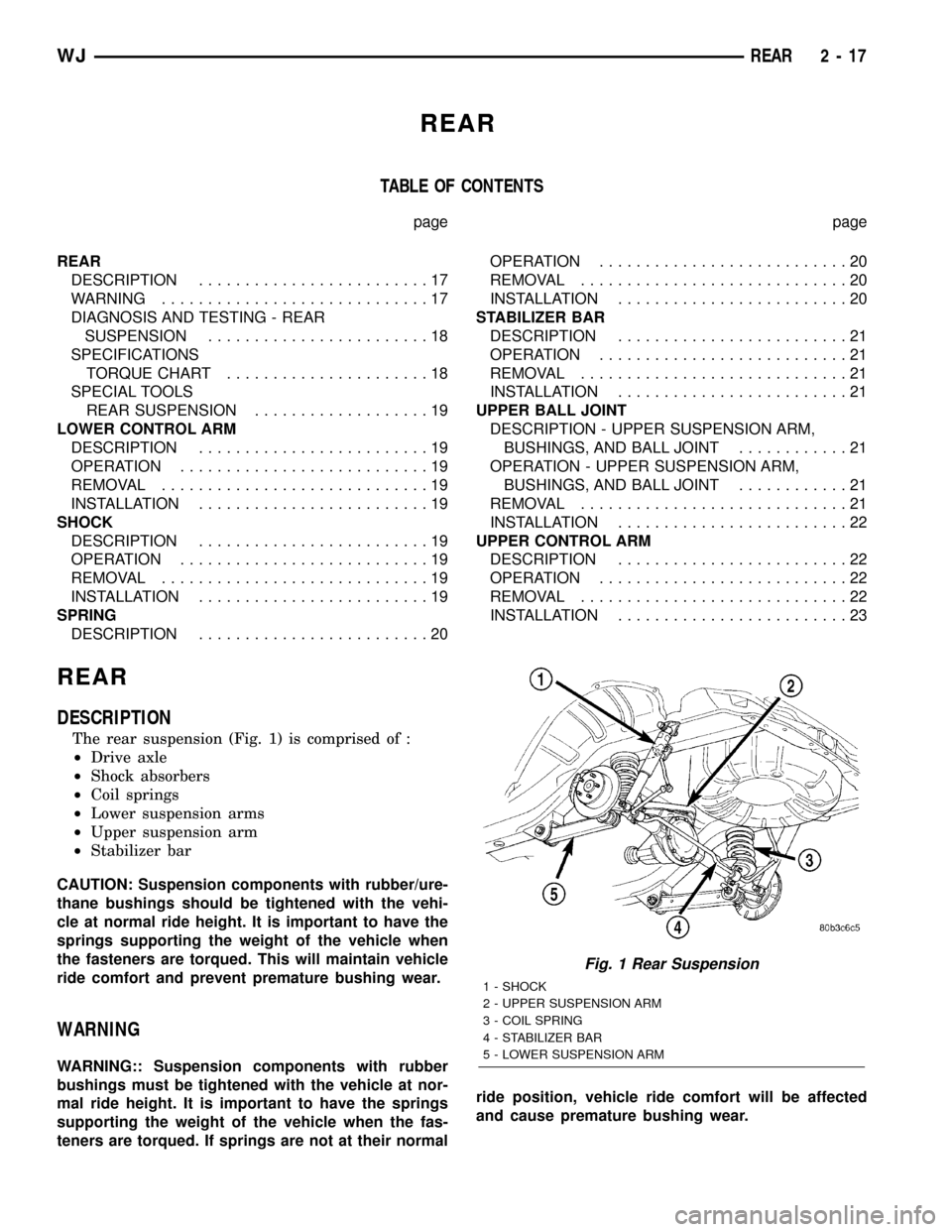
The rear suspension (Fig. 1) is comprised of :
²Drive axle
²Shock absorbers
²Coil springs
²Lower suspension arms
²Upper suspension arm
²Stabilizer bar
CAUTION: Suspension components with rubber/ure-
thane bushings should be tightened with the vehi-
cle at normal ride height. It is important to have the
springs supporting the weight of the vehicle when
the fasteners are torqued. This will maintain vehicle
ride comfort and prevent premature bushing wear.
WARNING
WARNING:: Suspension components with rubber
bushings must be tightened with the vehicle at nor-
mal ride height. It is important to have the springs
supporting the weight of the vehicle when the fas-
teners are torqued. If springs are not at their normalride position, vehicle ride comfort will be affected
and cause premature bushing wear.
Fig. 1 Rear Suspension
1 - SHOCK
2 - UPPER SUSPENSION ARM
3 - COIL SPRING
4 - STABILIZER BAR
5 - LOWER SUSPENSION ARM
WJREAR 2 - 17
Page 39 of 2199
DIAGNOSIS AND TESTING - REAR
SUSPENSION
CONDITION POSSIBLE CAUSES CORRECTION
VEHICLE INSTABILITY 1. Loose or worn wheel bearings. 1. Replace wheel bearings.
2. Loose, worn or bent suspension
components.2. Inspect, tighten or replace components
as necessary.
3. Tire pressure. 3. Adjust tire pressure.
VEHICLE PULLS TO ONE
SIDE1. Weak or broken spring. 1. Replace spring.
2. Alignment. 2. Align vehicle to specifications.
3.Tires. 3. Replace tires.
4. Brakes. 4. Repair as necassary.
KNOCKING, RATTLING
OR SQUEAKING1. Worn shock bushings. 1. Replace shock.
2. Loose shock mounting. 2. Tighten to specifications.
3. Shock valve. 3. Replace shock.
4. Loose upper ball joint. 4. Replace ball joint.
5. Loose, worn or bent suspension
components.5. Inspect, tighten or replace components
as necessary.
IMPROPER TRACKING 1. Loose, worn or bent suspension
components.1. Inspect, tighten or replace components
as necessary.
2. Bent axle. 2.Replace axle.
SPECIFICATIONS
TORQUE CHART
TORQUE SPECIFICATIONS
DESCRIPTION N´m Ft. Lbs. In. Lbs.
Shock Absorber Upper Nut 108 80 Ð
Shock Absorber Lower Nut 115 85 Ð
Suspension Arm Upper Ball Joint Nut 142 105 Ð
Suspension Arm Upper Frame Bolts 100 74 Ð
Ball Joint Plate Bolts 136 100 Ð
Suspension Arms Lower Axle Bracket Nut 163 120 Ð
Suspension Arms Lower Frame Bracket Nut 156 115 Ð
Stabilizer Bar Retainer Bolts 54 40 Ð
Stabilizer Bar Bar Link Nut 54 40 Ð
Stabilizer Bar Bracket Link Nut 92 68 Ð
2 - 18 REARWJ
REAR (Continued)
Page 40 of 2199
SPECIAL TOOLS
REAR SUSPENSION
LOWER CONTROL ARM
DESCRIPTION
The lower suspension arms are hydroformed steel
and use voided oval bushings at each end of the arm.
OPERATION
The bushings provide isolation from the axle. The
arms mount to the unibody frame rail bracket and
the axle brackets. The arm and bushings provide
location and react to loads.
REMOVAL
(1) Raise the vehicle and support the rear axle.
(2) Remove the lower suspension arm nut and bolt
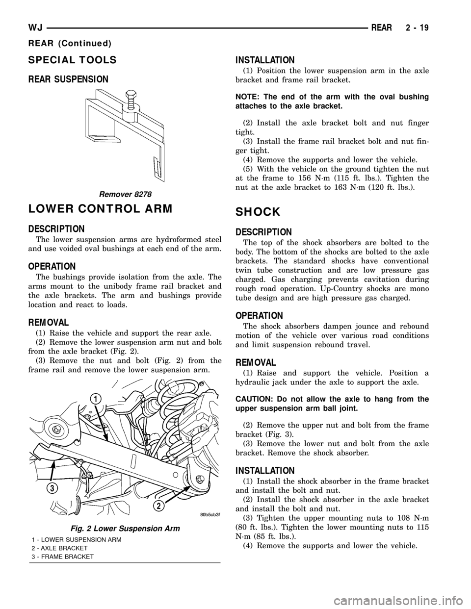
from the axle bracket (Fig. 2).
(3) Remove the nut and bolt (Fig. 2) from the
frame rail and remove the lower suspension arm.
INSTALLATION
(1) Position the lower suspension arm in the axle
bracket and frame rail bracket.
NOTE: The end of the arm with the oval bushing
attaches to the axle bracket.
(2) Install the axle bracket bolt and nut finger
tight.
(3) Install the frame rail bracket bolt and nut fin-
ger tight.
(4) Remove the supports and lower the vehicle.
(5) With the vehicle on the ground tighten the nut
at the frame to 156 N´m (115 ft. lbs.). Tighten the
nut at the axle bracket to 163 N´m (120 ft. lbs.).
SHOCK
DESCRIPTION
The top of the shock absorbers are bolted to the
body. The bottom of the shocks are bolted to the axle
brackets. The standard shocks have conventional
twin tube construction and are low pressure gas
charged. Gas charging prevents cavitation during
rough road operation. Up-Country shocks are mono
tube design and are high pressure gas charged.
OPERATION
The shock absorbers dampen jounce and rebound
motion of the vehicle over various road conditions
and limit suspension rebound travel.
REMOVAL
(1) Raise and support the vehicle. Position a
hydraulic jack under the axle to support the axle.
CAUTION: Do not allow the axle to hang from the
upper suspension arm ball joint.
(2) Remove the upper nut and bolt from the frame
bracket (Fig. 3).
(3) Remove the lower nut and bolt from the axle
bracket. Remove the shock absorber.
INSTALLATION
(1) Install the shock absorber in the frame bracket
and install the bolt and nut.
(2) Install the shock absorber in the axle bracket
and install the bolt and nut.
(3) Tighten the upper mounting nuts to 108 N´m
(80 ft. lbs.). Tighten the lower mounting nuts to 115
N´m (85 ft. lbs.).
(4) Remove the supports and lower the vehicle.
Remover 8278
Fig. 2 Lower Suspension Arm
1 - LOWER SUSPENSION ARM
2 - AXLE BRACKET
3 - FRAME BRACKET
WJREAR 2 - 19
REAR (Continued)
Page 42 of 2199
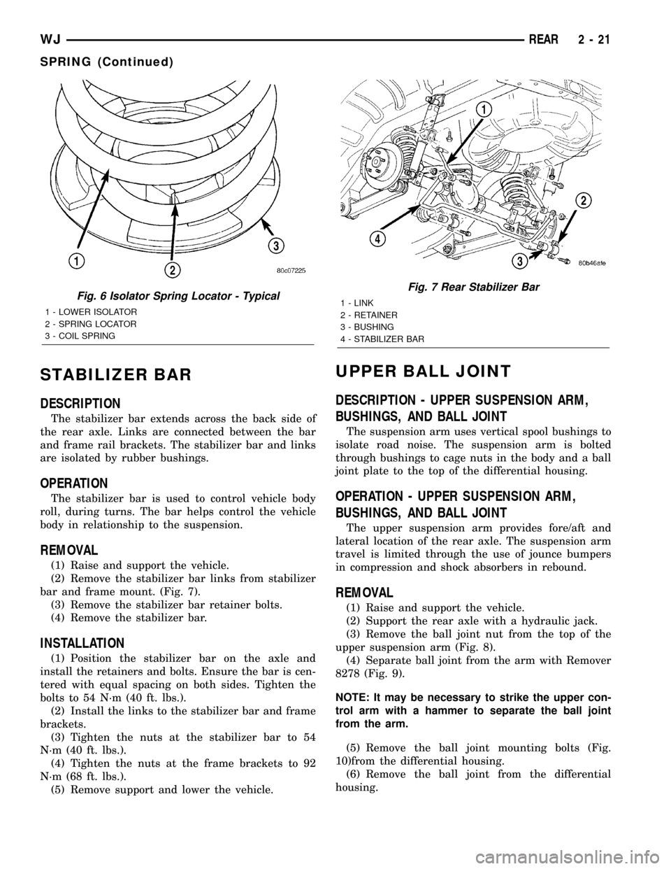
STABILIZER BAR
DESCRIPTION
The stabilizer bar extends across the back side of
the rear axle. Links are connected between the bar
and frame rail brackets. The stabilizer bar and links
are isolated by rubber bushings.
OPERATION
The stabilizer bar is used to control vehicle body
roll, during turns. The bar helps control the vehicle
body in relationship to the suspension.
REMOVAL
(1) Raise and support the vehicle.
(2) Remove the stabilizer bar links from stabilizer
bar and frame mount. (Fig. 7).
(3) Remove the stabilizer bar retainer bolts.
(4) Remove the stabilizer bar.
INSTALLATION
(1) Position the stabilizer bar on the axle and
install the retainers and bolts. Ensure the bar is cen-
tered with equal spacing on both sides. Tighten the
bolts to 54 N´m (40 ft. lbs.).
(2) Install the links to the stabilizer bar and frame
brackets.
(3) Tighten the nuts at the stabilizer bar to 54
N´m (40 ft. lbs.).
(4) Tighten the nuts at the frame brackets to 92
N´m (68 ft. lbs.).
(5) Remove support and lower the vehicle.
UPPER BALL JOINT
DESCRIPTION - UPPER SUSPENSION ARM,
BUSHINGS, AND BALL JOINT
The suspension arm uses vertical spool bushings to
isolate road noise. The suspension arm is bolted
through bushings to cage nuts in the body and a ball
joint plate to the top of the differential housing.
OPERATION - UPPER SUSPENSION ARM,
BUSHINGS, AND BALL JOINT
The upper suspension arm provides fore/aft and
lateral location of the rear axle. The suspension arm
travel is limited through the use of jounce bumpers
in compression and shock absorbers in rebound.
REMOVAL
(1) Raise and support the vehicle.
(2) Support the rear axle with a hydraulic jack.
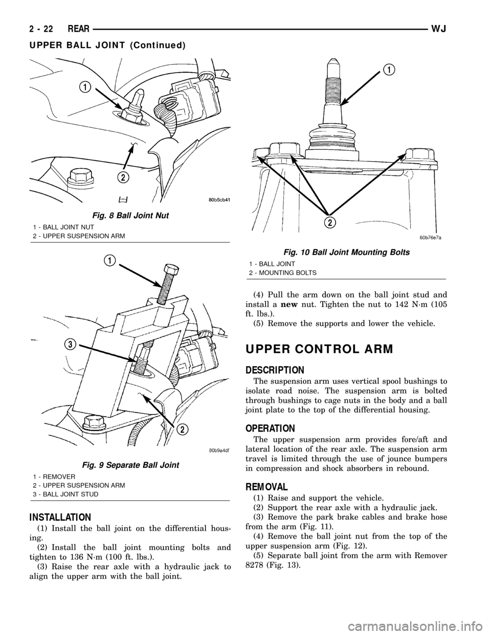
(3) Remove the ball joint nut from the top of the
upper suspension arm (Fig. 8).
(4) Separate ball joint from the arm with Remover
8278 (Fig. 9).
NOTE: It may be necessary to strike the upper con-
trol arm with a hammer to separate the ball joint
from the arm.
(5) Remove the ball joint mounting bolts (Fig.
10)from the differential housing.
(6) Remove the ball joint from the differential
housing.
Fig. 6 Isolator Spring Locator - Typical
1 - LOWER ISOLATOR
2 - SPRING LOCATOR
3 - COIL SPRING
Fig. 7 Rear Stabilizer Bar
1 - LINK
2 - RETAINER
3 - BUSHING
4 - STABILIZER BAR
WJREAR 2 - 21
SPRING (Continued)
Page 43 of 2199
INSTALLATION
(1) Install the ball joint on the differential hous-
ing.
(2) Install the ball joint mounting bolts and
tighten to 136 N´m (100 ft. lbs.).
(3) Raise the rear axle with a hydraulic jack to
align the upper arm with the ball joint.(4) Pull the arm down on the ball joint stud and
install anewnut. Tighten the nut to 142 N´m (105
ft. lbs.).
(5) Remove the supports and lower the vehicle.
UPPER CONTROL ARM
DESCRIPTION
The suspension arm uses vertical spool bushings to
isolate road noise. The suspension arm is bolted
through bushings to cage nuts in the body and a ball
joint plate to the top of the differential housing.
OPERATION
The upper suspension arm provides fore/aft and
lateral location of the rear axle. The suspension arm
travel is limited through the use of jounce bumpers
in compression and shock absorbers in rebound.
REMOVAL
(1) Raise and support the vehicle.
(2) Support the rear axle with a hydraulic jack.
(3) Remove the park brake cables and brake hose
from the arm (Fig. 11).
(4) Remove the ball joint nut from the top of the
upper suspension arm (Fig. 12).
(5) Separate ball joint from the arm with Remover
8278 (Fig. 13).
Fig. 8 Ball Joint Nut
1 - BALL JOINT NUT
2 - UPPER SUSPENSION ARM
Fig. 9 Separate Ball Joint
1 - REMOVER
2 - UPPER SUSPENSION ARM
3 - BALL JOINT STUD
Fig. 10 Ball Joint Mounting Bolts
1 - BALL JOINT
2 - MOUNTING BOLTS
2 - 22 REARWJ
UPPER BALL JOINT (Continued)