seat JEEP GRAND CHEROKEE 2002 WJ / 2.G Workshop Manual
[x] Cancel search | Manufacturer: JEEP, Model Year: 2002, Model line: GRAND CHEROKEE, Model: JEEP GRAND CHEROKEE 2002 WJ / 2.GPages: 2199, PDF Size: 76.01 MB
Page 5 of 2199
FASTENER USAGE
DESCRIPTION - FASTENER USAGE
WARNING: USE OF AN INCORRECT FASTENER
MAY RESULT IN COMPONENT DAMAGE OR PER-
SONAL INJURY.
Fasteners and torque specifications references in
this Service Manual are identified in metric and SAE
format.
During any maintenance or repair procedures, it is
important to salvage all fasteners (nuts, bolts, etc.)
for reassembly. If the fastener is not salvageable, a
fastener of equivalent specification must be used.
THREADED HOLE REPAIR
DESCRIPTION - THREADED HOLE REPAIR
Most stripped threaded holes can be repaired using
a Helicoilt. Follow the vehicle or Helicoiltrecommen-
dations for application and repair procedures.
INTERNATIONAL SYMBOLS
DESCRIPTION - INTERNATIONAL SYMBOLS
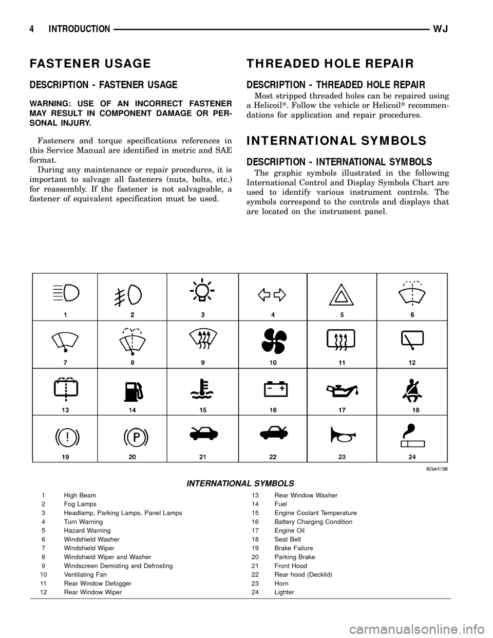
The graphic symbols illustrated in the following
International Control and Display Symbols Chart are
used to identify various instrument controls. The
symbols correspond to the controls and displays that
are located on the instrument panel.
INTERNATIONAL SYMBOLS
1 High Beam 13 Rear Window Washer
2 Fog Lamps 14 Fuel
3 Headlamp, Parking Lamps, Panel Lamps 15 Engine Coolant Temperature
4 Turn Warning 16 Battery Charging Condition
5 Hazard Warning 17 Engine Oil
6 Windshield Washer 18 Seat Belt
7 Windshield Wiper 19 Brake Failure
8 Windshield Wiper and Washer 20 Parking Brake
9 Windscreen Demisting and Defrosting 21 Front Hood
10 Ventilating Fan 22 Rear hood (Decklid)
11 Rear Window Defogger 23 Horn
12 Rear Window Wiper 24 Lighter
4 INTRODUCTIONWJ
Page 33 of 2199
SHOCK
DESCRIPTION
The top of the shock absorbers are bolted to the
body. The bottom of the shocks are bolted to the axle
brackets. The standard shocks have conventional
twin tube construction and are low pressure gas
charged. Gas charging prevents cavitation during
rough road operation. Up-Country shocks are mono
tube design and are high pressure gas charged.
OPERATION
The shock absorbers dampen jounce and rebound
motion of the vehicle over various road conditions
and limit suspension rebound travel.
REMOVAL
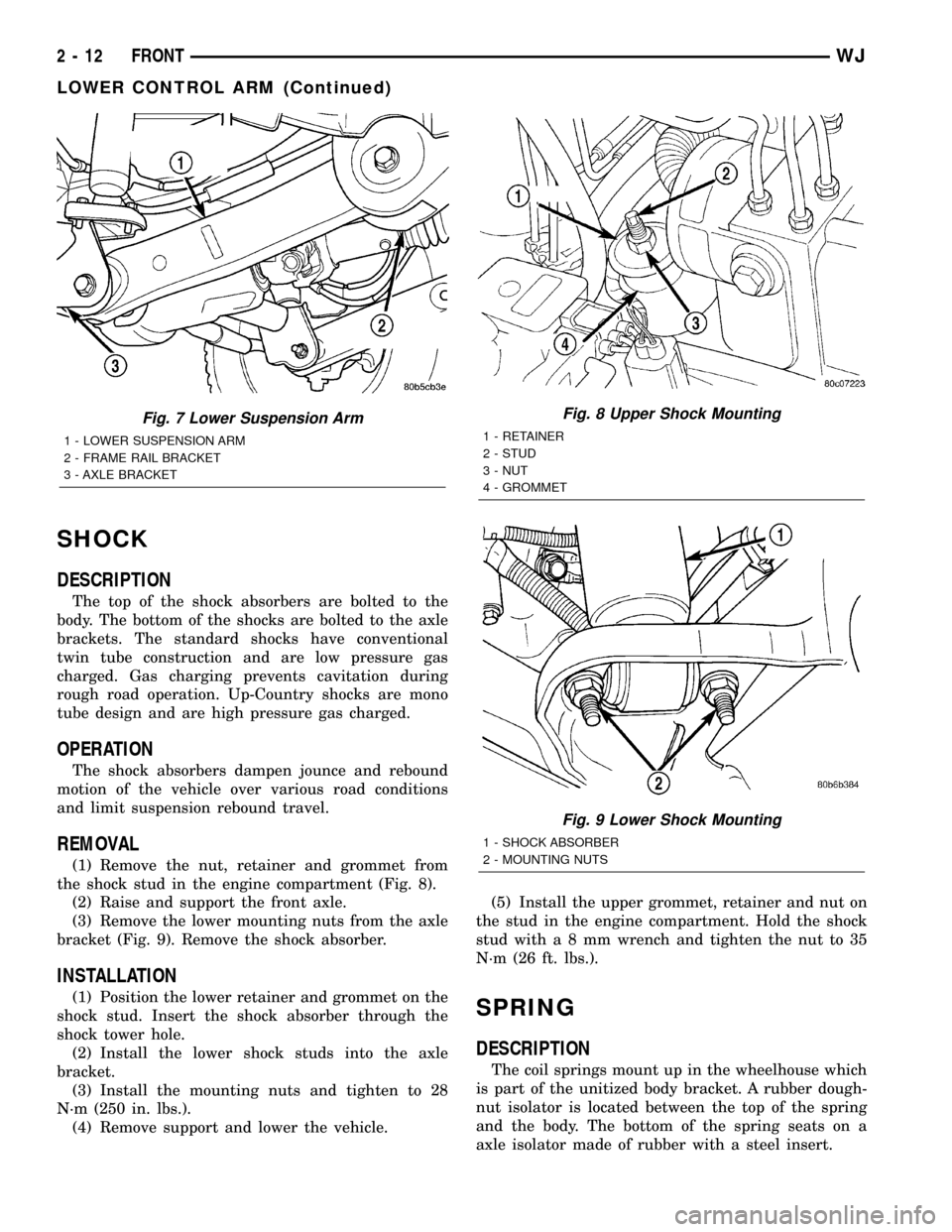
(1) Remove the nut, retainer and grommet from
the shock stud in the engine compartment (Fig. 8).
(2) Raise and support the front axle.
(3) Remove the lower mounting nuts from the axle
bracket (Fig. 9). Remove the shock absorber.
INSTALLATION
(1) Position the lower retainer and grommet on the
shock stud. Insert the shock absorber through the
shock tower hole.
(2) Install the lower shock studs into the axle
bracket.
(3) Install the mounting nuts and tighten to 28
N´m (250 in. lbs.).
(4) Remove support and lower the vehicle.(5) Install the upper grommet, retainer and nut on
the stud in the engine compartment. Hold the shock
stud witha8mmwrench and tighten the nut to 35
N´m (26 ft. lbs.).SPRING
DESCRIPTION
The coil springs mount up in the wheelhouse which
is part of the unitized body bracket. A rubber dough-
nut isolator is located between the top of the spring
and the body. The bottom of the spring seats on a
axle isolator made of rubber with a steel insert.
Fig. 7 Lower Suspension Arm
1 - LOWER SUSPENSION ARM
2 - FRAME RAIL BRACKET
3 - AXLE BRACKET
Fig. 8 Upper Shock Mounting
1 - RETAINER
2 - STUD
3 - NUT
4 - GROMMET
Fig. 9 Lower Shock Mounting
1 - SHOCK ABSORBER
2 - MOUNTING NUTS
2 - 12 FRONTWJ
LOWER CONTROL ARM (Continued)
Page 41 of 2199
SPRING
DESCRIPTION
The coil springs mount up in the wheelhouse which
is part of the unitized body bracket. A rubber dough-
nut isolator is located between the top of the spring
and the body. The bottom of the spring seats on a
axle isolator made of rubber with a steel insert. The
isolators provide road noise isolation
OPERATION
The coil springs control ride quality and maintain
proper ride height.
REMOVAL
(1) Raise and support the vehicle. Position a
hydraulic jack under the axle to support the axle.
(2) Remove the wheel and tire assemblies.
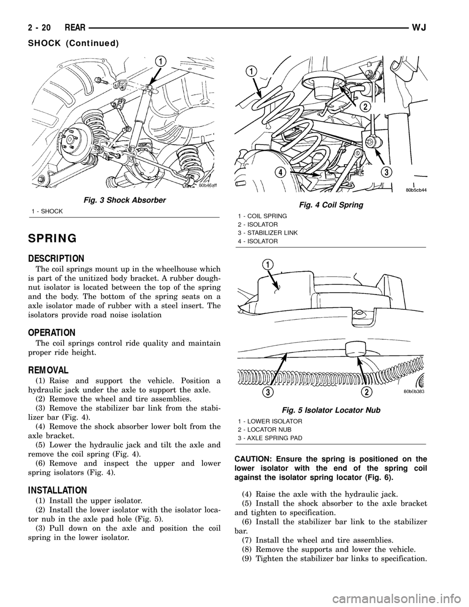
(3) Remove the stabilizer bar link from the stabi-
lizer bar (Fig. 4).
(4) Remove the shock absorber lower bolt from the
axle bracket.
(5) Lower the hydraulic jack and tilt the axle and
remove the coil spring (Fig. 4).
(6) Remove and inspect the upper and lower
spring isolators (Fig. 4).
INSTALLATION
(1) Install the upper isolator.
(2) Install the lower isolator with the isolator loca-
tor nub in the axle pad hole (Fig. 5).
(3) Pull down on the axle and position the coil
spring in the lower isolator.CAUTION: Ensure the spring is positioned on the
lower isolator with the end of the spring coil
against the isolator spring locator (Fig. 6).
(4) Raise the axle with the hydraulic jack.
(5) Install the shock absorber to the axle bracket
and tighten to specification.
(6) Install the stabilizer bar link to the stabilizer
bar.
(7) Install the wheel and tire assemblies.
(8) Remove the supports and lower the vehicle.
(9) Tighten the stabilizer bar links to specification.
Fig. 3 Shock Absorber
1 - SHOCKFig. 4 Coil Spring
1 - COIL SPRING
2 - ISOLATOR
3 - STABILIZER LINK
4 - ISOLATOR
Fig. 5 Isolator Locator Nub
1 - LOWER ISOLATOR
2 - LOCATOR NUB
3 - AXLE SPRING PAD
2 - 20 REARWJ
SHOCK (Continued)
Page 47 of 2199
DRIVELINE VIBRATION
Drive Condition Possible Cause Correction
Propeller Shaft Noise 1) Undercoating or other foreign material
on shaft.1) Clean exterior of shaft and wash with
solvent.
2) Loose U-joint clamp screws. 2) Install new clamps and screws and
tighten to proper torque.
3) Loose or bent U-joint yoke or
excessive runout.3) Install new yoke.
4) Incorrect driveline angularity. 4) Measure and correct driveline angles.
5) Rear spring center bolt not in seat. 5) Loosen spring u-bolts and seat center
bolt.
6) Worn U-joint bearings. 6) Install new U-joint.
7) Propeller shaft damaged or out of
balance.7) Installl new propeller shaft.
8) Broken rear spring. 8) Install new rear spring.
9) Excessive runout or unbalanced
condition.9) Re-index propeller shaft, test, and
evaluate.
10) Excessive drive pinion gear shaft
runout.10) Re-index propeller shaft and evaluate.
11) Excessive axle yoke deflection. 11) Inspect and replace yoke if necessary.
12) Excessive transfer case runout. 12) Inspect and repair as necessary.
Universal Joint Noise 1) Loose U-joint clamp screws. 1) Install new clamps and screws and
tighten to proper torque.
2) Lack of lubrication. 2) Replace U-joints as necessary.
BALANCE
NOTE: Removing and re-indexing the propeller
shaft 180É relative to the yoke may eliminate some
vibrations.
If propeller shaft is suspected of being unbalanced,
it can be verified with the following procedure:
(1) Raise the vehicle.
(2) Clean all the foreign material from the propel-
ler shaft and the universal joints.
(3) Inspect the propeller shaft for missing balance
weights, broken welds, and bent areas.If the pro-
peller shaft is bent, it must be replaced.
(4) Inspect the universal joints to ensure that they
are not worn, are properly installed, and are cor-
rectly aligned with the shaft.
(5) Check the universal joint clamp screws torque.
(6) Remove the wheels and tires. Install the wheel
lug nuts to retain the brake drums or rotors.
(7) Mark and number the shaft six inches from the
yoke end at four positions 90É apart.
(8) Run and accelerate the vehicle until vibration
occurs. Note the intensity and speed the vibration
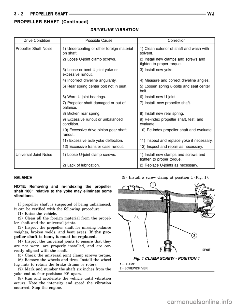
occurred. Stop the engine.(9) Install a screw clamp at position 1 (Fig. 1).
Fig. 1 CLAMP SCREW - POSITION 1
1 - CLAMP
2 - SCREWDRIVER
3 - 2 PROPELLER SHAFTWJ
PROPELLER SHAFT (Continued)
Page 54 of 2199
ASSEMBLY
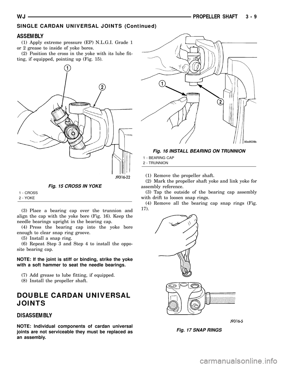
(1) Apply extreme pressure (EP) N.L.G.I. Grade 1
or 2 grease to inside of yoke bores.
(2) Position the cross in the yoke with its lube fit-
ting, if equipped, pointing up (Fig. 15).
(3) Place a bearing cap over the trunnion and
align the cap with the yoke bore (Fig. 16). Keep the
needle bearings upright in the bearing cap.
(4) Press the bearing cap into the yoke bore
enough to clear snap ring groove.
(5) Install a snap ring.
(6) Repeat Step 3 and Step 4 to install the oppo-
site bearing cap.
NOTE: If the joint is stiff or binding, strike the yoke
with a soft hammer to seat the needle bearings.
(7) Add grease to lube fitting, if equipped.
(8) Install the propeller shaft.
DOUBLE CARDAN UNIVERSAL
JOINTS
DISASSEMBLY
NOTE: Individual components of cardan universal
joints are not serviceable they must be replaced as
an assembly.(1) Remove the propeller shaft.
(2) Mark the propeller shaft yoke and link yoke for
assembly reference.
(3) Tap the outside of the bearing cap assembly
with drift to loosen snap rings.
(4) Remove all the bearing cap snap rings (Fig.
17).
Fig. 15 CROSS IN YOKE
1 - CROSS
2 - YOKE
Fig. 16 INSTALL BEARING ON TRUNNION
1 - BEARING CAP
2 - TRUNNION
Fig. 17 SNAP RINGS
WJPROPELLER SHAFT 3 - 9
SINGLE CARDAN UNIVERSAL JOINTS (Continued)
Page 57 of 2199
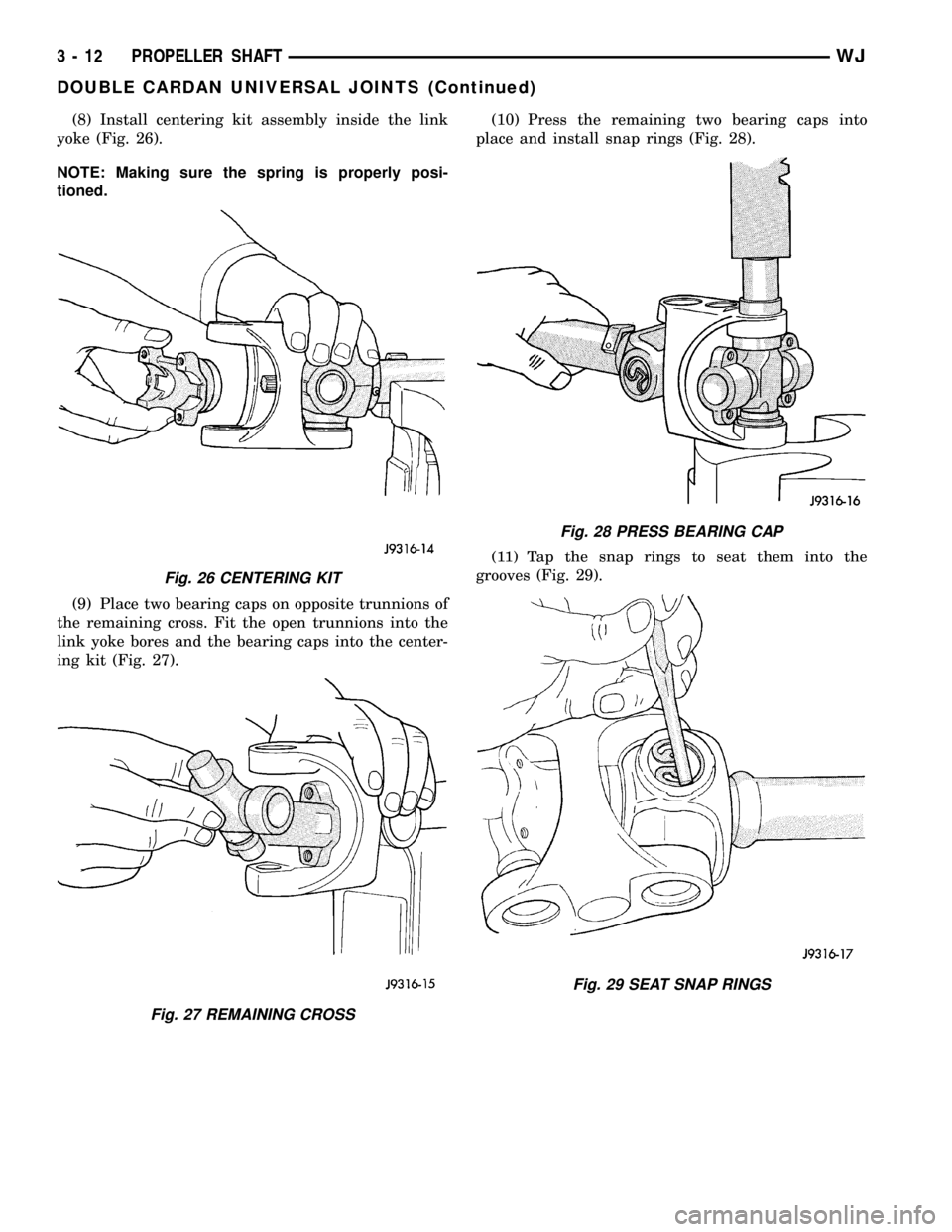
(8) Install centering kit assembly inside the link
yoke (Fig. 26).
NOTE: Making sure the spring is properly posi-
tioned.
(9) Place two bearing caps on opposite trunnions of
the remaining cross. Fit the open trunnions into the
link yoke bores and the bearing caps into the center-
ing kit (Fig. 27).(10) Press the remaining two bearing caps into
place and install snap rings (Fig. 28).
(11) Tap the snap rings to seat them into the
grooves (Fig. 29).
Fig. 26 CENTERING KIT
Fig. 27 REMAINING CROSS
Fig. 28 PRESS BEARING CAP
Fig. 29 SEAT SNAP RINGS
3 - 12 PROPELLER SHAFTWJ
DOUBLE CARDAN UNIVERSAL JOINTS (Continued)
Page 70 of 2199
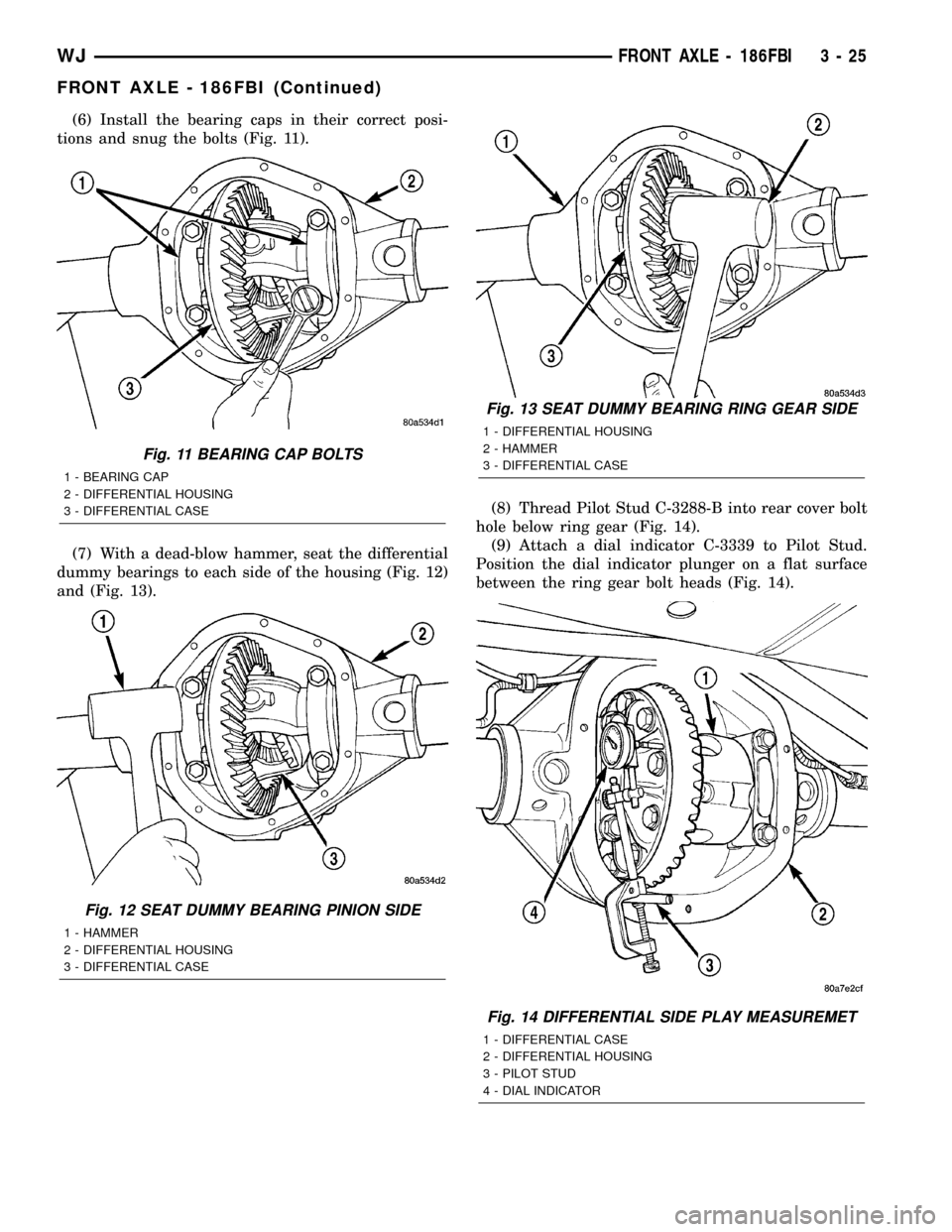
(6) Install the bearing caps in their correct posi-
tions and snug the bolts (Fig. 11).
(7) With a dead-blow hammer, seat the differential
dummy bearings to each side of the housing (Fig. 12)
and (Fig. 13).(8) Thread Pilot Stud C-3288-B into rear cover bolt
hole below ring gear (Fig. 14).
(9) Attach a dial indicator C-3339 to Pilot Stud.
Position the dial indicator plunger on a flat surface
between the ring gear bolt heads (Fig. 14).
Fig. 11 BEARING CAP BOLTS
1 - BEARING CAP
2 - DIFFERENTIAL HOUSING
3 - DIFFERENTIAL CASE
Fig. 12 SEAT DUMMY BEARING PINION SIDE
1 - HAMMER
2 - DIFFERENTIAL HOUSING
3 - DIFFERENTIAL CASE
Fig. 13 SEAT DUMMY BEARING RING GEAR SIDE
1 - DIFFERENTIAL HOUSING
2 - HAMMER
3 - DIFFERENTIAL CASE
Fig. 14 DIFFERENTIAL SIDE PLAY MEASUREMET
1 - DIFFERENTIAL CASE
2 - DIFFERENTIAL HOUSING
3 - PILOT STUD
4 - DIAL INDICATOR
WJFRONT AXLE - 186FBI 3 - 25
FRONT AXLE - 186FBI (Continued)
Page 71 of 2199
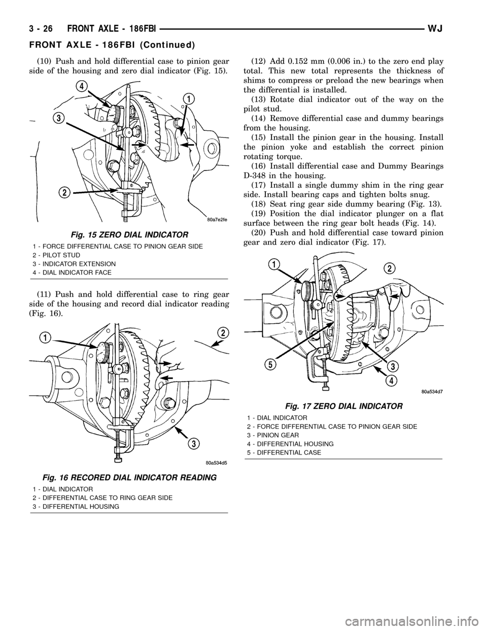
(10) Push and hold differential case to pinion gear
side of the housing and zero dial indicator (Fig. 15).
(11) Push and hold differential case to ring gear
side of the housing and record dial indicator reading
(Fig. 16).(12) Add 0.152 mm (0.006 in.) to the zero end play
total. This new total represents the thickness of
shims to compress or preload the new bearings when
the differential is installed.
(13) Rotate dial indicator out of the way on the
pilot stud.
(14) Remove differential case and dummy bearings
from the housing.
(15) Install the pinion gear in the housing. Install
the pinion yoke and establish the correct pinion
rotating torque.
(16) Install differential case and Dummy Bearings
D-348 in the housing.
(17) Install a single dummy shim in the ring gear
side. Install bearing caps and tighten bolts snug.
(18) Seat ring gear side dummy bearing (Fig. 13).
(19) Position the dial indicator plunger on a flat
surface between the ring gear bolt heads (Fig. 14).
(20) Push and hold differential case toward pinion
gear and zero dial indicator (Fig. 17).
Fig. 15 ZERO DIAL INDICATOR
1 - FORCE DIFFERENTIAL CASE TO PINION GEAR SIDE
2 - PILOT STUD
3 - INDICATOR EXTENSION
4 - DIAL INDICATOR FACE
Fig. 16 RECORED DIAL INDICATOR READING
1 - DIAL INDICATOR
2 - DIFFERENTIAL CASE TO RING GEAR SIDE
3 - DIFFERENTIAL HOUSING
Fig. 17 ZERO DIAL INDICATOR
1 - DIAL INDICATOR
2 - FORCE DIFFERENTIAL CASE TO PINION GEAR SIDE
3 - PINION GEAR
4 - DIFFERENTIAL HOUSING
5 - DIFFERENTIAL CASE
3 - 26 FRONT AXLE - 186FBIWJ
FRONT AXLE - 186FBI (Continued)
Page 72 of 2199
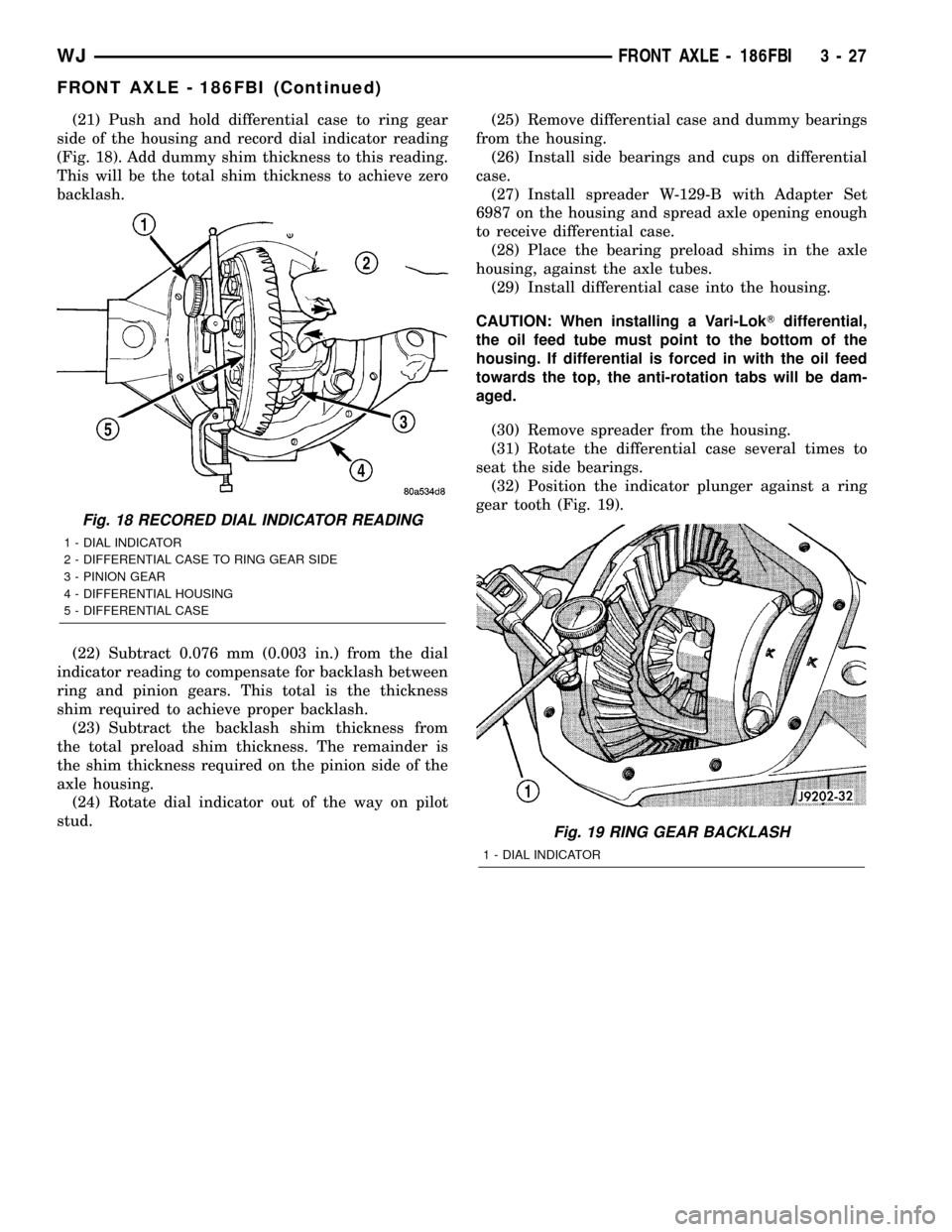
(21) Push and hold differential case to ring gear
side of the housing and record dial indicator reading
(Fig. 18). Add dummy shim thickness to this reading.
This will be the total shim thickness to achieve zero
backlash.
(22) Subtract 0.076 mm (0.003 in.) from the dial
indicator reading to compensate for backlash between
ring and pinion gears. This total is the thickness
shim required to achieve proper backlash.
(23) Subtract the backlash shim thickness from
the total preload shim thickness. The remainder is
the shim thickness required on the pinion side of the
axle housing.
(24) Rotate dial indicator out of the way on pilot
stud.(25) Remove differential case and dummy bearings
from the housing.
(26) Install side bearings and cups on differential
case.
(27) Install spreader W-129-B with Adapter Set
6987 on the housing and spread axle opening enough
to receive differential case.
(28) Place the bearing preload shims in the axle
housing, against the axle tubes.
(29) Install differential case into the housing.
CAUTION: When installing a Vari-LokTdifferential,
the oil feed tube must point to the bottom of the
housing. If differential is forced in with the oil feed
towards the top, the anti-rotation tabs will be dam-
aged.
(30) Remove spreader from the housing.
(31) Rotate the differential case several times to
seat the side bearings.
(32) Position the indicator plunger against a ring
gear tooth (Fig. 19).
Fig. 18 RECORED DIAL INDICATOR READING
1 - DIAL INDICATOR
2 - DIFFERENTIAL CASE TO RING GEAR SIDE
3 - PINION GEAR
4 - DIFFERENTIAL HOUSING
5 - DIFFERENTIAL CASE
Fig. 19 RING GEAR BACKLASH
1 - DIAL INDICATOR
WJFRONT AXLE - 186FBI 3 - 27
FRONT AXLE - 186FBI (Continued)
Page 88 of 2199
INSTALLATION
NOTE: If replacement differential bearings or differ-
ential case are being installed, differential side
bearing shim requirements may change. Refer to
Adjustments (Differential Bearing Preload and Gear
Backlash) to determine the proper shim selection.
(1) Position Spreader W-129-B with Adapter Kit
6987B on differential locating holes. Install hold
down clamps and tighten the tool turnbuckle finger-
tight.
(2) Install a Pilot Stud C-3288-B at the left side of
the differential housing. Attach Dial Indicator C-3339
to pilot stud. Load the indicator plunger against the
opposite side of the housing and zero the indicator.
(3) Spread the housing enough to install the case
in the housing. Measure the distance with the dial
indicator.
CAUTION: Never spread the housing over 0.50 mm
(0.020 in). If housing is over-spread, it could dis-
torted and damaged the housing.
(4) Remove the dial indicator.
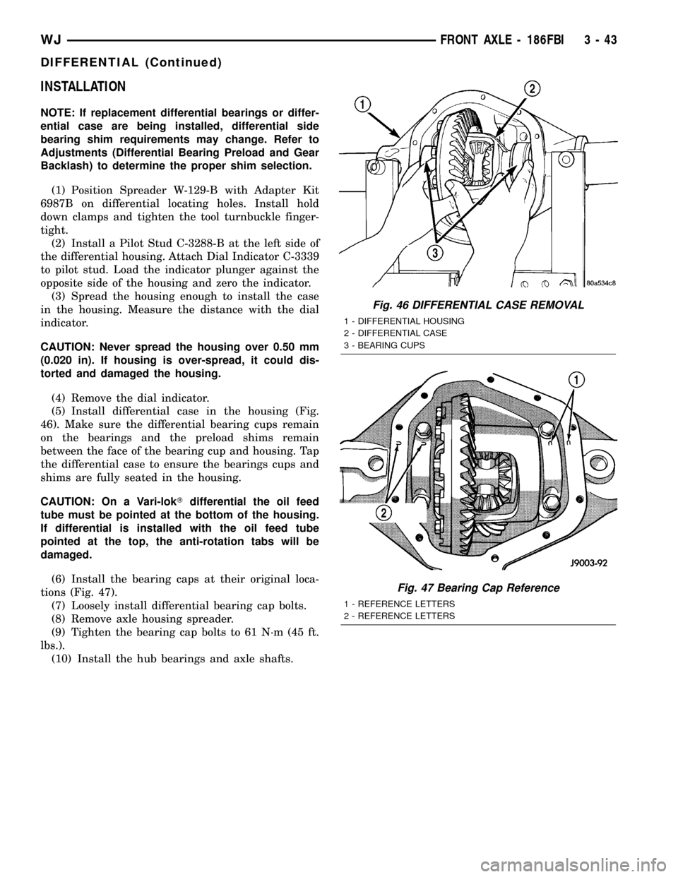
(5) Install differential case in the housing (Fig.
46). Make sure the differential bearing cups remain
on the bearings and the preload shims remain
between the face of the bearing cup and housing. Tap
the differential case to ensure the bearings cups and
shims are fully seated in the housing.
CAUTION: On a Vari-lokTdifferential the oil feed
tube must be pointed at the bottom of the housing.
If differential is installed with the oil feed tube
pointed at the top, the anti-rotation tabs will be
damaged.
(6) Install the bearing caps at their original loca-
tions (Fig. 47).
(7) Loosely install differential bearing cap bolts.
(8) Remove axle housing spreader.
(9) Tighten the bearing cap bolts to 61 N´m (45 ft.
lbs.).
(10) Install the hub bearings and axle shafts.
Fig. 46 DIFFERENTIAL CASE REMOVAL
1 - DIFFERENTIAL HOUSING
2 - DIFFERENTIAL CASE
3 - BEARING CUPS
Fig. 47 Bearing Cap Reference
1 - REFERENCE LETTERS
2 - REFERENCE LETTERS
WJFRONT AXLE - 186FBI 3 - 43
DIFFERENTIAL (Continued)