passenger side JEEP GRAND CHEROKEE 2003 WJ / 2.G Owners Manual
[x] Cancel search | Manufacturer: JEEP, Model Year: 2003, Model line: GRAND CHEROKEE, Model: JEEP GRAND CHEROKEE 2003 WJ / 2.GPages: 2199, PDF Size: 76.01 MB
Page 1104 of 2199
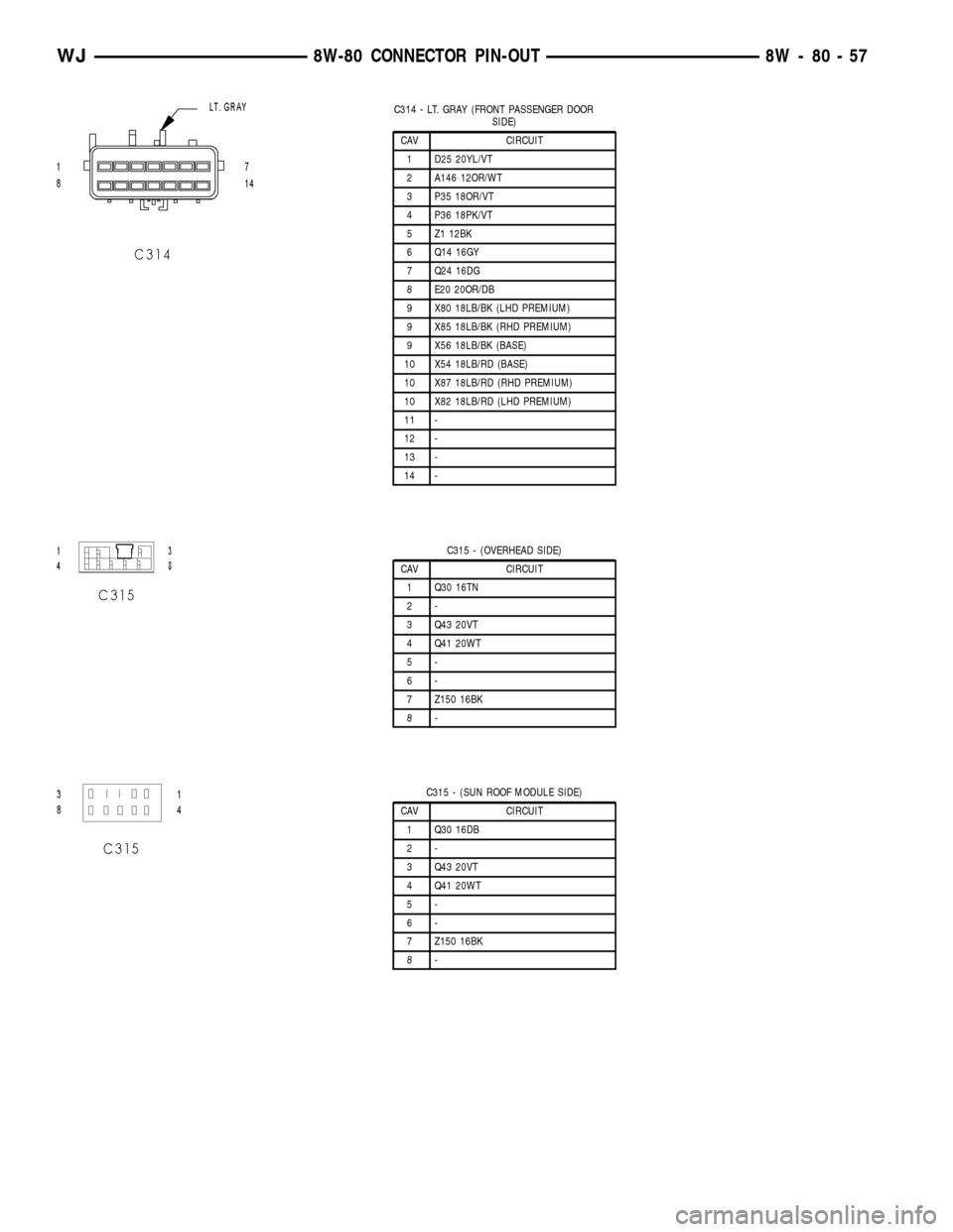
C314 - LT. GRAY (FRONT PASSENGER DOOR
SIDE)
CAV CIRCUIT
1 D25 20YL/VT
2 A146 12OR/WT
3 P35 18OR/VT
4 P36 18PK/VT
5 Z1 12BK
6 Q14 16GY
7 Q24 16DG
8 E20 20OR/DB
9 X80 18LB/BK (LHD PREMIUM)
9 X85 18LB/BK (RHD PREMIUM)
9 X56 18LB/BK (BASE)
10 X54 18LB/RD (BASE)
10 X87 18LB/RD (RHD PREMIUM)
10 X82 18LB/RD (LHD PREMIUM)
11 -
12 -
13 -
14 -
C315 - (OVERHEAD SIDE)
CAV CIRCUIT
1 Q30 16TN
2-
3 Q43 20VT
4 Q41 20WT
5-
6-
7 Z150 16BK
8-
C315 - (SUN ROOF MODULE SIDE)
CAV CIRCUIT
1 Q30 16DB
2-
3 Q43 20VT
4 Q41 20WT
5-
6-
7 Z150 16BK
8-
WJ8W-80 CONNECTOR PIN-OUT 8W - 80 - 57
Page 1154 of 2199
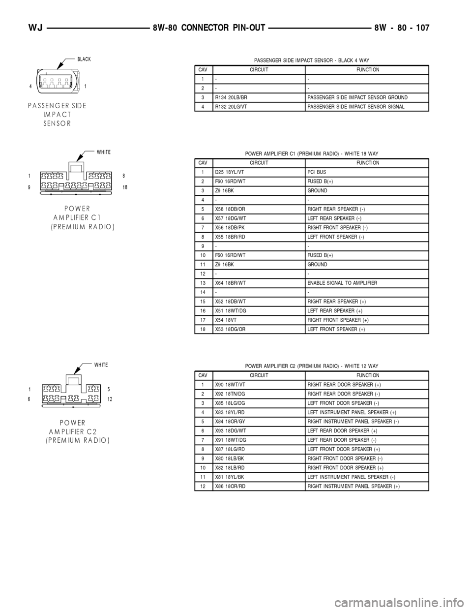
PASSENGER SIDE IMPACT SENSOR - BLACK 4 WAY
CAV CIRCUIT FUNCTION
1- -
2- -
3 R134 20LB/BR PASSENGER SIDE IMPACT SENSOR GROUND
4 R132 20LG/VT PASSENGER SIDE IMPACT SENSOR SIGNAL
POWER AMPLIFIER C1 (PREMIUM RADIO) - WHITE 18 WAY
CAV CIRCUIT FUNCTION
1 D25 18YL/VT PCI BUS
2 F60 16RD/WT FUSED B(+)
3 Z9 16BK GROUND
4- -
5 X58 18DB/OR RIGHT REAR SPEAKER (-)
6 X57 18DG/WT LEFT REAR SPEAKER (-)
7 X56 18DB/PK RIGHT FRONT SPEAKER (-)
8 X55 18BR/RD LEFT FRONT SPEAKER (-)
9- -
10 F60 16RD/WT FUSED B(+)
11 Z9 16BK GROUND
12 - -
13 X64 18BR/WT ENABLE SIGNAL TO AMPLIFIER
14 - -
15 X52 18DB/WT RIGHT REAR SPEAKER (+)
16 X51 18WT/DG LEFT REAR SPEAKER (+)
17 X54 18VT RIGHT FRONT SPEAKER (+)
18 X53 18DG/OR LEFT FRONT SPEAKER (+)
POWER AMPLIFIER C2 (PREMIUM RADIO) - WHITE 12 WAY
CAV CIRCUIT FUNCTION
1 X90 18WT/VT RIGHT REAR DOOR SPEAKER (+)
2 X92 18TN/DG RIGHT REAR DOOR SPEAKER (-)
3 X85 18LG/DG LEFT FRONT DOOR SPEAKER (-)
4 X83 18YL/RD LEFT INSTRUMENT PANEL SPEAKER (+)
5 X84 18OR/GY RIGHT INSTRUMENT PANEL SPEAKER (-)
6 X93 18DG/WT LEFT REAR DOOR SPEAKER (+)
7 X91 18WT/DG LEFT REAR DOOR SPEAKER (-)
8 X87 18LG/RD LEFT FRONT DOOR SPEAKER (+)
9 X80 18LB/BK RIGHT FRONT DOOR SPEAKER (-)
10 X82 18LB/RD RIGHT FRONT DOOR SPEAKER (+)
11 X81 18YL/BK LEFT INSTRUMENT PANEL SPEAKER (-)
12 X86 18OR/RD RIGHT INSTRUMENT PANEL SPEAKER (+)
WJ8W-80 CONNECTOR PIN-OUT 8W - 80 - 107
Page 1165 of 2199
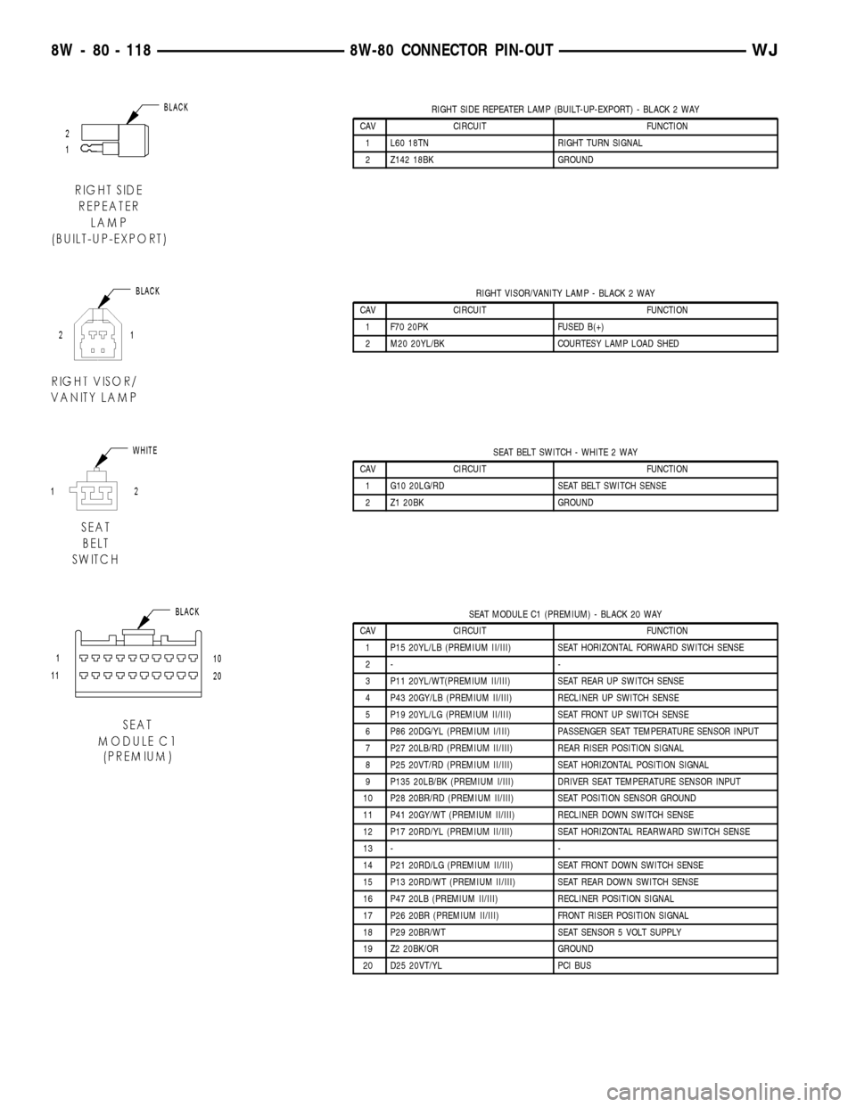
RIGHT SIDE REPEATER LAMP (BUILT-UP-EXPORT) - BLACK 2 WAY
CAV CIRCUIT FUNCTION
1 L60 18TN RIGHT TURN SIGNAL
2 Z142 18BK GROUND
RIGHT VISOR/VANITY LAMP - BLACK 2 WAY
CAV CIRCUIT FUNCTION
1 F70 20PK FUSED B(+)
2 M20 20YL/BK COURTESY LAMP LOAD SHED
SEAT BELT SWITCH - WHITE 2 WAY
CAV CIRCUIT FUNCTION
1 G10 20LG/RD SEAT BELT SWITCH SENSE
2 Z1 20BK GROUND
SEAT MODULE C1 (PREMIUM) - BLACK 20 WAY
CAV CIRCUIT FUNCTION
1 P15 20YL/LB (PREMIUM II/III) SEAT HORIZONTAL FORWARD SWITCH SENSE
2- -
3 P11 20YL/WT(PREMIUM II/III) SEAT REAR UP SWITCH SENSE
4 P43 20GY/LB (PREMIUM II/III) RECLINER UP SWITCH SENSE
5 P19 20YL/LG (PREMIUM II/III) SEAT FRONT UP SWITCH SENSE
6 P86 20DG/YL (PREMIUM I/III) PASSENGER SEAT TEMPERATURE SENSOR INPUT
7 P27 20LB/RD (PREMIUM II/III) REAR RISER POSITION SIGNAL
8 P25 20VT/RD (PREMIUM II/III) SEAT HORIZONTAL POSITION SIGNAL
9 P135 20LB/BK (PREMIUM I/III) DRIVER SEAT TEMPERATURE SENSOR INPUT
10 P28 20BR/RD (PREMIUM II/III) SEAT POSITION SENSOR GROUND
11 P41 20GY/WT (PREMIUM II/III) RECLINER DOWN SWITCH SENSE
12 P17 20RD/YL (PREMIUM II/III) SEAT HORIZONTAL REARWARD SWITCH SENSE
13 - -
14 P21 20RD/LG (PREMIUM II/III) SEAT FRONT DOWN SWITCH SENSE
15 P13 20RD/WT (PREMIUM II/III) SEAT REAR DOWN SWITCH SENSE
16 P47 20LB (PREMIUM II/III) RECLINER POSITION SIGNAL
17 P26 20BR (PREMIUM II/III) FRONT RISER POSITION SIGNAL
18 P29 20BR/WT SEAT SENSOR 5 VOLT SUPPLY
19 Z2 20BK/OR GROUND
20 D25 20VT/YL PCI BUS
8W - 80 - 118 8W-80 CONNECTOR PIN-OUTWJ
Page 1177 of 2199
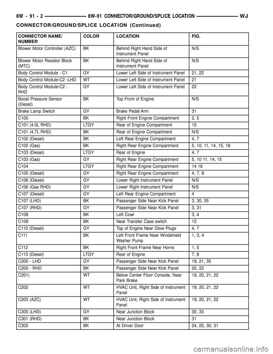
CONNECTOR NAME/
NUMBERCOLOR LOCATION FIG.
Blower Motor Controller (AZC) BK Behind Right Hand Side of
Instrument PanelN/S
Blower Motor Resistor Block
(MTC)BK Behind Right Hand Side of
Instrument PanelN/S
Body Control Module - C1 GY Lower Left Side of Instrument Panel 21, 22
Body Control Module-C2 -LHD WT Lower Left Side of Instrument Panel 21
Body Control Module-C2 -
RHDGY Lower Left Side of Instrument Panel 22
Boost Pressure Sensor
(Diesel)BK Top Front of Engine N/S
Brake Lamp Switch GY Brake Pedal Arm 31
C100 BK Right Front Engine Compartment 2, 5
C101 (4.0L RHD) LTGY Rear of Engine Compartment 15
C101 (4.7L RHD) BK Rear of Engine Compartment N/S
C102 (Diesel) BK Left Rear Engine Compartment 4, 7
C102 (Gas) BK Right Rear Engine Compartment 5, 10, 11, 14, 15, 18
C103 (Diesel) LTGY Rear of Engine 4, 7
C103 (Gas) GY Right Rear Engine Compartment 5, 10 11, 14, 15
C104 LTGY Right Rear Engine Compartment 14 18
C105 (Diesel) GY Right Rear Engine Compartment 4, 7, 8
C106 (Diesel) GY Lower Right Instrument Panel N/S
C106 (Gas RHD) GY Lower Right Instrument Panel N/S
C107 (Diesel) GY Left Rear Engine Compartment 4
C107 (LHD) BK Passenger Side Near Kick Panel 3, 30, 35
C107 (RHD) GY Passenger Side Near Kick Panel 3, 31
C108 BK Left Cowl 3, 4
C109 BK Near Transfer Case switch 12
C110 (Diesel) GY Top of Engine Near Glow Plugs 4, 7
C111 BK Left Front Frame Near Windshield
Washer Pump1, 3, 4
C112 BK Right Front Frame Near Horns 1, 5
C113 (Diesel) LTGY Rear of Engine 7, 8
C200 - LHD GY Passenger Side Near Kick Panel 19, 21, 35
C200 - RHD BK Passenger Side Near Kick Panel 20, 22
C201) WT Below Center Floor Console, Near
Park Brake19, 20, 21, 22
C202 WT HVAC Unit, Right Side of Instrument
Panel19, 20, 21, 22
C203 (AZC) WT HVAC Unit, Right Side of Instrument
Panel19, 20, 21, 22
C300 (LHD) GY Near Junction Block 30, 33
C301 (RHD) BK Near Junction Block 31
C302 BK At Driver Door 24, 25, 30, 31
8W - 91 - 2 8W-91 CONNECTOR/GROUND/SPLICE LOCATIONWJ
CONNECTOR/GROUND/SPLICE LOCATION (Continued)
Page 1178 of 2199
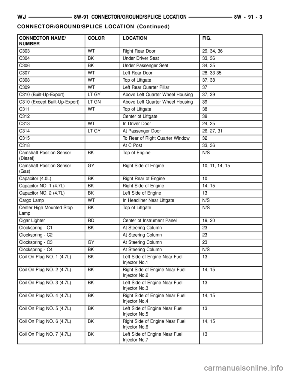
CONNECTOR NAME/
NUMBERCOLOR LOCATION FIG.
C303 WT Right Rear Door 29, 34, 36
C304 BK Under Driver Seat 33, 36
C306 BK Under Passenger Seat 34, 35
C307 WT Left Rear Door 28, 33 35
C308 WT Top of Liftgate 37, 38
C309 WT Left Rear Quarter Pillar 37
C310 (Built-Up-Export) LT GY Above Left Quarter Wheel Housing 37, 39
C310 (Except Built-Up-Export) LT GN Above Left Quarter Wheel Housing 39
C311 WT Top of Liftgate 38
C312 Center of Liftgate 38
C313 WT In Driver Door 24, 25
C314 LT GY At Passenger Door 26, 27, 31
C315 To Rear of Right Quarter Window 32
C318 At C Post 33, 36
Camshaft Position Sensor
(Diesel)BK Top of Engine N/S
Camshaft Position Sensor
(Gas)GY Right Side of Engine 10, 11, 14, 15
Capacitor (4.0L) BK Right Rear of Engine 10
Capacitor NO. 1 (4.7L) BK Right Side of Engine 14, 15
Capacitor NO. 2 (4.7L) BK Left Side of Engine 13
Cargo Lamp WT In Headliner Near Liftgate N/S
Center High Mounted Stop
LampBK Top of Liftgate N/S
Cigar Lighter RD Center of Instrument Panel 19, 20
Clockspring - C1 BK At Steering Column 23
Clockspring - C2 At Steering Column 23
Clockspring - C3 GY At Steering Column 23
Clockspring - C4 BK At Steering Column N/S
Coil On Plug NO. 1 (4.7L) BK Left Side of Engine Near Fuel
Injector No.113
Coil On Plug NO. 2 (4.7L) BK Right Side of Engine Near Fuel
Injector No.214, 15
Coil On Plug NO. 3 (4.7L) BK Left Side of Engine Near Fuel
Injector No.313
Coil On Plug NO. 4 (4.7L) BK Right Side of Engine Near Fuel
Injector No.414, 15
Coil On Plug NO. 5 (4.7L) BK Left Side of Engine Near Fuel
Injector No.513
Coil On Plug NO. 6 (4.7L) BK Right Side of Engine Near Fuel
Injector No.614, 15
Coil On Plug NO. 7 (4.7L) BK Left Side of Engine Near Fuel
Injector No.713
WJ8W-91 CONNECTOR/GROUND/SPLICE LOCATION 8W - 91 - 3
CONNECTOR/GROUND/SPLICE LOCATION (Continued)
Page 1183 of 2199
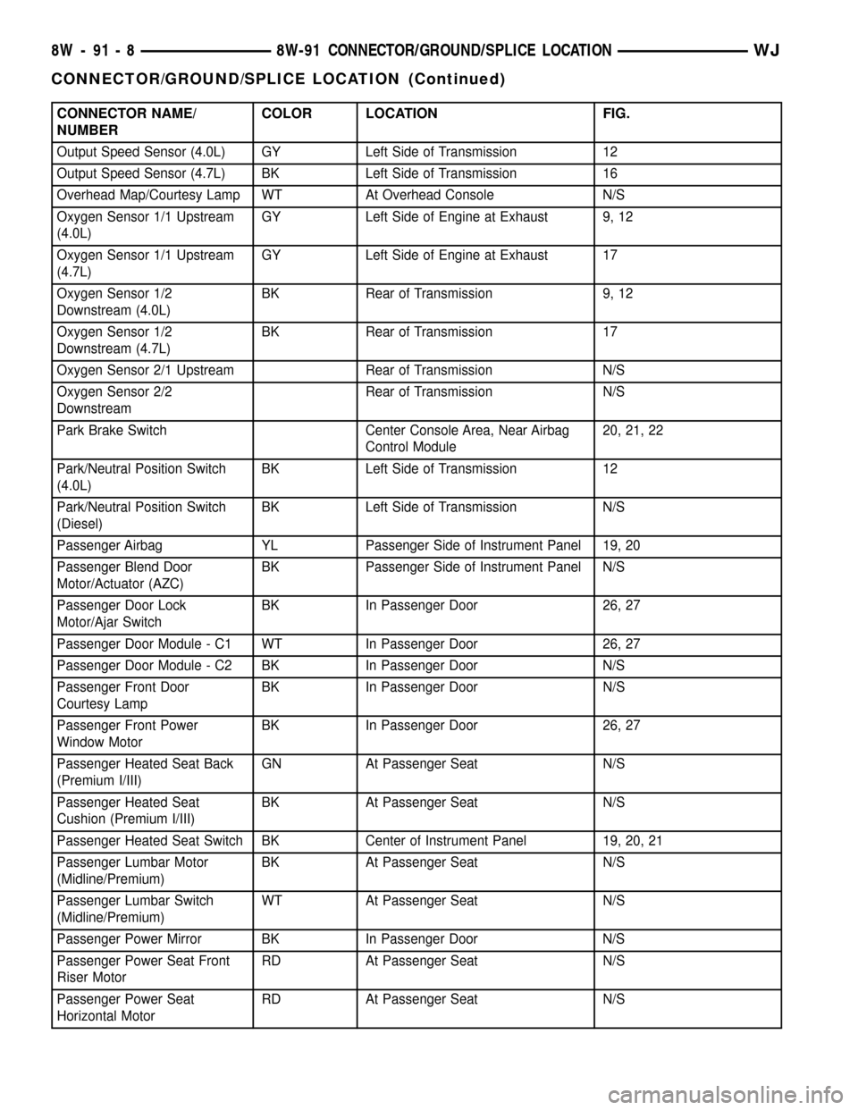
CONNECTOR NAME/
NUMBERCOLOR LOCATION FIG.
Output Speed Sensor (4.0L) GY Left Side of Transmission 12
Output Speed Sensor (4.7L) BK Left Side of Transmission 16
Overhead Map/Courtesy Lamp WT At Overhead Console N/S
Oxygen Sensor 1/1 Upstream
(4.0L)GY Left Side of Engine at Exhaust 9, 12
Oxygen Sensor 1/1 Upstream
(4.7L)GY Left Side of Engine at Exhaust 17
Oxygen Sensor 1/2
Downstream (4.0L)BK Rear of Transmission 9, 12
Oxygen Sensor 1/2
Downstream (4.7L)BK Rear of Transmission 17
Oxygen Sensor 2/1 Upstream Rear of Transmission N/S
Oxygen Sensor 2/2
DownstreamRear of Transmission N/S
Park Brake Switch Center Console Area, Near Airbag
Control Module20, 21, 22
Park/Neutral Position Switch
(4.0L)BK Left Side of Transmission 12
Park/Neutral Position Switch
(Diesel)BK Left Side of Transmission N/S
Passenger Airbag YL Passenger Side of Instrument Panel 19, 20
Passenger Blend Door
Motor/Actuator (AZC)BK Passenger Side of Instrument Panel N/S
Passenger Door Lock
Motor/Ajar SwitchBK In Passenger Door 26, 27
Passenger Door Module - C1 WT In Passenger Door 26, 27
Passenger Door Module - C2 BK In Passenger Door N/S
Passenger Front Door
Courtesy LampBK In Passenger Door N/S
Passenger Front Power
Window MotorBK In Passenger Door 26, 27
Passenger Heated Seat Back
(Premium I/III)GN At Passenger Seat N/S
Passenger Heated Seat
Cushion (Premium I/III)BK At Passenger Seat N/S
Passenger Heated Seat Switch BK Center of Instrument Panel 19, 20, 21
Passenger Lumbar Motor
(Midline/Premium)BK At Passenger Seat N/S
Passenger Lumbar Switch
(Midline/Premium)WT At Passenger Seat N/S
Passenger Power Mirror BK In Passenger Door N/S
Passenger Power Seat Front
Riser MotorRD At Passenger Seat N/S
Passenger Power Seat
Horizontal MotorRD At Passenger Seat N/S
8W - 91 - 8 8W-91 CONNECTOR/GROUND/SPLICE LOCATIONWJ
CONNECTOR/GROUND/SPLICE LOCATION (Continued)
Page 1184 of 2199
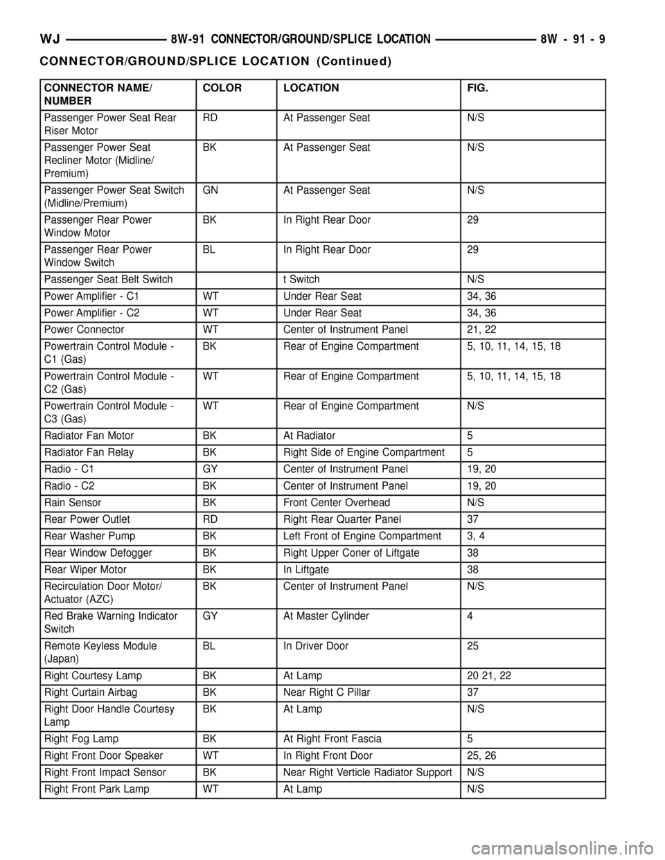
CONNECTOR NAME/
NUMBERCOLOR LOCATION FIG.
Passenger Power Seat Rear
Riser MotorRD At Passenger Seat N/S
Passenger Power Seat
Recliner Motor (Midline/
Premium)BK At Passenger Seat N/S
Passenger Power Seat Switch
(Midline/Premium)GN At Passenger Seat N/S
Passenger Rear Power
Window MotorBK In Right Rear Door 29
Passenger Rear Power
Window SwitchBL In Right Rear Door 29
Passenger Seat Belt Switch t Switch N/S
Power Amplifier - C1 WT Under Rear Seat 34, 36
Power Amplifier - C2 WT Under Rear Seat 34, 36
Power Connector WT Center of Instrument Panel 21, 22
Powertrain Control Module -
C1 (Gas)BK Rear of Engine Compartment 5, 10, 11, 14, 15, 18
Powertrain Control Module -
C2 (Gas)WT Rear of Engine Compartment 5, 10, 11, 14, 15, 18
Powertrain Control Module -
C3 (Gas)WT Rear of Engine Compartment N/S
Radiator Fan Motor BK At Radiator 5
Radiator Fan Relay BK Right Side of Engine Compartment 5
Radio - C1 GY Center of Instrument Panel 19, 20
Radio - C2 BK Center of Instrument Panel 19, 20
Rain Sensor BK Front Center Overhead N/S
Rear Power Outlet RD Right Rear Quarter Panel 37
Rear Washer Pump BK Left Front of Engine Compartment 3, 4
Rear Window Defogger BK Right Upper Coner of Liftgate 38
Rear Wiper Motor BK In Liftgate 38
Recirculation Door Motor/
Actuator (AZC)BK Center of Instrument Panel N/S
Red Brake Warning Indicator
SwitchGY At Master Cylinder 4
Remote Keyless Module
(Japan)BL In Driver Door 25
Right Courtesy Lamp BK At Lamp 20 21, 22
Right Curtain Airbag BK Near Right C Pillar 37
Right Door Handle Courtesy
LampBK At Lamp N/S
Right Fog Lamp BK At Right Front Fascia 5
Right Front Door Speaker WT In Right Front Door 25, 26
Right Front Impact Sensor BK Near Right Verticle Radiator Support N/S
Right Front Park Lamp WT At Lamp N/S
WJ8W-91 CONNECTOR/GROUND/SPLICE LOCATION 8W - 91 - 9
CONNECTOR/GROUND/SPLICE LOCATION (Continued)
Page 1230 of 2199
JUNCTION BLOCK
DESCRIPTION
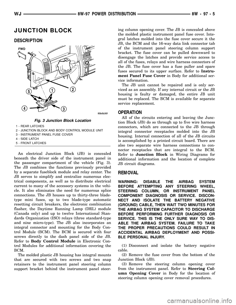
An electrical Junction Block (JB) is concealed
beneath the driver side of the instrument panel in
the passenger compartment of the vehicle (Fig. 3).
The JB combines the functions previously provided
by a separate fuseblock module and relay center. The
JB serves to simplify and centralize numerous elec-
trical components, as well as to distribute electrical
current to many of the accessory systems in the vehi-
cle. It also eliminates the need for numerous splice
connections. The JB houses up to thirty-three blade-
type mini fuses, up to two blade-type automatic
resetting circuit breakers, the electronic combination
flasher, the Daytime Running Lamp (DRL) module
(Canada only) and up to twelve International Stan-
dards Organization (ISO) relays (three standard-type
and nine micro-type). The JB also incorporates an
integral connector and mounting for the Body Con-
trol Module (BCM). The BCM is secured with four
screws directly to the dash panel side of the JB.
Refer toBody Control Modulein Electronic Con-
trol Modules for additional information covering the
BCM.
The molded plastic JB housing has integral mounts
that are secured with two screws and two snap
retainers to the instrument panel steering column
support bracket behind the instrument panel steer-ing column opening cover. The JB is concealed above
the molded plastic instrument panel fuse cover. Inte-
gral latches molded into the fuse cover secure it the
JB, the BCM and the 16-way data link connector tab
of the instrument panel steering column support
bracket. The fuse cover can be pulled downward to
disengage the latches and provide service access to
all of the fuses, relays and wire harness connectors of
the JB. The fuse cover has a fuse puller and spare
fuses secured to its upper surface. Refer toInstru-
ment Panel Fuse Coverin Body for additional ser-
vice information.
The JB unit cannot be repaired and is only ser-
viced as an assembly. If any internal circuit or the JB
housing is faulty or damaged, the entire JB unit
must be replaced. The BCM is available for separate
service replacement.
OPERATION
All of the circuits entering and leaving the Junc-
tion Block (JB) do so through up to five wire harness
connectors, which are connected to the JB through
integral connector receptacles molded into the JB
housing. Internal connection of all of the JB circuits
is accomplished by a printed circuit board. There are
also two separate wire harness connections to con-
nector receptacles that are integral to the BCM.
Refer toJunction Blockin Wiring Diagrams for
additional information and the location of complete
JB circuit diagrams.
REMOVAL
WARNING: DISABLE THE AIRBAG SYSTEM
BEFORE ATTEMPTING ANY STEERING WHEEL,
STEERING COLUMN, OR INSTRUMENT PANEL
COMPONENT DIAGNOSIS OR SERVICE. DISCON-
NECT AND ISOLATE THE BATTERY NEGATIVE
(GROUND) CABLE, THEN WAIT TWO MINUTES FOR
THE AIRBAG SYSTEM CAPACITOR TO DISCHARGE
BEFORE PERFORMING FURTHER DIAGNOSIS OR
SERVICE. THIS IS THE ONLY SURE WAY TO DIS-
ABLE THE AIRBAG SYSTEM. FAILURE TO TAKE
THE PROPER PRECAUTIONS COULD RESULT IN
ACCIDENTAL AIRBAG DEPLOYMENT AND POSSI-
BLE PERSONAL INJURY.
(1) Disconnect and isolate the battery negative
cable.
(2) Remove the fuse cover from the bottom of the
Junction Block (JB).
(3) Remove the steering column opening cover
from the instrument panel. Refer toSteering Col-
umn Opening Coverin Body for the location of
steering column opening cover removal procedures.
Fig. 3 Junction Block Location
1 - REAR LATCHES
2 - JUNCTION BLOCK AND BODY CONTROL MODULE UNIT
3 - INSTRUMENT PANEL FUSE COVER
4 - SIDE LATCH
5 - FRONT LATCHES
WJ8W-97 POWER DISTRIBUTION 8W - 97 - 5
Page 1238 of 2199
outlet receptacle and a good ground. There should be
continuity. If OK, go to Step 4. If not OK, go to Step
5.
(4) Check for battery voltage at the insulated con-
tact located at the back of the power outlet recepta-
cle. If not OK, go to Step 5.
(5) Disconnect and isolate the battery negative
cable. Remove the instrument panel center lower
bezel. Check for continuity between the ground cir-
cuit cavity of the power outlet wire harness connector
and a good ground. There should be continuity. If
OK, go to Step 6. If not OK, repair the open ground
circuit to ground as required.
(6) Connect the battery negative cable. Check for
battery voltage at the fused B(+) circuit cavity of the
power outlet wire harness connector. If OK, replace
the faulty power outlet receptacle. If not OK, repair
the open fused B(+) circuit to the junction block fuse
as required.
REMOVAL
(1) Disconnect and isolate the battery negative
cable.
(2) Remove the center lower bezel from the instru-
ment panel. Refer toInstrument Panel Center
Lower Bezelin Body for the procedure.
(3) Pull the cigar lighter knob and element or the
protective cap out of the cigar lighter receptacle base,
or open the power outlet door in the instrument
panel center lower bezel.
(4) Look inside the cigar lighter or power outlet
receptacle base and note the position of the rectangu-
lar retaining bosses of the mount that secures the
receptacle base to the instrument panel center lower
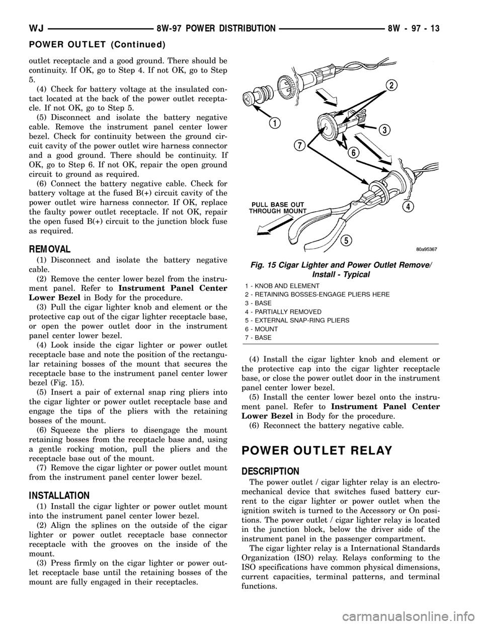
bezel (Fig. 15).
(5) Insert a pair of external snap ring pliers into
the cigar lighter or power outlet receptacle base and
engage the tips of the pliers with the retaining
bosses of the mount.
(6) Squeeze the pliers to disengage the mount
retaining bosses from the receptacle base and, using
a gentle rocking motion, pull the pliers and the
receptacle base out of the mount.
(7) Remove the cigar lighter or power outlet mount
from the instrument panel center lower bezel.
INSTALLATION
(1) Install the cigar lighter or power outlet mount
into the instrument panel center lower bezel.
(2) Align the splines on the outside of the cigar
lighter or power outlet receptacle base connector
receptacle with the grooves on the inside of the
mount.
(3) Press firmly on the cigar lighter or power out-
let receptacle base until the retaining bosses of the
mount are fully engaged in their receptacles.(4) Install the cigar lighter knob and element or
the protective cap into the cigar lighter receptacle
base, or close the power outlet door in the instrument
panel center lower bezel.
(5) Install the center lower bezel onto the instru-
ment panel. Refer toInstrument Panel Center
Lower Bezelin Body for the procedure.
(6) Reconnect the battery negative cable.
POWER OUTLET RELAY
DESCRIPTION
The power outlet / cigar lighter relay is an electro-
mechanical device that switches fused battery cur-
rent to the cigar lighter or power outlet when the
ignition switch is turned to the Accessory or On posi-
tions. The power outlet / cigar lighter relay is located
in the junction block, below the driver side of the
instrument panel in the passenger compartment.
The cigar lighter relay is a International Standards
Organization (ISO) relay. Relays conforming to the
ISO specifications have common physical dimensions,
current capacities, terminal patterns, and terminal
functions.
Fig. 15 Cigar Lighter and Power Outlet Remove/
Install - Typical
1 - KNOB AND ELEMENT
2 - RETAINING BOSSES-ENGAGE PLIERS HERE
3 - BASE
4 - PARTIALLY REMOVED
5 - EXTERNAL SNAP-RING PLIERS
6 - MOUNT
7 - BASE
WJ8W-97 POWER DISTRIBUTION 8W - 97 - 13
POWER OUTLET (Continued)
Page 1239 of 2199
The cigar lighter relay cannot be repaired or
adjusted and, if faulty or damaged, it must be
replaced.
OPERATION
The ISO relay consists of an electromagnetic coil, a
resistor or diode, and three (two fixed and one mov-
able) electrical contacts. The movable (common feed)
relay contact is held against one of the fixed contacts
(normally closed) by spring pressure. When the elec-
tromagnetic coil is energized, it draws the movable
contact away from the normally closed fixed contact,
and holds it against the other (normally open) fixed
contact.
When the electromagnetic coil is de-energized,
spring pressure returns the movable contact to the
normally closed position. The resistor or diode is con-
nected in parallel with the electromagnetic coil in the
relay, and helps to dissipate voltage spikes that are
produced when the coil is de-energized.
DIAGNOSIS AND TESTING - POWER OUTLET
RELAY
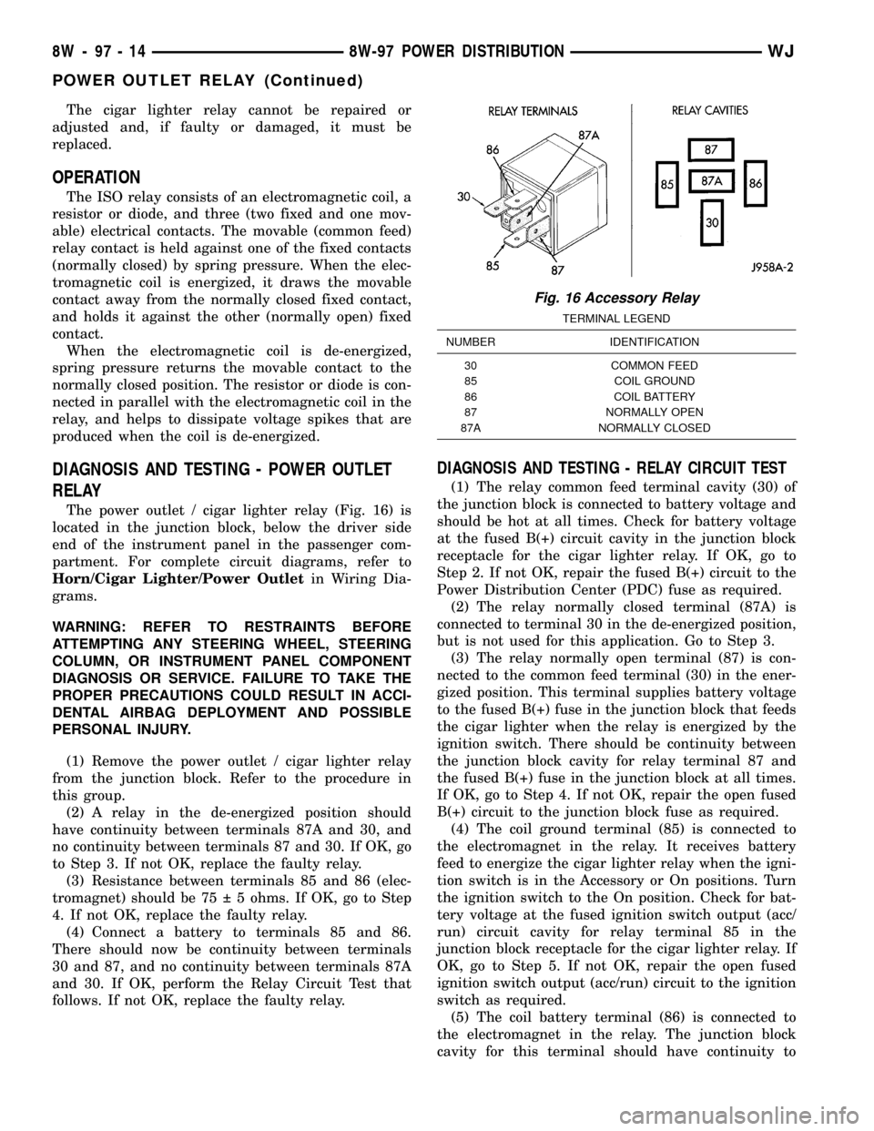
The power outlet / cigar lighter relay (Fig. 16) is
located in the junction block, below the driver side
end of the instrument panel in the passenger com-
partment. For complete circuit diagrams, refer to
Horn/Cigar Lighter/Power Outletin Wiring Dia-
grams.
WARNING: REFER TO RESTRAINTS BEFORE
ATTEMPTING ANY STEERING WHEEL, STEERING
COLUMN, OR INSTRUMENT PANEL COMPONENT
DIAGNOSIS OR SERVICE. FAILURE TO TAKE THE
PROPER PRECAUTIONS COULD RESULT IN ACCI-
DENTAL AIRBAG DEPLOYMENT AND POSSIBLE
PERSONAL INJURY.
(1) Remove the power outlet / cigar lighter relay
from the junction block. Refer to the procedure in
this group.
(2) A relay in the de-energized position should
have continuity between terminals 87A and 30, and
no continuity between terminals 87 and 30. If OK, go
to Step 3. If not OK, replace the faulty relay.
(3) Resistance between terminals 85 and 86 (elec-
tromagnet) should be 75 5 ohms. If OK, go to Step
4. If not OK, replace the faulty relay.
(4) Connect a battery to terminals 85 and 86.
There should now be continuity between terminals
30 and 87, and no continuity between terminals 87A
and 30. If OK, perform the Relay Circuit Test that
follows. If not OK, replace the faulty relay.
DIAGNOSIS AND TESTING - RELAY CIRCUIT TEST
(1) The relay common feed terminal cavity (30) of
the junction block is connected to battery voltage and
should be hot at all times. Check for battery voltage
at the fused B(+) circuit cavity in the junction block
receptacle for the cigar lighter relay. If OK, go to
Step 2. If not OK, repair the fused B(+) circuit to the
Power Distribution Center (PDC) fuse as required.
(2) The relay normally closed terminal (87A) is
connected to terminal 30 in the de-energized position,
but is not used for this application. Go to Step 3.
(3) The relay normally open terminal (87) is con-
nected to the common feed terminal (30) in the ener-
gized position. This terminal supplies battery voltage
to the fused B(+) fuse in the junction block that feeds
the cigar lighter when the relay is energized by the
ignition switch. There should be continuity between
the junction block cavity for relay terminal 87 and
the fused B(+) fuse in the junction block at all times.
If OK, go to Step 4. If not OK, repair the open fused
B(+) circuit to the junction block fuse as required.
(4) The coil ground terminal (85) is connected to
the electromagnet in the relay. It receives battery
feed to energize the cigar lighter relay when the igni-
tion switch is in the Accessory or On positions. Turn
the ignition switch to the On position. Check for bat-
tery voltage at the fused ignition switch output (acc/
run) circuit cavity for relay terminal 85 in the
junction block receptacle for the cigar lighter relay. If
OK, go to Step 5. If not OK, repair the open fused
ignition switch output (acc/run) circuit to the ignition
switch as required.
(5) The coil battery terminal (86) is connected to
the electromagnet in the relay. The junction block
cavity for this terminal should have continuity to
Fig. 16 Accessory Relay
TERMINAL LEGEND
NUMBER IDENTIFICATION
30 COMMON FEED
85 COIL GROUND
86 COIL BATTERY
87 NORMALLY OPEN
87A NORMALLY CLOSED
8W - 97 - 14 8W-97 POWER DISTRIBUTIONWJ
POWER OUTLET RELAY (Continued)